Bindicator Bin-Flo L Series User manual

Bin-Flo®Aerators
Installation & Operation Manual
IOM
LBF980006 Rev. D
O
Or
rd
de
er
r
f
fr
ro
om
m:
:
C
C
A
A
B
Br
ri
ig
gg
gs
s
C
Co
om
mp
pa
an
ny
y
622 Mary Street; Suite 101; Warminster, PA 18974
Phone: 267-673-8117 -
Fax: 267-673-8118
- www.cabriggs.com

Bin-Flo®Aerators
Installation & Operation Manual
CONTENTS
I. HANDLING & STORAGE .......................................................................................................................... 1
Inspection and Handling
Disposal and Recycling
Storage
II. GENERAL SAFETY................................................................................................................................... 2
Authorized Personnel
Use
Misuse
III. PRODUCT DESCRIPTION ....................................................................................................................... 3
IV. INSTALLATION ......................................................................................................................................... 6
Guidelines
Mounting Considerations
V. DIMENSIONAL DRAWINGS..................................................................................................................... 7
SAFETY SYMBOLS
WARNING:
IDENTIFIES CONDITIONS OR PROCEDURES, WHICH IF NOT FOLLOWED,
COULD RESULT IN SERIOUS INJURY. RISK OF ELECTRICAL SHOCK.
CAUTION:
IDENTIFIES CONDITIONS OR PROCEDURES, WHICH IF NOT FOLLOWED,
COULD RESULT IN SERIOUS DAMAGE OR FAILURE OF THE EQUIPMENT.


1
www.bindicator.com
I. HANDLING AND STORAGE
SAVE THESE INSTRUCTIONS
INSPECTION AND HANDLING
Do not dispose of the carton or packing materials.
Each package should be inspected upon receipt for damage that may have occurred due to mishandling
during shipping. If the unit is received damaged, notify the carrier or the factory for instructions. Failure to do
so may void your warranty. If you have any problems or questions, consult Bindicator®Customer Support at
1-800-778-9242.
DISPOSAL AND RECYCLING
This product can be recycled by specialized companies and must not be disposed of in a municipal collection
site. If you do not have the means to dispose of properly, please contact Bindicator®for return and disposal
instructions or options.
STORAGE
If the product is not scheduled for immediate installation following delivery, the following steps should be
observed:
1. Following inspection, repackage the unit into its original packaging.
2. Select a clean dry site, free of vibration, shock and impact hazards.
3. If storage will be extended longer than 30 days, the unit must be stored at temperatures between -40
and 70° C in non-condensing atmosphere with humidity less than 85%.
Bin-Flo®Aerators

2
www.bindicator.com
II. GENERAL SAFETY
AUTHORIZED PERSONNEL
All instructions described in the document must be performed by authorized and qualied service personnel
only. Before installing the unit, please read these instructions and familiarize yourself with the requirements and
functions of the device. The required personal protective equipment must always be worn when servicing this
device.
USE
The device is solely intended for use as described in this manual. Reliable operation is ensured only if the
instrument is used according to the specications described in this document. For safety and warranty
reasons, use of accessory equipment not recommended by the manufacturer or modication of this device is
explicitly forbidden. All servicing of this equipment must be performed by qualied service personnel only. This
device should be mounted in locations where it will not be subject to tampering by unauthorized personnel.
MISUSE
Improper use or installation of this device may cause the following:
• Personal injury or harm
• Application specic hazards such as vessel overll
• Damage to the device or system
If any questions or problems arise during installation of this equipment, please contact the Bindicator®
Customer Support at 800-778-9242.
3
www.bindicator.com
III. PRODUCT DESCRIPTION
FUNCTION
The Bin-Flo® aerator is a simple and efcient means of introducing low pressure air into any dry nely ground
material. The air is equally distributed in controlled quantities to give the material the ability to ow by gravity
from bins, hoppers or chutes. Bin-Flo aerators incorporate non-clogging diffusers, an integral orice and
construction features which assure long, maintenance-free life.
FEATURES
Simple Installation
• Can be installed from inside or outside the bin
Integral Orice
• Controls air consumption at any recommended pressure
Non-clogging Diffuser
• Provides equal distribution of air and will not clog when air is on even with the nest materials
SPECIFICATIONS
Tank Nipple and Locknut “L” Series - 1/8“ (3 mm) brass
“LL” Series - 1/4” (6 mm) plated steel
Spacer Washers Nickel plated steel
Diffuser Up to 180° F (82° C) cotton (canvas)
Up to 600° F (316° C) fiberglass
Diffuser Frame Galvanized steel 16 mesh or stainless steel mesh type 316
Body Zinc plated steel or stainless steel
Shipping Weight “L” Series - .75 lb ea
“LL” Series - 1.75 lb ea
“LL” Series has a diffusion area approximately 21/2times that of “L” Series. When installed in larger bins, it will reduce the
number of aerators and the amount of piping required.

4
www.bindicator.com
IV. INSTALLATION
L SERIES - INTERNAL
Drill 7/16” hole through the bin wall or mounting surface at the center of each Bin-Flo aerator location. Insert the
tank nipple (short tapered thread end) in the aerator and place the unit inside the bin, inserting the tank nipple
through the drilled hole in the bin wall.
Place the gasket on the nipple next to the outside of the bin wall together with sufcient space wahsers and
lock securely in place with the locknut.
Install piping to the Bin-Flo aerators and complete connection to the air supply.
LL SERIES - INTERNAL
Drill 9/16”hole through the bin wall at the center of each Bin-Flo aerator location and proceed as above.
AIR SUPPLY PIPING
Piping of adequate size to carry the required volume of low pressure air must be provided to assure reliable
operation of the Bin-Flo aerator. As a general guide the following minimum pipe sizes should be used for
the manifolds to which the aerators are attached. In all cases the number of pipe ttings should be held to a
minimum.
L SERIES LL SERIES
Pipe Size No. of Bin-Flo
Aerators
Pipe Size No. of Bin-Flo
Aerators
3/4” (19 mm) 1 - 5 1” (25.4 mm) 1 - 5
1” (25.4 mm) 6 - 9 11/4” (32 mm) 6 - 8
11/4” (32 mm) 10 - 12 11/2” (38 mm) 9 - 11
5
www.bindicator.com
AIR SUPPLY
A continuous air supply must be maintained at all times to insure a proper operation of the Bin-Flo aerators. Lack
of air supply will cause the material to build up on the aerators and result in damage to the aerators.
The best and usually most economical air supply is from a positive displacement low pressure blower. For
test applications or applications involving less than 30 CFM, compressors may be used in conjunction with a
pressure reducing regulator and lter or moisture trap on the low pressure side.
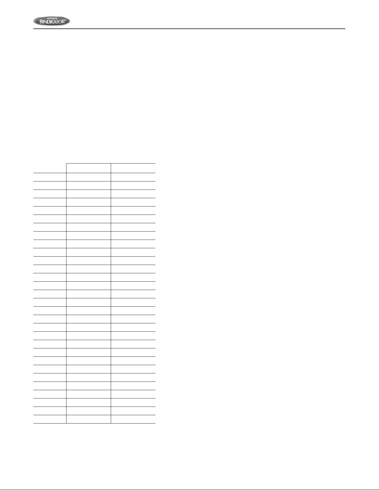
The following table shows the volume of air one Bin-Flo aerator (uncovered) will use at various operating
pressures. Check the pressure near the most distant Bin-Flo aerators with the bin empty.
Air Pressure
PSI
Air Consumption per Bin-Flo Aerator -
in Cubic Feet per Minute
L Series LL Series
1/22.7 6.0
1 4.2 7.5
11/25.0 9.1
2 5.7 10.5
21/26.1 11.7
*3 6.5 12.7
31/26.9 13.8
4 7.1 14.7
41/27.4 15.6
5 7.6 16.4
51/28.0 17.2
6 8.2 18.3
61/28.4 19.2
7 8.7 20.2
71/28.9 21.1
8 9.1 22.0
81/29.3 23.0
9 9.6 23.8
91/29.8 24.7
10 10.0 25.6
101/210.2 26.5
11 10.4 27.4
111/210.7 28.4
12 10.9 29.2
121/211.1 30.1
13 11.3 30.9
131/211.6 31.9
14 11.8 32.9
141/212.0 33.8
15 12.2 35.1
*3 PSI is recommended and used on most applications.
15 PSI is the maximum pressure.
6
www.bindicator.com
HOW MANY BIN-FLO AERATORS PER ROW?
To determine the number of Bin-Flo aerators required for each row, measure the length of the sloping side of
the hopper on which the aerators are to be installed. Refer to the table below, select the model to be used
(L Series or LL Series) and the spacing of the units. Read down the column until the approximate length of slope
is reached. The number of aerators required is shown at the right.
Example: The 6’11” slope will require 6 model L aerators mounted on 15” centers.
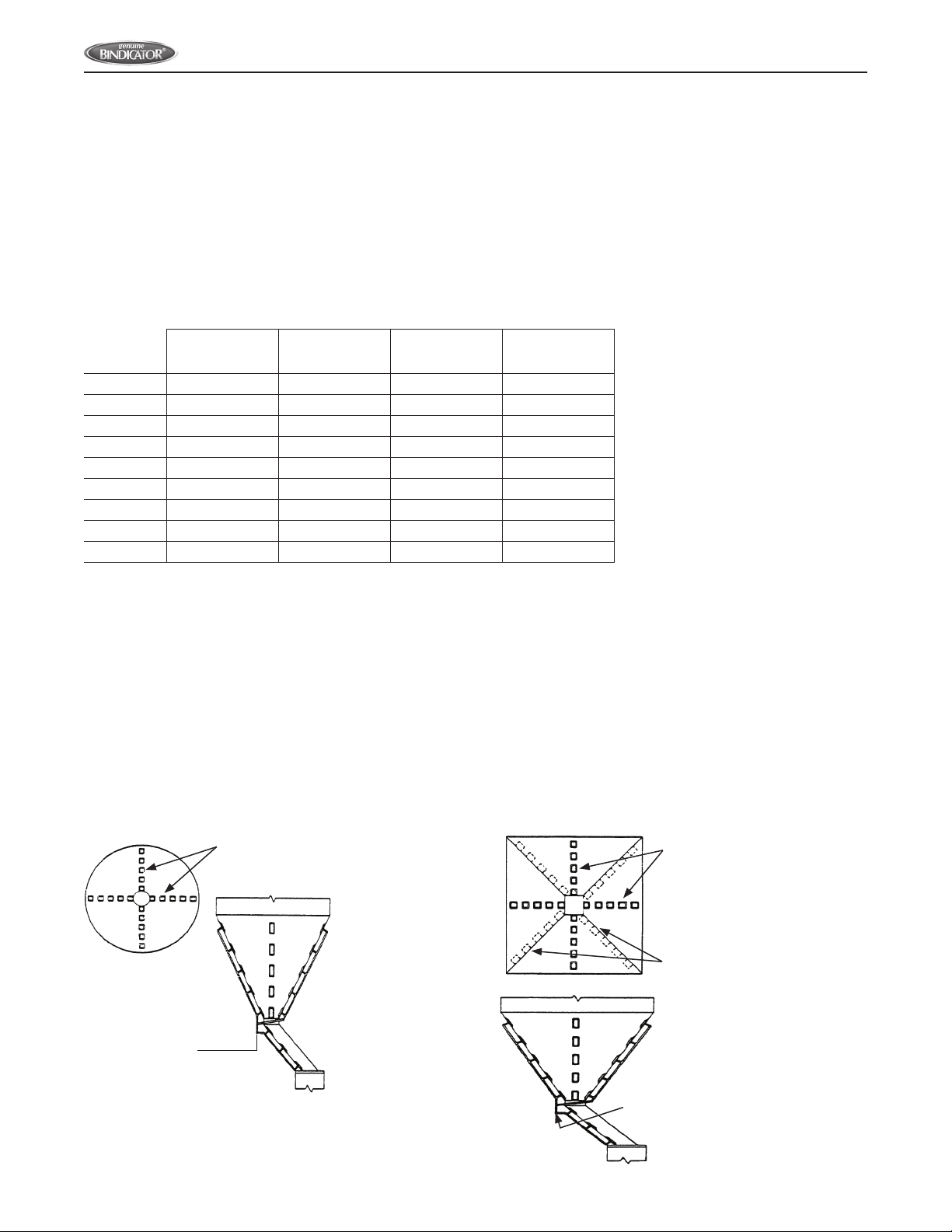
CONICAL HOPPER
In a conical hopper four rows of Bin-Flo aerators,
located as shown, are normally required. The L
Series should be used in small cones as the smaller
aerator adapts better to the curved surface. To
prevent clogging of material in discharge pipe or
chute, install one row of aerators on the under side
of the slope as shown.
PYRAMIDAL HOPPER
In a pyramidal hopper, four rows of Bin-Flo aerators
centered on the sloping sides usually assures full
and uniform ow. For minimum retention of material
in the corners, an alternate location in the valleys
is suggested. To prevent clogging of material in
discharge pipe or chute, install one row of aerators
on the underside of the slope as shown.
Number of
Aeration
Pads per
Row
L Series Mounted On LL Series Mounted On
12” Centers 15” Centers 20” Centers 24” Centers
2 1’ 8” (50.8 cm) 1’ 11” (50.8 cm) 2’ 8” (81 cm) 3’ 0” (91 cm)
3 2’ 8” (81 cm) 3’ 2” (81 cm) 4’ 4” (132 cm) 5’ 0” (152 cm)
4 3’ 8” (112 cm) 4’ 5” (112 cm) 6’ 0” (183 cm) 7’ 0” (213 cm)
5 4’ 8” (142 cm) 5’ 8” (142 cm) 7’ 8” (234 cm) 9’ 0” (274 cm)
6 5’ 8” (173 cm) 6’ 11” (173 cm) 9’ 4” (284 cm) 11’ 0” (335 cm)
7 6’ 8” (203 cm) 8’ 2” (203 cm) 11’ 0” (335 cm) 13’ 0” (396 cm)
8 7’ 8” (234 cm) 9’ 5” (234 cm) 12’ 8” (386 cm) 15’ 0” (457 cm)
9 8’ 8” (264 cm) 10’ 8” (264 cm) 14’ 4” (437 cm) 17’ 0” (518 cm)
10 9’ 8” (295 cm) 11’ 11” (295 cm) 16’ 0” (488 cm) 19’ 0” (579 cm)
Bin-Flo Aerators
Air Supply
Bin-Flo Aerators
Alternate Locations
Air Supply

7
www.bindicator.com
V-BOTTOM BIN
This arrangement may be used in bins emptied by screw conveyor, belt conveyor or other means where the
discharge opening runs the entire length of the bin. It provides full and uniform ow to the discharge opening
without bridging over the outlet. Number of rows of Bin-Flo aerators required and spacing will depend upon the
size of the bin as well as the material being handled.
Bin-Flo Aerators
Air Supply
INSTALLATION IN
FLAT BOTTOM
Bin-Flo Aerators
Pipe manifold of
adequate size
V. DIMENSIONAL DRAWINGS
L Series LL Series
A 33
/
4” (95.25 mm) 6” (152.39 mm)
B 71
/
2” (190.5 mm) 12” (304.8 mm)
C7
/
16” (11.09 mm) 11
/
16” (17.46 mm)
D
1
/
8” Pipe x 2” Long
OD = 0.405
(10.29mm x 50.8mm)
1
/
4” Pipe x 2” Long
OD = 0.540
(13.72mm x 50.8mm)
A
B
C
D
C
Air Baffle
Bin Wall
Lock
Nut
Nipple
Shown with 1/2” hole in wall
of bin or bottom of chute for
internal mounting
Non-clogging air
diffuser fabric:
Cotton or Fiberglass Air Pressure
Equalizing
Chamber
Stainless or zinc
plated steel body
Galvanized steel or 316 SS
mesh framework above and
below diffuser fabric.

150 Venture Boulevard
Spartanburg, SC 29306
Tel: (800) 778-9242
Fax: (864) 574-8063
sales@bindicator.com
www.bindicator.com
2012 All rights reserved.
All data subject to change without notice.
LBF980006 Rev. D
This manual suits for next models
1
Table of contents
Popular Lawn And Garden Equipment manuals by other brands

GÜDE
GÜDE GV 4000 B Translation of the original instructions

Echo
Echo HC-150 HEDGE CLIPPER - PARTS CATALOG SERIAL NUMBER S76112001001 -... parts catalog

Gronomics
Gronomics Rustic Elevated Garden Bed Assembly instructions

Innovation Industries
Innovation Industries Hummer Hearth use instructions

Smithco
Smithco Fairway Ultra 10 12-501-B Parts & Service operators

Toro
Toro Lynx SmartHub Installation and user guide


