Binks QS-5012-CE User manual

Page 1 © ITW Inc 2007
EN
EN P 1 - 12 D
D
P 24 - 34
F
F
P 13 - 23 NL
NL
P 35 - 45
IT
IT
P 46 - 56
AIR MOTOR DRIVES and AGITATORS for
PRESSURE FEED TANKS
IMPORTANT: Read and follow all instructions and SAFETY PRECAUTIONS
before using this equipment. Retain for future reference.
SBBI-E-19-095 iss1

Page 2
© ITW Inc 2007
AIR MOTOR DRIVES and AGITATORS for
PRESSURE FEED TANKS
IMPORTANT: Read and follow all instructions and SAFETY PRECAUTIONS
before using this equipment. Retain for future reference.
DESCRIPTION
This manual covers the following models;
QS-5012-CE Air motor drive with 15:1 gear reduction.
Includes air adjusting for speed control with hose and
fittings for tank regulator connection.
QMS-431-CE, 433-CE and 434-CE Agitator for use with
QS-5012-CE Gear reduction drive on 2, 10 and 15 gall
tanks models. Alternatively can be used without a drive
motor for manual operation.
QMS-430-CE direct drive air motor and Agitator. Used on
83S-211-CE SS Pressure Feed tanks. Includes air adjusting
for speed control with hose and fittings for tank regulator
connection.
PT-427/418-CE direct drive air motor for use on 83C and
83Z-211-CE pressure feed tanks.
PT-419/428-CE agitator shaft and impellor for use with PT-
427-CE/418-CE.
All models are suitable for use with flammable coating
materials and for use in a Zone 1 classified hazardous
area.
These Agitators are CE marked in accordance with the
ATEX Directive 94/9/EC for hazardous area use and
Machinery Safety Directive 98/37/EC.
These Agitators are designed for use with Pressure
Tanks. These are pressure containers to supply liquid
material at a constant preset pressure up to a maximum
of 7.0 bar. Read all the information contained in this
bulletin and the pressure feed tank bulletin before
attempting installation.
SBBI-E-19-095
Part Number ATEX classification Type approval certificate Number
QS-5012-CE II 2 G c T4 TRL06ATEX21105X
QMS-431-CE, 433-CE & 434-CE II 1/2 G c T4 TRL06ATEX21107X
QMS-430-CE II 1/2 G c T4 TRL06ATEX21106X
PT-427-CE/418-CE & PT-419-CE/428-CE II 1/2 G c T4 TRL06ATEX21109X
All Models Ambient temperature range +1ºC to 40ºC (34 to 104ºF)
All models are certified for use in Hazardous areas, Zone 1 for areas around the tank and Zone 0 for
inside the tank. Temperature class T4 (135˚C).

Page 3 © ITW Inc 2007
The following hazards may occur during the normal use of this equipment. Please read the following chart.
HAZARD CAUSE SAFEGUARDS
EXPLOSION STATIC ELECTRICITY
Use of this equipment in a
potentially explosive
atmosphere.
Vapours from flammable liquids
can catch fire or explode from
static electricity discharges.
1. If installing this equipment in a potentially explosive atmosphere,
check the ATEX equipment category and temperature ratings meet
the requirements for the zoned area.
2. Check electrical continuity of the air supply to earth - should be no
greater than 106 Ω.
3. Electrically bond all metallic equipment to earth. Should be no greater
than 1 Ω.
INHALING TOXIC
SUBSTANCES
Certain materials may be harmful
if inhaled, or there is contact with
the skin.
1. Follow the requirements of the Material Safety Data Sheet
supplier by the coating manufacturer.
2. Adequate exhaust must be provided to keep the air free of
accumulations of toxic materials.
3. Use a mask or respirator wherever there is a risk of inhaling
sprayed materials. The mask must be suitable for the material
being sprayed.
SPECIAL
CONDITIONS FOR
SAFE USE
REQUIRED BY
ATEX
CERTIFICATION
Over pressurization of equipment
can cause equipment failure or
injury.
Use lubricating medium resistant
to carburisation.
Improper operation or
maintenance may create a
hazard.
1. Do not exceed the stated maximum working pressures and motor
speed as specified on page 3.
2. Only a suitably approved static dissipating or conductive air supply
hoses shall be attached to the equipment and terminated to the air
supply.
3. Air supplies (compressors etc) shall be sited in a non-hazardous area
with a filter on the air intake system to prevent the ingress of dust or
similar foreign material into the parts where compression takes place.
4. Use lubricating medium resistant to carburisation and has an auto
ignition temperature of more than 185ºC for T4 equipment.
5. User shall verify the presence of gearbox lubricant (QS-5012-CE
only) in accordance with the instructions on P5, before operating the
air motor.
6. User shall ensure all metallic parts of the equipment are suitably
bonded to earth. Should be no greater than 1 Ω.
GENERAL SAFETY Air stream from product may
contain solid or liquid material
that can result in eye injury.
Sound level from air motors may
exceed 80 dba.
Improper operation or
maintenance may create a
hazard.
1. Wear eye protection when using this equipment.
2. Wearing of ear protection is recommended.
3. Operators should be given adequate training in the safe use and
maintenance of this equipment. Refer to Pressure Systems Safety
Regulations 2000 Approved Code of Practice.
Important information that tells how to
prevent damage to equipment, or how to
avoid a situation that may cause minor injury.
Important safety information - A hazard that
may cause serious injury or loss of life.
NOTE
Information that you should pay special
attention to.
SAFETY PRECAUTIONS
This manual contains information that is important for you to know and understand. This information relates to USER SAFETY and
PREVENTING EQUIPMENT PROBLEMS. To help you recognize this information, we use the following symbols. Please pay particular
attention to these sections

Page 4
© ITW Inc 2007
INSTALLATION
Air Supply
Air supplies (compressors etc) shall be sited
in a non-hazardous area with a filter on the
air intake system to prevent the ingress of
dust or similar foreign material into the parts
where compression takes place.
Pressure Relief Procedure
Before attempting any installation of agitators
onto pressure feed tanks, the tanks must be
relieved of pressure as high pressure can
cause a serious injury. Pressure is
maintained in a pressure tank after the
system has been shut down. Before
attempting removal of fill plug or cover,
pressure must be relieved using the following
steps:
1. Turn off the main air supply to the tank.
2. Close air inlet valve located on tank air
manifold.
3. Bleed off air in the tank by turning the air
relief valve thumb screw counter-clockwise.
Wait until all the air has escaped through the
valve before removing the pressure tank
cover or fill plug installation.
4. Leave the air relief valve open until you
have reinstalled the cover or fill plug.
Air Motor Lubrication (all models)
An automatic air line filter/lubricator should
be installed in the air supply line no more
than 0.5m from the air motor. The filter
should be 5 micron. Install the lubricator level
with or above the motor so the oil mist will
blow directly into or down into the motor (see
Fig. 1).
Fill the oil reservoir with SAE 10W motor oil.
Adjust lubricator to feed 1 drop of oil for
every 1400 litres (50 cfm) of air or 1 drop per
minute for continuous running.
QS-5012-CE Gear reduction drive—
INSTALLATION onto Pressure Feed
Tank with Agitator (Fig. 5)
1. These instructions are for fitting of the
QS-5012-CE drive unit to an installed
QMS-431-CE, 433-CE or 434-CE
agitator. (See QMS-431-CE, 433-CE and
434-CE installation section).
2. Make sure lower clamp bolt (61) is
loosened, then take the drive unit and
slide the support (60) over the bearing
assembly, making sure the square drive
on the shaft engages the drive socket of
the gearbox. Rotate the unit if necessary
to align the shaft and socket.
3. Tighten the lower clamp bolt (61) and
check the upper bolt.
4. Remove main air supply inlet valve from
the tank regulator and install service tee
(67) in open port.
5. Connect tank air supply inlet valve to
open end port of service tee (67). Install
nipple (64) in open port of service tee.
6. If not already connected, install elbow
(63) in air motor inlet port and upper
nipple (64) in open elbow port. Connect
air adjusting valve (65) to upper nipple.
Connect hose assembly (66) between
lower nipple (64) and air adjusting valve.
QMS-431-CE, 433-CE and 434-CE
Agitator—INSTALLATION into
Pressure Feed Tank
1. Follow the pressure relief procedure at
the start of the INSTALLATION section.
2. Unscrew the centre blanking plug from
the tank cover.
3. Remove the paddle(s) from the shaft by
loosening the paddle clamp screw.
4. Make sure the O ring (26) is located
correctly in the housing (25). Screw
housing into the centre hole in the tank
lid. Fully tighten with a spanner (1.875
AF).
5. Refit the paddles in the position as
SPECIFICATION
Agitator cross reference chart
Agitator Code Type of Agitation Used with; Max rpm Max recommended
rpm
Max pressure
QS-5012-CE Indirect Geared Drive Agitator & motor QMS-431-CE, 433-CE
& 434-CE
200 60 7 bar
QMS-431-CE Agitator only (less drive) for 8 ltr tanks 83S-213-CE 200 60 7 bar
QMS-433-CE Agitator only (less drive) for 40 ltr tanks 83S-1013-CE
83G-1013-CE
200 60 7 bar
QMS-434-CE Agitator only (less drive) 83S-1513-CE
200 60 7 bar
QMS-430-CE Direct Drive 83S-211-CE 3000 1000 7 bar
PT-427-CE/418-CE Direct drive 83Z-211-CE 3000 1000 7 bar
Materials of Construction
All Air Motors
Motor bodies Cast Iron
End Plates Aluminium
Rotors Cast Iron rotor, Stainless Steel Shaft (except PT-419-CE Carbon Steel)
QS-5012-CE Gearbox Housing Cast Iron
QMS-431-CE, 433-
CE, 434-CE
Bearing housing & Drive Shaft Stainless Steel with Oilite bearings
Paddles Conductive Nylon
PT-419-CE/428-CE Direct drive 83C-211-CE 3000 1000 7 bar
Shaft Seals Turcon (modified PTFE)
Fig 1

Page 5 © ITW Inc 2007
shown in fig 2. The curved edge of the
paddle should be at the bottom. Upper
paddle on 60L QMS-434-CE only.
QS-430-CE Direct Drive Agitator—
INSTALLATION into Pressure Feed
Tank (Fig. 9)
1. Follow the pressure relief procedure at
the start of the INSTALLATION section.
2. Unscrew the centre blanking plug from
the tank cover. Clean the sealing surface
around the port.
3. Loosen the propeller screw (56A) and
remove the propeller.
4. Make sure the O ring (65) is fully seated
in the groove in the adaptor (34). Insert
the agitator through the port and screw in
until fully tightened.
5. If required, loosen the screw (34A) in the
adaptor to rotate the motor body to align
the hose connection to the required
position. Re-tighten the screw (34A)
6. Replace the propeller (56) onto the shaft
(54). Make sure the screw is aligned with
the flat on the shaft and tighten screw
(56A).
7. Remove main air supply inlet valve from
the tank regulator and install service tee
(23) in open port.
8. Connect tank air supply inlet valve to
open end port of service tee (23). Install
nipple (20) in open port of service tee.
9. If not already connected, install elbow
(19) in air motor inlet port and upper
nipple (20) in open elbow port. Connect
air adjusting valve (21) to upper nipple.
Connect hose assembly (22) between
lower nipple (20 and air adjusting valve.
PT-427-CE/418-CE & PT-419-CE/428-
CE Agitator—INSTALLATION into
Pressure Feed Tank (Fig.8)
1. The PT-428/PT-419 direct drive Agitator
is designed for the 83C-211-CE and
83Z-211-CE tanks only. This Agitator
would be supplied with the tank and is
not supplied as a retro-fit or upgrade, but
only as a replacement.
2. Follow the pressure relief procedure at
the start of the INSTALLATION section.
3. If replacing the original unit, disconnect
the air supply hose from the air motor,
remove the propeller (56), then un-screw
the large nut (53). The unit will now
withdraw from the tank lid.
4. Re-fit the new unit in the reverse order.
Make sure the nut (53) is fully tightened
with a spanner (1—5/8” AF). Re-fit hoses
air hose.
OPERATION
Failure to operate and maintain these
agitators correctly could result in
premature motor failure and void
warranty.
Before operating any of these agitators
lubricate the air motor by adding 4 of 5
drops of SAE 10 weight oil into the air
fitting
QS-5012-CE Operation (Fig. 5)
1. Before operating the air motor, check the
oil level of the gearbox.
2. Remove the oil fill plug (88) and check
the oil level (see Fig. 3 below).
3. If oil level is low, add 140 weight SAE
motor oil. Replace the plug and tighten to
27Nm (20 ftlbs).
4. Before turning on the air supply, screw in
the air adjusting valve (65) fully. Turn on
the air supply and slowly open up the air
adjusting valve until the desired speed is
reached. A good starting point is 1 rev
per second (60 rpm).
5. Run the agitator continuously whist using
the tank.
6. When the tank is empty, the motor speed
will rise. Stop the motor to avoid un-
necessary high speed running.
QMS-430-CE and PT-428-CE Direct
drive models (Fig. 9)
1. Before turning on the air supply, screw in
the air adjusting valve (21) fully. Turn on
the air supply and slowly open up the air
adjusting valve until the desired speed is
reached. Use a minimum of 4 bar air
pressure. Do not exceed the maximum
of 7 bar.
2. Run the agitator continuously whist using
the tank.
3. When the tank is empty, the motor speed
will rise. Stop the motor to avoid un-
necessary high speed running.
PREVENTATIVE
MAINTENANCE
Pressure Relief Procedure
Before attempting any MAINTENANCE of
agitators onto pressure feed tanks, the tanks
must be relieve of pressure as high pressure
can cause a serious injury. Pressure is
maintained in a pressure tank after the
system has been shut down. Before
attempting removal of fill plug or cover,
pressure must be relieved using the
following steps:
1. Turn off the main air supply to the tank.
2. Close air inlet valve located on tank air
manifold.
3. Bleed off air in the tank by turning the air
relief valve thumb screw counter-
clockwise. Wait until all the air has
escaped through the valve before
removing the pressure tank cover or fill
plug installation.
4. Leave the air relief valve open until you
have reinstalled the cover or fill plug.
QS-5012-CE Preventative
Maintenance
1. Every 2 days, check the oil level as
described in the operation section. Top
up as necessary.
2. After the first 250 hours of operation,
remove the gearbox (see replacement of
parts section) and drain the gearbox oil.
Replace the oil as per the operation
section. Note—do this when the gearbox
is warm as the oil will drain easier.
3. After 6 months or 2500 operating hours,
replace the oil as in 2 above.
All Air Motors
1. Lubricate Air Motor as per Installation
section on page 3.
2. Check exhaust muffler filter every 500
hours. Clean or replace as necessary.
3. If the Air motor starts to run slowly or is
sluggish, flushing the motor with solvent
may restore its performance due to
excessive contamination from oil,
moisture and foreign particles. Use only
Gast #AH255B Flushing Solvent or
equivalent for this.
4. This cleaning operation should only be
carried out in a well ventilated area.
5. Wear eye protection.
6. Do not use combustible solvents for
flushing.
7. Disconnect the airline and muffler. Add
Fig 3
Fig 2

Page 6
© ITW Inc 2007
about 100ml (4 fluid oz) of solvent into
the air intake port of the motor. Rotate
the motor by hand in both directions for a
few minutes.
8. Re-connect the airline and cover the
exhaust port with a cloth. Apply low
pressure 0.7bar (10psi) and re-start the
motor. Run until no more traces of
solvent can be seen.
9. The motor should be running smoothly. If
not, then a re-build may be required (see
QS-4016 Replacement of Parts).
REPLACEMENT OF
PARTS
QS-5012-CE Replacement of parts
(see Figs 5 & 6)
Before attempting any MAINTENANCE of
agitators on pressure feed tanks, the tanks
must be relieve of pressure as stated
previously.
1. Turn off and disconnect the mains air
supply hose with the air adjusting valve
(65).
2. Loosen the upper clamp screw (61) and
remove the air motor and gearbox
assembly.
3. Separate the motor and gearbox by
loosening locking screw (91).
4. Remove the spacer (94) and key (95)
from the motor shaft.
5. For the Air motor refer to QS-4016 Air
motor section.
Gear box
1. Remove the oil fill plug (88) or cover
plate (84) and drain gear box lubricant.
2. Disassemble the gearbox by removing
the cover (84), withdraw the gear shaft
(86) and washer (85).
3. Withdraw the worm gear (93) .
4. Inspect the seal (90) for signs of wear,
leaks or damage. Only remove if it needs
replacing.
5. Clean the seal housing and remove any
burrs or contaminants. These could
distort the new seal during fitting.
6. Inspect the gear shaft assembly (86) for
wear grooves, burrs or contamination of
seal sealing area on the shaft diameter.
If the seal sealing area is damaged the
shaft must be replaced.
7. Inspect all other parts for signs of wear,
chipping or other damage. Replace
damaged or worn parts.
8. If the oil seal (90) is being replaced,
check the new seal carefully for damage
before installing. Use an arbour press to
press the seal in. Use a close fitting tool
to the casting bore diameter to avoid
damaging the seal. Make sure the seal
lip is towards the bottom of the bore.
Press in squarely into the bore to avoid
warping. Check that the seal is fully
seated in the bottom of the bore.
9. Reassemble gear box in the reverse
order. Use new gaskets (87 and 92).
When re-fitting the air motor, slide
spacer (94) and fit key (95) before
engaging the motor to the gearbox.
Apply thread locking compound to the
locking screws (91) and tighten to 6.8
Nm (60 lbins). Refill the gearbox with oil
(SAE 10) as per previous section.
QMS-431-CE, 433-CE and 434-CE
Agitator Replacement of parts (see
Fig. 7)
Before attempting any MAINTENANCE of
agitators on pressure feed tanks, the tanks
must be relieve of pressure as stated
previously.
1. Remove lid from pressure feed tank.
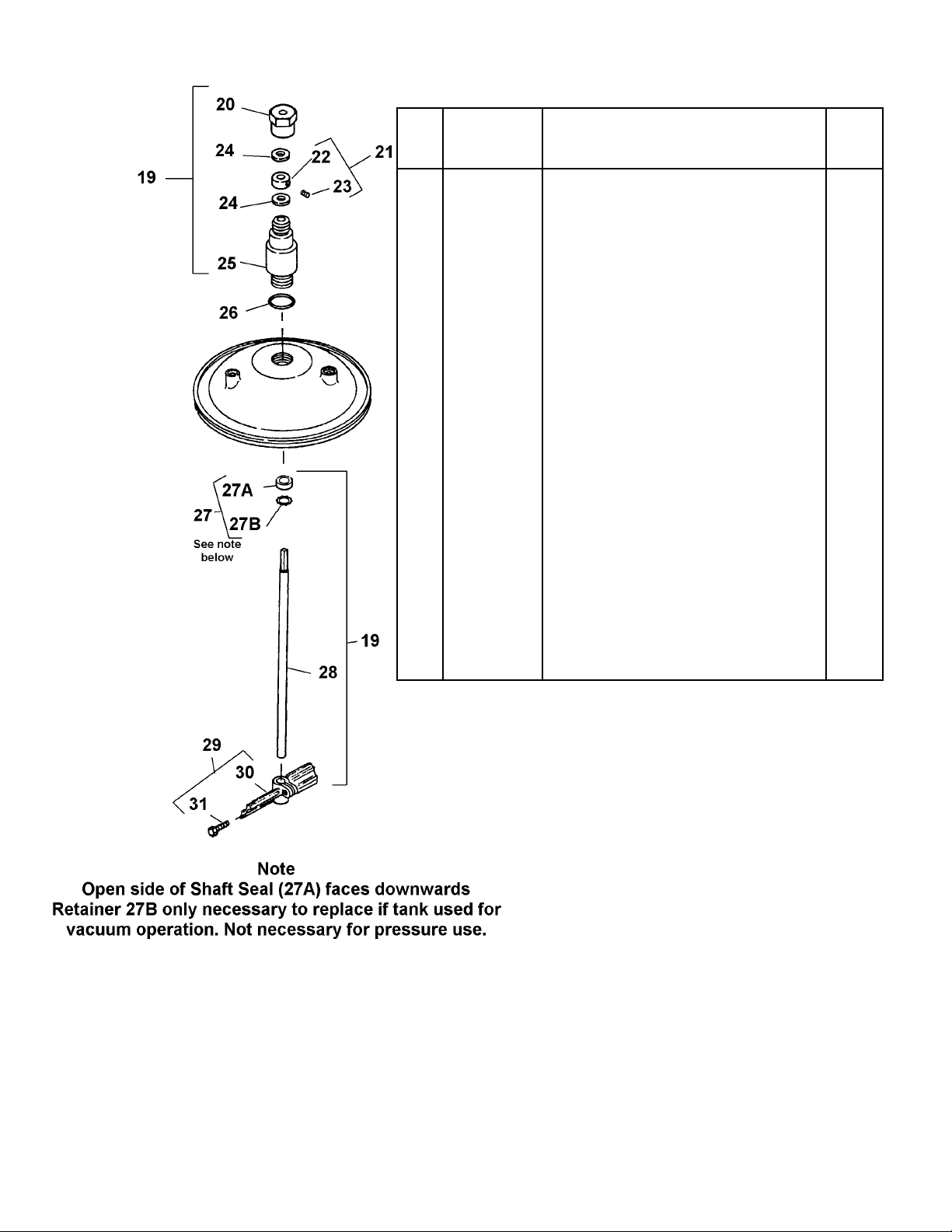
2. Remove paddles by loosening screw(s)
(31).
3. Unscrew retaining nut (20) and remove.
4. Hold the shaft (28), loosen set screw
(23) on the collar (22). The collar (22)
and washers (24) can now be removed.
5. The shaft can now be withdrawn from
the bearing housing (25). Be careful with
the shaft seal (27) as any burrs or dried
paint could damage the lip seal.
6. If the O ring (26) is to be replaced,
unscrew and remove the bearing
assembly (25).
7. Examine the Shaft seal (27A) for any
damage. If it needs replacement, prise
out the retaining clip (27B), then the seal
(27A). Take care not to damage the seat
in the bearing housing (25).
8. Check the size of the oilite bearings in
the housing (25) for wear. These are
15.6mm when new. Replace when the
size is 15.9mm (0.626”) or greater.
9. Take a new seal (27A) and apply a small
amount of water or oil to the outside to
lubricate the fitted O ring.
10. Place the seal in the housing (25) O ring
first with the grooves facing outwards.
Press the seal in making sure it is seated
fully in the housing.
11. Clean the O ring groove in the housing
(25) and make sure the seating surface
on the tank lid is clean. Place the O ring
(26) in the groove and lightly lubricate it
with water or light oil. Screw the housing
(25) into the lid and fully tighten with a
spanner.
12. Take the shaft (28) and insert the
paddle end into the top of the housing
(25) and feed through, taking care when
feeding through the Shaft seal (27A).
13. Hold the shaft (28) with the groove about
12mm from then top of the housing (25)
and slip thrust washer (24) then collar
(22) over the end. Align the set screw
(23) in the collar (22) with the groove
and tighten. Fit 2nd washer (24).
14. Screw on retainer nut (20) onto the
bearing housing (25) and tighten with a
spanner.
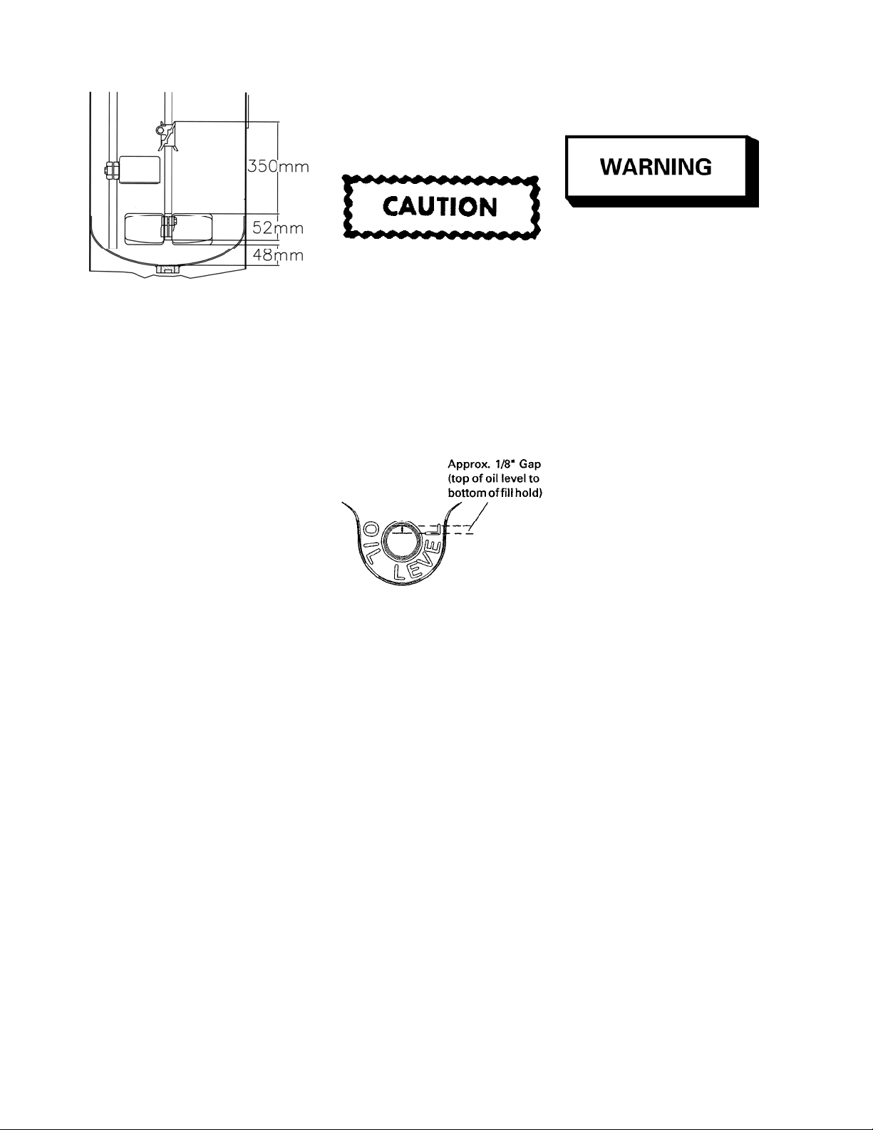
15. Slide paddle(s) (29) over the shaft and
position as shown in Fig. 2 in the
installation section.
16. Re-fit the drive motor QS-5012-CE as
per installation section.
QMS-430-CE and
PT-428-CE/PT-419-CE
Replacement of parts (Figs 8 & 9)
Before attempting any MAINTENANCE of
agitators on pressure feed tanks, the tanks
must be relieve of pressure as stated
previously.
1. Turn off air supply with the air adjusting
valve (21) and disconnect the main air
supply hose.
2. Remove Lid from pressure feed tank.
3. Remove propeller (55).
4. Loosen screws (49) and remove retainer
(32A), Shaft (54) with the propeller (55).
5. Loosen screws (34A) or (49) and Air
motor (33) or (35) can be withdrawn from
the housing (34) or (48).
6. For replacement of parts procedure for
the Air motor see section for QS-4016
below. Some of the references are
different but the procedure is the same.
7. Examine the Seal (50) for damage or
wear. Only remove if it needs replacing.
8. Take a new seal (50A) and apply a small
amount of water or oil to the outside to
lubricate the fitted O ring.
9. Place the seal in the housing (34) O ring
first with the grooves facing outwards.
Press the seal in making sure it is seated
fully in the housing.
10. Replace the Air motor and shaft
assembly in reverse order.
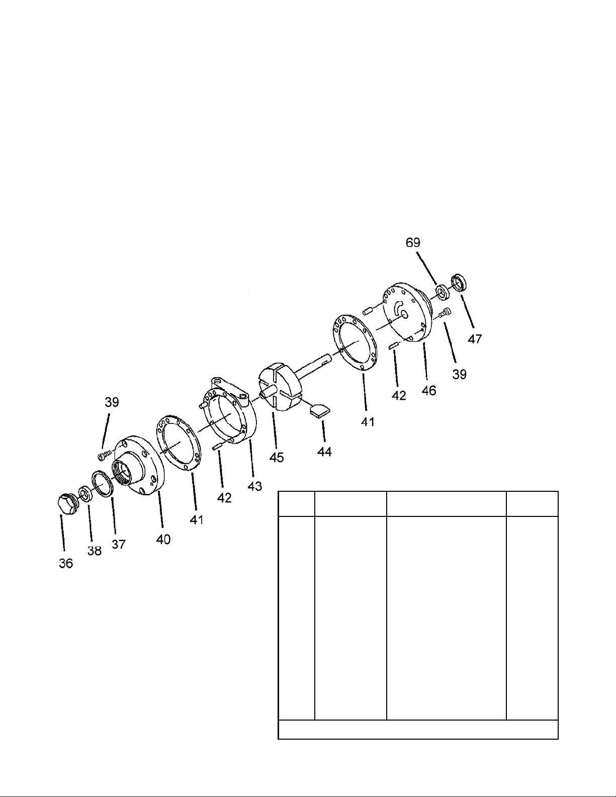
QS-4016 Air Motor Replacement of
parts (for QS-5012-CE)
1. Remove the end cap (36) or (64) for
QMS-430-CE.
2. Remove dead end plate bolts (39).
3. Remove dead end plate (40). Use a
puller, do not use screwdriver to remove
the end plate.)
4. Remove the dowel pins (42) from the
body and push back into end plate (40)
until flush or just below the machined
surface of the dead end plate. Remove
rotor (45) using an arbor press.
5. Remove vanes (44).
6. Remove shaft seal (47) and bearing (38)
or (69) from drive end plate (46) and
bearing (38) from dead end plate (40).
Do Not remove drive end plate bolts or
drive end plate (46).
7. Clean parts. Check for scoring on the

Page 7 © ITW Inc 2007
Fig 4
Ref.
No.
Replacement
Part No.
Description Individual
Parts Req.
36 QS-190 End Cap 1
•37 - End Cap Gasket 1
38 PT-58 Bearing 1
39 Purchase Locally Machine Screw 1/4”-28 x 1/2” 1
40 QS-333 Front plate 1
•41 PT-59-1-K10 End Plate Gasket Kit (kit of 10) 2
42 QS-189-1-K10 Dowel Pin (kit of 10) 4
43 QS-335 Body 1
•44 - Vane 4
45 QS-442 Rotor and Shaft Assy 1
46 QS-334 End Plate 1
47 QS-197 Bearing 1
68 QS-336 Oil Seal 1
•Included in KK-5001-1 Air Motor Repair Kit.
end plates and rotor assembly. If scoring
exists, send unit to a Gast Authorized
Service Facility.
8. Check the bearings for signs of wear.
Replace the bearings at least every 2
years.
9. Place the drive shaft of the rotor
assembly (45) through the drive end
plate (46). Press the drive bearing (69)
onto the drive shaft using a bearing
pusher.
10. Using a suitable tool, lightly tap on inner
race of the drive end bearing (69) to
snug up rotor (45) to drive end plate
(46).
11. Check the vanes (44) for wear. If the
height of the vanes are less than
17.5mm (11/16”) then re-new the vanes.
Install new vanes (44), the angle cuts on
the vane face to the center of the rotor.
12. Place the end plate gasket (41) on the
body of dead end (40). If the original is
damaged, replace with a new one
supplied in the service kit.
13. Place the dead end plate (40) on the
body.
14. Install the dead end bearing (38) and
press into place with bearing pusher tool.
15. Install the dowel pins (42).
16. Fully tighten the remaining bolts to 8.5 -
11.3 Nm (75-100 in-lbs).
17. Set end clearance to the values at the
end of this section. lightly tap on the
inner race of the dead end bearing to
free up and center the rotor in the body.
18. Apply a small amount of grease to
bearing seal (47) and install the drive
end bearing seal by pressing flush with
bearing pushing tool from Tool Kit.
19. Reattach end cap (36) or (64) with new
gasket ((37).
20. Apply a few drops of 10w oil lubricant
into ports and rotate shaft by hand for a
few rotations.
End Clearances
Total clearance
.063mm (0.0025”)
Top end clearance
.038mm (0.0015”)

Page 8
© ITW Inc 2007
Ref.
No.
Replacement
Part No.
Description Individual
Parts Req.
•82 - Filister Head Machine screw 10-
24 x 5/8” 4
83 QS-108 Pressure Relief fitting 1
84 QS-37-1 Cover Plate 1
•85 - Washer 1
86 QS-416-1 Gear & Shaft assy. 1
•87 - Gasket 1
88 Purchase
locally Pipe Plug 1/4” Galvanized 1
89 QS-36-1 Housing 1
•90 - Oil Seal 1
•91 - Cup point setscrew 5/16” x 3/8” 2
•92 - Gasket 1
93 QS-59 Worm Gear 1
•94 - Spacer 1
•95 - Key, No.5, 5/8”/x 1/8” 1
•Included in KK-5010 Gearbox Repair Kit.
Ref.
No.
Replacement
Part No.
Description Individual
Parts Req.
53 350-401 Air Strainer 1
54 - Strainer Cap 1
+ 55 - Screen 1
· + 56 - Felt 1
57 - Strainer Body 1
58 - Gearbox Assembly (see fig 6) 1
59 32243-133 Washer 1
60 QMS-35 Air Motor Support 1
61 - Cap screw 3/8” x 16 UNC x 2” 2
62 QS-4016 Air Motor 1
63 - Street Elbow 1/4”(M) 1/4”NPT(F) 1
64 H-2008 Nipple 1/4” NPS(M) 1
65 HAV-500 Air Adjusting Valve 1
66 HA-57011 Hose Assembly 1
67 - Service Tee 1/4” 1
+ Ref. No. (55) 2ea and Ref. No. (56) 4ea included in KK-5006 Strainer
Screen and Felt Kit.
•Included in KK-5001-1 Air Motor Repair Kit. See fig 4 for full list of parts
in the kit.
Fig 5
Fig 6

Page 9 © ITW Inc 2007
Fig 7 QMS-431, 433 and 434 AGITATOR PARTS LIST
Ref.
No.
Part No. Description No of
Parts
Req.
19 QMS-431-CE Agitator Assembly 8L (includes items 20 to 31) 1
QMS-433-CE Agitator Assembly 40L 1
QMS-434-CE Agitator Assembly 60L 1
20 QMS-46 Retaining Nut 1
21 QMS-447 Thrust Collar Kit (includes items 22 and 23) 1
22 — Thrust Collar 1
♦23 — Set Screws (5/16” - 18 x 3/8”) 1
24 KK-5049 Thrust Washer Kit (includes 2 Washers) 1
25 QMS-407 Bearing Assembly 1
26 SSG-8184-K2 O-Ring (kit of 2) 1
27 KK-5042 Shaft Seal Kit 2
27A — Shaft Seal 1
27B — Retainer 1
28 QMS-5 Agitator Shaft for QMS-431-CE 1
QMS-7 Agitator Shaft for QMS-433-CE 1
QMS-8 Agitator Shaft for QMS-434-CE 1
29
QMS-444-CE Agitator Paddle Kit (includes items 30 and 31) 1
QMS-434-CE 60L models has 2 2
QMS-449-CE Agitator Paddle Kit for 8L QMS-431-CE
30 — Agitator Paddle 1
♦31 — Hex Socket head Cap Screw (5/16” x 1-1/4”,
stainless Steel) 1
♦Purchase locally

Page 10
© ITW Inc 2007
Parts list for PT-427-CE, PT-418-CE,
PT-419-CE & PT-428-CE
Fig 8
Ref.
No.
Replacement Part
No.
Description Individual
Parts Req.
* 35
PT-410 83C
Air Motor Assembly 1
QMS-455 83Z
36
QS-190 83C
End Cap 1
PT-65 83Z
* 37 ——– End Cap Gasket 1
38 PT-58 Bearing 1
39 ——– Screw (1/4”-28 x 1/2”) 12
* 40 ——– Front Plate 1
* 41 PT-59-1-K10 End Plate Gasket 2
42 QS-189-1-K10 Dowel Pin (Kit of 10) 4
•43 ——– Body 1
* 44 ——– Vane 4
•
**45 ——– Rotor Assembly 1
•46 ——– End Plate 1
47 PT-56 Shaft Seal 1
48 PT-50 Air Motor Adaptor 1
49 ——– Set Screw (1/4”-20 x 1/4”) 4
50 KK-5041 Seal Assembly 1
QMG-441 83C Shaft Coupling Kit (includes
No 49) 1
QMS-453 83Z
52 SSG-8096-K5 “O” Ring (Kit of 5) 1
53 PT-70 Adaptor Nut 1
54 QMG-56 83C Shaft 1
QMS-73 83Z Shaft SS 1
55 QMS-448-CE Propeller Assy 1
56 ——– Propeller 1
56A ——– Set Screw (1/4”-20 x 3/8”
S.S) 1
57 350-401 Muffler Assembly 1
58 ——– Body 1
♦59 ——– Screen 2
♦ * 60 ——– Felt 1
61 ——– Cap 1
# 62
PT-428-CE 83C
Agitator Shaft Kit 1
PT-419-CE 83Z
66
PT-418-CE 83C
Air Motor & Adaptor 1
PT-427-CE 83Z
* Parts included in KK-5001-1 Air Motor Repair Kit
•Parts included in (35) PT-410/QMS-455 Air Motor Assembly
♦Ref. No. (59) 2 ea. & Ref. No. (60) 4 ea. Included in KK-5006 Strainer
Screen & Felt kit
** Not available separately, order (35) PT-410/QMS-455
51

Page 11 © ITW Inc 2007
Ref.
No.
Replacement
Part No.
Description Individual
Parts Req.
19 ——-- Street Elbow 1/4”(M)
1/4”NPT(F) 1
20 H-2008 Nipple 1/4” NPS(M) 2
21 HAV-500 Air Adjusting Valve 1
22 HA-57001 Hose assembly 1
23 ——- Service Tee 1/4” 1
32A KK-4991 Agitator Kit 1
33 QMS-428
Motor Assembly (incl parts
#4 to 18). Use #1, 2 & 3
from old motor.
1
34 ——- Air Motor Adaptor 1
34A ——- Set Screw (1/4”-20 x 1/4”) 1
* 37 ——– End Cap Gasket 1
38 PT-58 Bearing 1
39 ——– Screw (1/4”-28 x 1/2”) 12
40 ——– Front Plate 1
* 41 PT-59-1-K10 End Plate Gasket 2
42 QS-189-1-K10 Dowel Pin (Kit of 10) 4
43 ——– Body 1
*44 ——– Vane 4
**45 ——– Rotor Assembly 1
46 ——– End Plate 1
47 PT-56 Shaft Seal 1
#49 ——- Set Screw (1/4”-20 x 1/4”
S.S) 2
50 KK-5041 Shaft Seal Kit 1
50A ——- Shaft Seal 1
50B ——- Retainer 1
#51 ——- Shaft Coupling 1
54 QMS-73 Shaft SS 1
55 QMS-448-CE Propeller Assy 1
56 ——– Propeller 1
57 350-401 Muffler Assembly 1
58 ——– Strainer Cap 1
♦59 ——– Screen 2
♦*60 ——– Felt 1
61 ——– Body 1
63 QN-97 Handle 1
64 QMG-18 End Cap 1
65 SSG-8184-K2 O Ring (Kit of 2) 1
* Parts included in KK-5001-1 Air Motor Repair Kit
♦Ref. No. (59) 2 ea. & Ref. No. (60) 4 ea. Included in KK-5006
Strainer Screen & Felt kit
** Not available separately, order (33) QMS-428
Parts list for QMS-430-CE
Fig 9

Page 12
© ITW Inc 2007
Service Checks
Condition Cause Correction
Air motor is sluggish or rotates
slowly or stops
Dirt or foreign object trapped in the
motor or from Internal corrosion
Flush the motor, or strip motor and
clean as instructed on P4
Air motor runs hot and slows down Vanes misaligned Strip and rebuild motor
Air motor runs slowly Low air pressure Raise air pressure
Motor runs slowly even at max
pressure
Air line bore too small and/or length
of airline.
Exhaust restricted
Use larger bore airline and/or
shorten airline.
Change muffler filter or flush motor
or strip and clean.
ACCESSORIES
This manual suits for next models
8
Table of contents
Other Binks DC Drive manuals
Popular DC Drive manuals by other brands

SOMFY
SOMFY S&SO-RS100 io instructions

Emotron
Emotron FDU 2.0 instruction manual

Rexnord
Rexnord Planetgear 7000 owner's manual

ABB
ABB ACH580-01 Series instructions

GFA
GFA ELEKTROMAT SI 65.15-40,00 installation instructions

Rockwell Automation
Rockwell Automation Allen-Bradley PowerFlex 7000 Series user manual