Binsfeld TorqueTrak 10K-LP User manual

TorqueTrak 10K-LP
Torque Telemetry System
User’s Guide
869501-9_F


- 1 -
Table of Contents
System Overview 2
System Components 3
Features and Controls 4
RX10K Receiver 4
Figure 1: Front view of the RX10K 4
Figure 2: Rear panel of the RX10K 5
TX10K Transmitter 10
Figure 3: TX10K Transmitter 10
RM10K Remote Control 12
Figure 4: RM10K Remote Control 13
Product Safety 16
Installation Procedure 16
Field Testing 17
Bench Testing 19
Calibration 21
Warranty and Service Information 22
FCC Rules Part 15: Computing Devices 23
Appendix A: TorqueTrak 10K Specifications 24
Appendix B: Calibration Calculations 29
B1: Torque on Round Shafts 30
B2: Axial Strain on Round Shafts 35
B3: Single Grid (1/4 Bridge) 37
Appendix C: Error Codes 38
Appendix D: Strain Gage Application 39

- 2 -
System Overview
The TorqueTrak 10K Torque Telemetry System utilizes proven
digital RF technology to transmit a single data signal (most
typically from a strain gage) a distance of 10 feet (3 meters) or
more depending on the environment. Up to 16 systems can
operate simultaneously on independent channels.
The system, comprised of three main components, was designed
with many user-friendly features.
RX10K Receiver
Stable 500Hz frequency response
Selectable gain, offset, polarity and channel settings
Digital data (RS-232) and analog voltage output signals
Multiple level, selectable low pass output filtering
Seven unique simulated transmitter inputs
Simple keypad and LCD display for easy user interface
TX10K Transmitter
High signal-to-noise ratio for excellent resolution
Low temperature coefficient for accuracy from -25 to 85°C
Wide power supply input range from 6 to 25VDC
Power Standby mode to extend battery life
Two on-board shunt calibration values
Status Indicator light to assist in troubleshooting
Circuit fully encapsulated
RM10K Remote Control (for TX10K Transmitter)
Change Transmitter setup without tools or removal from shaft
Infrared signal transmits up to 10 feet (3 meters)
Handheld with a simple keypad
The TorqueTrak 10K is a robust, precision strain measurement
instrument ideal for short-term data collection and diagnostic
testing. It is designed to withstand harsh field conditions with
ease-of-use in mind.

- 3 -
System Components
A standard TorqueTrak 10K-LP Torque Telemetry System
includes the following items:
TX10K-LP Transmitter
RX10K Receiver
Receiver Antenna Element
Receiver Antenna Magnetic Base with 25ft Cable
RM10K Remote Control
110VAC-12VDC or 220VAC-12VDC Wall Plug Transformer
5-ft DB9 Cable
10-ft 4-Conductor Ribbon Cable
BS900 Bridge Simulator
Screwdriver
9V Battery Connector
9V Lithium Batteries (2)
1 Roll of 1” Fiberglass Reinforced Strapping Tape
Butyl Rubber Sheet
Teflon Film kit
TT10K-LP User’s Guide
TT10K Equipment Case
Calibration Certificate

- 4 -
Features and Controls
RX10K Receiver
The RX10K Receiver features a simple keypad on the front panel
for user configuration and adjustment. A two-line display indicates
the operational status of the RX10K. The RX10K outputs the
signal received from the TX10K Transmitter in three ways: 1) as
text and graphics on the display, 2) as an analog voltage signal,
and 3) as a digital data signal.
The top line of the RX10K display indicates the average level of
the transmitted signal in numerical form on the left and in graphical
form on the right (Figure 1). The numeric value corresponds to the
Voltage Output signal in millivolts. For example, an output signal
of +8.450V would be displayed as “+08450”. The bar graph
provides a visual representation of the output signal level. Each
position on the bar graph represents approximately 2V. Both the
numerical and graphical indicators are averages of the received
signal level over a time period of about 0.2 seconds.
Figure 1: Front view of the RX10K
When an operational error is detected, the top line of the display
alternates between the corresponding error code and the actual
signal. See Appendix C for a complete list of error codes.
+08450 -_____0___█_+
Rx Ch: 1 ==========
- 5 -
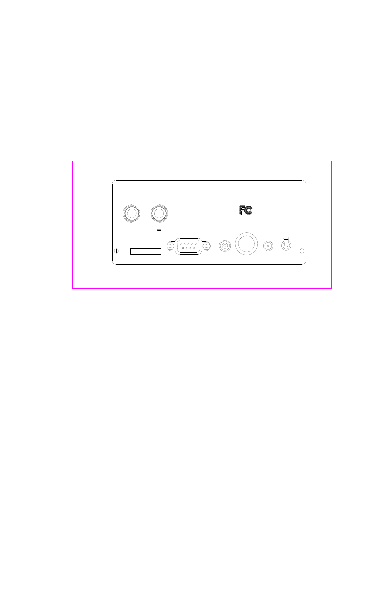
Located on the RX10K rear panel is the On/Off Power switch, a
jack for 12VDC Power Input, a Fuse housing, a connector for
attaching the Receiver Antenna, binding posts for the analog
Voltage Output, and a Com (DB9) connector for the digital data
signal. The analog Voltage Output signal has a nominal range of
±10VDC and a maximum range of ±12VDC. The digital data
signal is an RS-232 type signal for input to a PC “Com” port. See
Appendix A for the pin out and protocol.
Power
Input Antenna
12VDC 1 Amp
Fuse On
Power
Off
Com
Voltage
Output
+
Binsfeld Engineering Inc. Maple City, MI USA
(+1) 231-334-4383 www.binsfeld.com
Tested to Comply
With FCC Standards
SN:
Figure 2: Rear panel of the RX10K
CAUTION: The Power Input, Voltage Output and Com (digital
output) share a common (or ground) connection. Specifically, the
outside ring of the Power Input, the “-“ jack of the Voltage Output
and pin 5 of the Com output are all internally connected.
Care must be taken in connecting the RX10K to external
components in order to eliminate ground loop problems. Such
ground loop currents can cause errors in the output signals and
possible internal damage.
The included power supply is electrically isolated and will eliminate
any ground loop problems with the Power Input. It is
recommended that the Com (digital output) and Analog Output are
not connected to external equipment at the same time. An
exception to this rule exists when one of the two external devices
accepting the analog or digital output signal is “floating” or not
externally connected, such as battery operated voltmeter or a
laptop powered by batteries.

- 6 -
User Parameter Selection and Adjustment
The RX10K Receiver has seven user-configurable parameters.
The parameter name and value are shown on the lower line of the
display. Parameters are selected by scrolling through the
parameter menu using the SELECT ◄► (left and right) arrow
keys. The value of that parameter is adjusted using the ADJUST
▲▼ (up and down) arrow keys. The parameter name is displayed
on the left side and the value on the right. A description of the
parameter screens and possible settings follow.
Channel
The Channel parameter allows the user to change the receiving
RF channel to match the RF channel of the TX10K. There are 16
RF channels. Appendix A contains a table listing the RF channels
and their corresponding frequencies. Along with the channel
selection value, a bar graph indicating the relative RF signal
strength being received is displayed. The more “=” units, the
better the signal strength (ten is maximum).
Input
The Input parameter allows the user to simulate certain inputs
from the TX10K. These can be used to check the operation and
settings of the RX10K, even without a transmitter. The possible
values are listed below:
Input Description
Transmitter The TX10K signal is the input (normal operating
mode)
+FS Positive Full Scale input is simulated
Zero Zero level signal input is simulated
-FS Negative Full Scale input is simulated
+FS/2 Positive half scale input is simulated
-FS/2 Negative half scale input is simulated
+FS/4 Positive quarter scale input is simulated
-FS/4 Negative quarter scale input is simulated
+00328 -_____█_____+
Rx Ch: 1 ==========
+00328 -_____█_____+
Input: Transmitter

- 7 -
Filter
The Filter parameter allows the user to change the bandwidth of
the output signal. It functions as a low pass filter, meaning
frequencies above the selected value are attenuated. This allows
the user to reduce the amount of high frequency data on the
output signal (i.e., reduce noise) and effectively average the output
value. Selectable values are 500, 250, 120, 60, 30, 15, 8, 4, 1 Hz.
NOTE: Changing the Filter settings also changes the reception
error rate detection threshold. This means that using a lower Filter
setting may improve data integrity in an electrically noisy
environment (where RF interference is present).
Input AutoZero
The Input AutoZero parameter provides an easy way to
compensate the output for any offset from the gage or sensor.
When turned On ("Input AutoZero: On"), the existing input from the
TX10K becomes the input zero. Before adjusting the Gain, apply
the AutoZero to the input signal. In this way, the zero (0V) output
will not change when the Gain setting is adjusted. When the
AutoZero is off ("Input AutoZero: Off"), no offset correction is
applied to the output signal.
To turn the AutoZero On, press and hold the ADJUST ▲key for 2
seconds. To turn the AutoZero Off, press and hold the ADJUST
▼key for 2 seconds. In order for AutoZero to properly zero the
output, the displayed output number must be stable. Switching the
Filter to a lower frequency setting may help stabilize the signal to
enable an effective AutoZero. The Filter may then be returned to
its original setting for normal operation. The AutoZero function will
not work properly if there are 1) too many “Tx→Rx Data” errors, 2)
the signal from the TX10K is over or under range, or 3) the Input
parameter is not set to “Transmitter”.
+00328 -_____█_____+
Filter: 500Hz
+00000 -_____█_____+
Input AutoZero: 0n

- 8 -
Polarity
The Polarity parameter allows the user to change the polarity of
the output signal.
Gain
The Gain parameter allows the user to adjust the gain or scale
factor applied to the input signal and is reflected in the display
output, the Voltage Output signal, and the digital (RS-232) output
signal. The Transmitter Gain is displayed on the left ("Gain
T:02000 S:02000") and is changed using the RM10K Remote
Control. The System Gain is shown on the right ("Gain T:02000
S:02000") and is the parameter adjusted on the RX10K.
The Transmitter Gain is set based on the microstrain (e) range
expected during a given test (see table below; strain values
assume a Gage Factor of 2.0).
Transmitter Gain
Setting
Full Scale Strain
(Full Bridge, e)
500
±4000
1000
±2000
2000
±1000
4000
±500
8000
±250
16000
±125
Full Scale Strain corresponds to a display reading of 10000, an
analog Voltage Output value of 10 VDC, and a digital data output
of 10000. The System Gain can be adjusted from 25% to 400% of
the Transmitter Gain (i.e., ¼ to 4 times the Transmitter Gain) for
convenient output scaling. The equation below relates strain input
to Voltage Output.
+00000 -_____█_____+
Polarity: Positive
+00000 -_____█_____+
Gain T:02000 S:02000
TXconst
System
Gain
RX10K
Voltage
Output (V)
=
Measured
Strain (e)
x
Gage
Factor
x
x

- 9 -
The Transmitter constant (TXconst) is 2.5V. The Gage Factor is
specified by the gage manufacturer but is typically about 2.0. See
Appendix B for Full Scale torque and output scaling equations and
sample calculations.
Output Offset
The Output Offset allows the user to adjust the offset or “move the
zero” of the output from the RX10K. The adjustment value
displayed on the right is the actual output offset value in millivolts.
The adjustment range is from –12000mV to +12000mV (12V),
meaning the zero can be moved anywhere within the output
range.
This adjustment affects the display output, the Voltage Output
signal, and the digital (RS-232) output signal. The Output Offset
value is applied to the signal after the Gain adjustment; therefore,
the Gain adjustment may affect the zero output signal.
User Default
The RX10K parameters can be returned to their default settings.
Holding down the ADJUST ▲key while powering up the RX10K
resets the RX10K to the default values listed below.
Default Description
Rx Ch 1
Input Transmitter
Filter 500Hz
Input AutoZero Off
Polarity Positive
Gain T=S
Output Offset 0
NOTE: All settings and offsets will be retained when power is
cycled on the receiver.
+00000 -_____█_____+
0utput 0ffset: +00000
- 10 -
Signal Processing
The TX10K data signal is processed by the RX10K as follows:
1. Receive signal from TX10K
2. Check for errors and display if any detected
3. Check for simulated signal and apply if enabled
4. Apply Filter
5. Apply AutoZero
6. Apply Polarity
7. Apply Gain
8. Apply Output Offset
9. Send signal to display, voltage output, and digital output
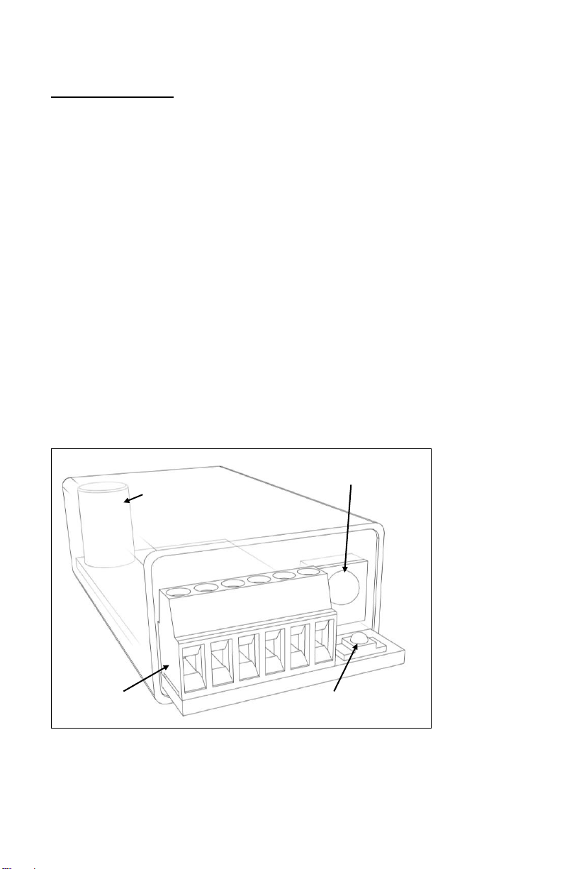
TX10K-LP-S Transmitter
The TX10K-LP-S Transmitter is encased in a small, rugged, potted
plastic housing.The TX10K-LP-S also features a Status Indicator
light, an Infrared Receiver lens, and a screw terminal block for
making power and sensor input connections.
Figure 3: TX10K-LP-S Transmitter
Infrared Receiver
Status Indicator Light
Screw
Terminal
Block
Internal Antenna

- 11 -
The TX10K can be configured even while it is installed (but not
rotating) using the RM10K Remote Control. The TX10K has
sixteen RF Channel settings and six Gain settings (500, 1000,
2000, 4000, 8000, and 16000). It can send low and high
reference signals to the RX10K: internal precision shunt resistors
simulate strain values that can be used to check calibration (refer
to Appendix A for specifications).
NOTE: Make certain the Infrared Receiver lens remains
unobstructed so that data can be received from the RM10K
Remote Control.
Status Indicator Light
When the TX10K is powered up and done initializing, it is in
normal operating mode (transmitting actual data from the sensor)
and the Status Indicator is on solid. An error is indicated when the
light is flashing, flickering or off as described below.
Indication TX10K Status
Off continuously No power applied; power polarity
is reversed; battery is dead; or the
transmitter is in Standby mode.
One flash off for ½ second A Gain or Channel command has
been received from the RM10K
Remote Control.
Another flash off for ½ second The Gain or Channel command
has been carried out.
NOTE: If there is only one flash
when changing Gain or Channel,
then the high or low limit has
been reached and cannot change
any further in that direction.

- 12 -
Fast flash (7 Hz) The input signal to the TX10K is
out of range. Reducing the Gain
will increase the input range and
may eliminate this problem.
NOTE: If the out-of-range
condition is of a short duration,
there may only be one or two
flashes.
Slow flash (2 Hz) One of the References (shunts) is
enabled. NOTE: If a signal out of
range condition occurs while the
Reference is enabled, the light
will indicate the out of range
condition (fast flash).
Flicker off once every second The power input voltage is either
too high or too low. NOTE:
Improper operation or damage to
the transmitter can occur if
operated outside its specified
power input voltage range.
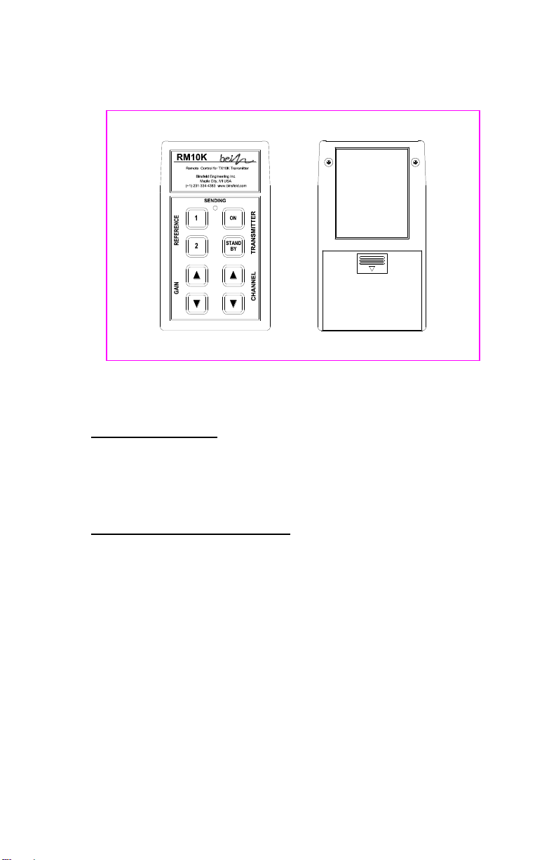
RM10K Remote Control
The handheld RM10K Remote Control allows the user to configure
the TX10K Transmitter even while it is installed. The RM10K
keypad operates similar to a common TV remote control, emitting
an infrared signal through the window on the front of the unit.
Simply point the RM10K at the Infrared Receiver on the TX10K
and press the proper key to change the configuration. Both the
Infrared Receiver lens and the window on the front of the RM10K
need to be kept clean in order to function properly.
NOTE: The RM10K is designed to transmit commands to the
transmitter when it is stationary. It will work at slow rotation
speeds, typically less than 100 rpm.
- 13 -
Figure 4: RM10K Remote Control
Battery Installation
Slide the battery access cover on the back of the RM10K
enclosure in the direction of the arrow to open. Remove the old
battery if present. Install a new 9V battery and slide the cover
back into place.
Operational Distance Settings
Typically, the RM10K needs to be within 6 inches (150 mm) of the
TX10K for the signal to be received. This normal (low infrared
power) mode is intended to reduce the possibility of inadvertently
changing the configuration of the TX10K by accidentally pressing
a key on the RM10K. It also reduces the chance of changing the
configuration of other transmitters in a multiple-transmitter
installation.
The RM10K also has a high infrared power mode. This mode is
useful when access to the TX10K is difficult or dangerous. Line-
of-sight distances of 10 feet (3 meters) or more are feasible. The
infrared signal will reflect off bright or shiny surfaces, making non-
line-of-sight operation possible in some situations.
To enable the high infrared power mode, first press and release
the TRANSMITTER ON key and then press the desired function

- 14 -
key. When the TRANSMITTER ON key is pressed, the green
SENDING light on the RM10K will come on for about 3 seconds.
The desired function key must be pressed within this 3-second
timeframe; otherwise the RM10K will revert back to normal (low
infrared power) mode. To send the ON command in high power
mode, press the TRANSMITTER ON key twice.
The Infrared Receiver on the TX10K has an automatic gain
control. Under bright light, it will become less sensitive, and the
operational distance will be decreased. If the TX10K is not
receiving commands from the RM10K, try shading the Infrared
Receiver from direct, bright light.
RM10K Key Functions
A summary of each of the RM10K key functions and indicator light
operation appears below.
TRANSMITTER ON
Brings the TX10K out of Standby mode or temporarily enables
high infrared power mode.
TRANSMITTER STANDBY
Switches the TX10K into a low-power Standby mode to conserve
the battery. No signal is transmitted while in Standby mode. The
Status Indicator light on the TX10K turns off. The TX10K ignores
all commands from the RM10K except TRANSMITTER ON.
Disconnecting and reconnecting the 9V battery or activating
TRANSMITTER ON brings the TX10K out of Standby mode.
REFERENCE 1
Activates the Reference 1 input signal or shunt resistor on the
TX10K for 5 seconds. With a 350Ωgage and 2.0 gage factor, the
value simulates input strain equivalent to 100 microstrain in the
positive direction. If this key is held down, the Reference will stay
activated. If the key is pressed again within the 5 seconds, the
Reference will remain activated for another 5 seconds (see
Appendix A.)
REFERENCE 2
Operation is the same as Reference 1 but simulates a 500
microstrain input in the positive direction with a 350Ωgage and 2.0
Gage Factor (see Appendix A).

- 15 -
GAIN ▲
Increases the gain setting of the TX10K. If the Transmitter Gain is
already at the maximum value, the Status Indicator on the TX10K
will flash only once, indicating the command was received but not
carried out.
GAIN ▼
Decreases the gain setting of the TX10K. If the gain is already at
the minimum value, the Status Indicator on the TX10K will flash
only once, indicating the command was received but not carried
out.
CHANNEL ▲
Increases the RF channel of the TX10K. If the channel is already
at the maximum value, the Status Indicator on the TX10K will flash
only once, indicating the command was received but not carried
out.
CHANNEL ▼
Decreases the RF channel of the TX10K. If the channel is already
at the minimum value, the Status Indicator on the TX10K will flash
only once, indicating the command was received but not carried
out.
SENDING Light
The SENDING light will come on for about 1 second when a key is
pressed. This indicates the RM10K is sending a signal. It is not
an indication that the TX10K has received the signal. The Status
Indicator on the TX10K or the display on the RX10K can be
monitored to confirm successful command transmission.
If the SENDING light flashes after a key is pressed, the battery in
the RM10K is low and should be replaced. If the SENDING light
does not come on at all after a key is pressed, the battery is dead
and needs to be replaced.
As mentioned in the previous section, the SENDING light will stay
on for about 3 seconds after the TRANSMITTER ON key has
been pressed. This indicates the RM10K is in high power mode,
and any command sent during the next 3 seconds will be at the
high infrared power level.

- 16 -
Multiple TX10K Transmitters
When working with multiple TX10K Transmitters in close proximity,
the Infrared Receivers may be intentionally covered with an
opaque object in order to eliminate an inadvertent configuration
change to an adjacent TX10K. Also, removing power
(disconnecting the battery) or putting the TX10K in standby mode
will prevent the RM10K from changing the configuration of a
transmitter.
Product Safety
The user assumes all risk and liability for the installation and
operation of this equipment. Each application presents its own
hazards. Typically, certain system components are strapped to a
rotating shaft. If sufficient care is not taken to properly secure
these components or accessories connected to them, they can be
flung from the shaft, causing damage to the components or to
property or persons in the vicinity. Use more than enough tape:
10 or more wraps is not too much.
Installation Procedure
The TorqueTrak 10K System is designed for ease of use. The
procedure for a typical setup on a shaft for obtaining torque
measurements is detailed in the Field Testing section below.
It is recommended that the user bench test the instrument to
become familiar with the various operational features prior to
conducting tests in the field. The BS900 Bridge Simulator and 9V
Battery Connector have been provided for this purpose. See the
Bench Testing section for details.

- 17 -
Field Testing
Although the settings of the TX10K can be changed during
operation of the system, it is best to determine the appropriate
Transmitter Gain setting for a given application prior to installation.
Refer to Appendix B for the relevant calculations.
1. Attach sensor or strain gage to the shaft (or other surface)
where the desired strain will be measured. Refer to Appendix
D for instructions on strain gage application.
2. Secure TX10K and fresh battery to shaft using fiberglass
reinforced strapping tape. Do not cover TX10K Infrared
Receiver or Status Indicator. Alternatively, hose clamps,
machined collars, or other mounting devices may be used but
avoid excessive compression.
CAUTION: Be certain all components are fixed firmly to
moving surfaces. The fiberglass reinforced strapping tape
should be wrapped around at least 10 times (5 times in each
direction) to secure the components to the shaft. The open
end of the tape should follow shaft rotation. For extra
protection, glue the end of the tape down. When finished with
your testing, cut the tape and remove the components. Avoid
the risk of being struck by an improperly secured object flung
from the machine by standing clear during operation!
NOTE 1: This method of securing the transmitter and battery
holder is for temporary use only. For long term use this tape
should be examined frequently for the effects of environmental
influences (e.g.: excessive oils) or extreme conditions (e.g.:
rapid starts/stops, high temperatures). Replace tape as
required following the notes in the “CAUTION” previously
listed.
NOTE 2: If the shaft is small (≤1” or 25 mm), balance might
be an issue. In this case, mount the TX10K and battery 180°
from each other on the shaft. The battery weighs nearly the
same as the TX10K-LP-S.
3. Connect the positive battery terminal to +PWR on TX10K and
the negative battery terminal to -PWR on TX10K. The Status
Indicator light should blink several times and then come on
solid. Secure to shaft.

- 18 -
NOTE: If testing will not begin for some time, use the RM10K
Remote Control to put the TX10K in Standby mode to save
battery life. The Status Indicator light will turn off. A fresh
battery will last for several days in this mode.
4. Cut an appropriate length of 4-conductor ribbon cable (as
short as practical to avoid unwanted electrical noise) and strip
and tin ends. Solder to gage per Appendix D or gage
manufacturer’s specification and make appropriate
connections to the TX10K terminals. Secure loose cable to
shaft.
5. Connect Receiver Antenna to Antenna connector on the rear
panel of the RX10K Receiver. Position magnetic-mount
antenna with element installed near the TX10K, typically within
10 feet (3 meters).
6. Insert connector on AC/DC adapter into Power Input jack on
the RX10K rear panel. Plug adapter into appropriate AC
power source (i.e., wall socket). Flip the RX10K power switch
to On while holding down the ADJUST ▲key.
NOTE: This resets the RX10K parameters to their default
settings. Simply turn On without holding any keys if previously
set parameter configurations are desired.
7. Turn on the TX10K with the RM10K (if needed). Confirm that
Status Indicator light is on solid. Slowly scroll through each
RX10K channel until it matches TX10K channel setting (top
line will quit flashing and bottom line will show the RF signal
strength). Change both units to desired channel and verify
adequate signal strength. If possible, rotate the TX10K
through complete range of motion to verify strong signal
reception in all orientations.
8. Scroll RX10K display to Gain parameter screen. Use the
RM10K to configure the Transmitter Gain to the appropriate
level.
9. Scroll RX10K display to Input AutoZero parameter screen.
Apply AutoZero with no load on the shaft to zero-out any initial
gage offset. Press and hold ADJUST ▲key for 2 seconds
until bottom line reads “Input AutoZero: On”. AutoZero can be
reset by turning off and then on again.
Table of contents
Other Binsfeld Transmitter manuals


