ARL5000 Operation Manual OP5000.1.1.7.R1ENG
3
1. Welcome
Sincerely thank you for buying Radar level transmitter!
This manual introduces the application, feature, function, installation and setup of Radar level transmitter level
transmitter so that users can know, install, use and maintain this instrument.
2. Overview
ARL5000 is characterized by 26G electromagnetic wave and the measurement will be not affected by the influence of
noise, water vapor, temperature, pressure, dust, gas volatilization etc. With excellent anti-interference ability, it can work
effectively in harsh environments.
Equipped with a new micro processor, ARL5000 is more ideal in rate signal analysis, processing capacity, which greatly
improves the stability and accuracy of measurement. ARL5000 features in non-contact level measurement, simple
structure and easy installation and it can be widely used in complicated working conditions such as reaction kettle, solid
liquid silo, high temperature and high pressure.
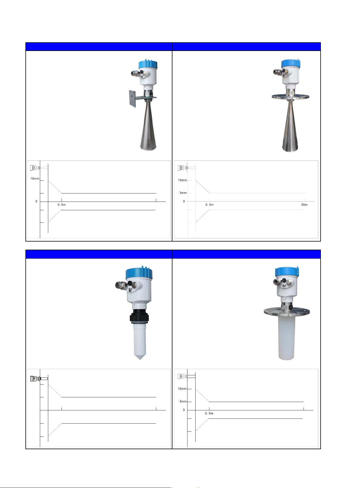
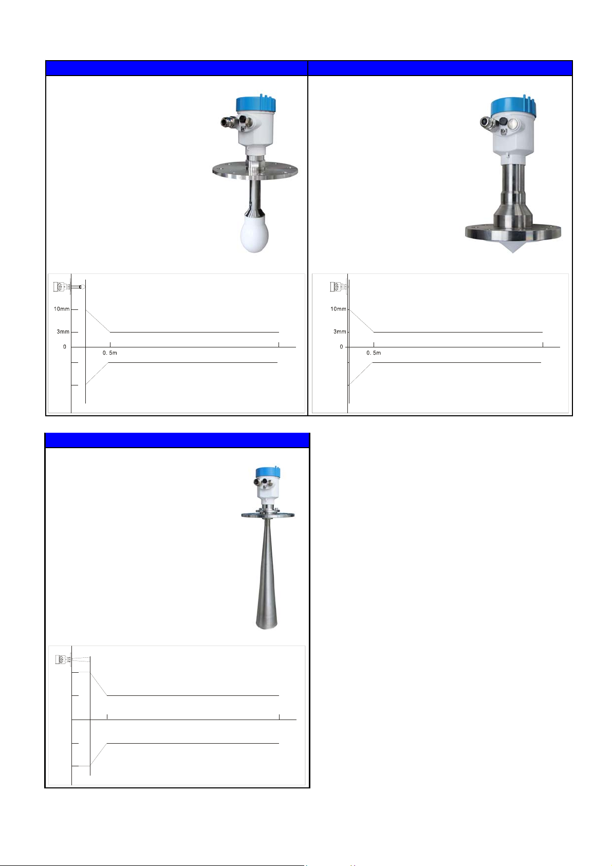
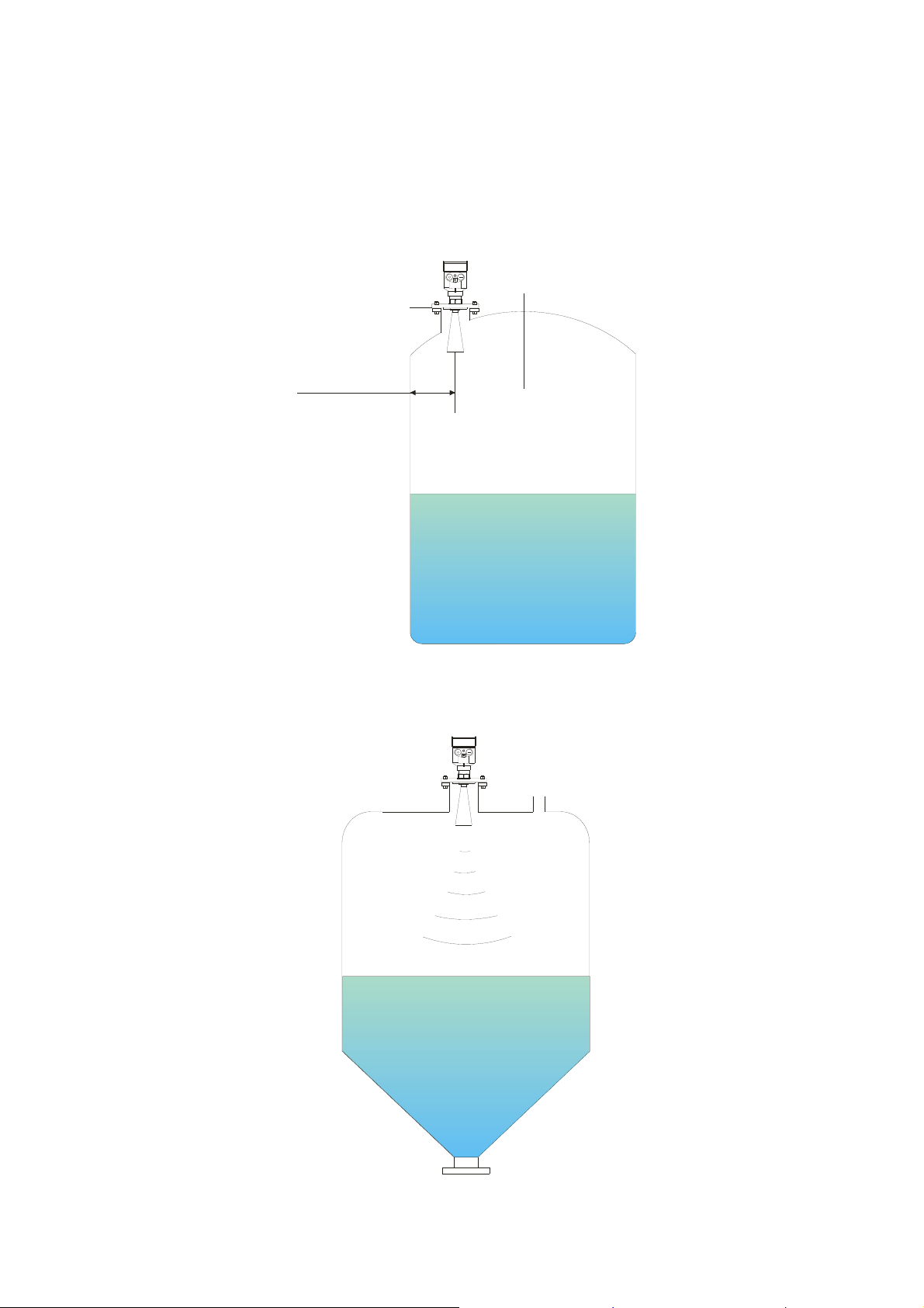
3. Measuring Principle
The narrow microwave pulses are emitted via an antenna, reflected from the measured media surface and then received
by antenna system again. The received signals are transmitted to electronic circuit and some are automatically
converted to level signals. (The process, the electromagnetic wave reaches the target and is reflected back to the
receiver, occurs instantly. because the microwave travels very fast.)
ABCD
100 00.%
0 000.%
Measurement datum plane:Screw thread Bottom and Flange Sealing Surface
Note: When the radar level is used, please make sure that the highest material level can not reach the
measuring blind are (As shown in D area).
4. Features
Non-contact radar, free of wear and pollution
Small measuring blind area, ideal for small tank measurement
Not affected by working conditions such as corrosion, foam, noise, water vapor, dust, vacuum, etc.
Small antenna, simple installation
Shorter wavelength, better reflection on inclined solid surface
High signal-to-noise ratio, excellent performance under fluctuating conditions
High frequency, ideal for the measurement of solid and dielectric constant
Small beam angle & focus energy to enhance radar echo capacity
Support HART / RS485 communication for on-site debugging
A Range Setting
B Low Lever Adjustment
C High Level Adjustment
D Blind Area