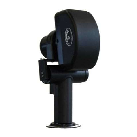
Biocare FTH-711 User manual

Page: 2 of 13
BIOCARE INTERNATIONAL
Biocare International

FTH-711 Dual Vision Thermal Scanner
Page: 3 of 13
CONTENTS
INTRODUCTION ................................................................ 2
SAFETY INFORMATION ..................................................... 4
SAFETY INFORMATION ..................................................... 5
Application Scenarios................................................... 6
Product Specifications .................................................. 6
Packing Specifications and Components.................... 7
Components List........................................................... 7
SETUP................................................................................. 8
Installation.....................................................................9
Using the Software...................................................... 10
Attention...................................................................... 12

Page: 4 of 13
BIOCARE INTERNATIONAL
SAFETY INFORMATION
-
Use the Camera only as specified inthismanual. See Table 1 for a list
of
Symbols used on the camera and in this manual.
-
A Warning identifies hazardous conditions and actions that could
cause
bodily harm or death.
-
ACautionidentifiesconditionsandactionsthatcould damagethe
Cameraor
cause permanent loss of data.

FTH-711 Dual Vision Thermal Scanner
Page: 5 of 13

Page: 6 of 13
BIOCARE INTERNATIONAL
1.APPLICATION SCENARIOS
This product is suitable for any public space, and ideal
for larger places such as: office buildings, shopping
malls, schools, airports, stations, and factories.
2. PRODUCT SPECIFICATIONS
FTH-711 is a compact thermal scanner system that alerts when multiple persons are not
wearing a mask and/or have high body temperature.
FTH-711 Dual Vision Thermal Scanner
INFRARED CAMERA
Resolution
256x192
Pixel Size
12um
NETD
<=50mK
Frame Rate
25Hz
Focal Length
3.2mm
Field Angle
56x42
VISIBLE CAMERA
Resolution
1280x720
Field Angle
FOV 80
Focal Length
4.4mm
ACCURACY OF TEMPERATURE MEASUREMENT
Measuring Range
30C ~45C
Accuracy
+-0.5C @environment tempera-
ture of 10C ~40C
Measurement
Distance
<=4m
MACHINE INTERFACE
Machine Interface
HDMI
ELECTRICAL
Power Input
AC100-240V, 50/60Hz, 0.5A
Power Output
DC 5V 3A

FTH-711 Dual Vision Thermal Scanner
Page: 7 of 13
1
2
6
4
5 7
3
3. Packing Specifications and Components.
This product comes with all you need to setup your screening process.
PACKING SPECIFICATIONS
Length
20-5/16 in. (52cm)
Width
15-1/2 in. (39cm)
Height
7-3/8 in. (19cm)
Weight
19lb (8.5Kg)
*Technical parameters are for reference only. If there are
changes, actual parameters shall prevail, without further
notice.
1
Tripod
2
Thermal Camera
3
Mouse
4
Power Supply (Monitor)
5
HDMI Cable
6
LCD Monitor
7
Power Supply (Camera)
4. Components List.

Page: 8 of 13
BIOCARE INTERNATIONAL
SECTION 02
SETUP

FTH-711 Dual Vision Thermal Scanner
Page: 9 of 13
5. INSTALLATION
(1) Remove the tripod from the storage box, and
setup to its maximum height.
(2) Place the Dual Vision Thermal Camera onto the
tripod, carefully tightening the holding screw so
that it is firmly fixed to the tripod. Make sure the
camera is facing the monitoring area, being
flush with People’s height. The angle between
the camera and the channel shall be controlled
within 45° (The traffic area needs to be well lit)
(3) Connect one end of HDMI cable to “Interface A” on
the camera/smart box rear, and the other end to the
provided LCD Monitor, or a television/monitor with
audio functions.
(4) Connect the Thermal Camera’s power supply to a
wall socket, and the input end connects to “interface
B” on the camera/smart box rear
(5) If using the provided LCD monitor, connect it to its
power supply and turn ON. The same if using and
external Television, turn ON and look for the HDMI
input that the camera is connected to.
B
A
A
LCD
Camera/smart
b

FTH-711 Dual Vision Thermal Scanner
On/off Battery
Left Button
Enter
ESC
MOUSE FUNCTION LAYOUT

Page: 10 of
13
BIOCARE INTERNATIONAL
7.USING THE SOFTWARE
(1) Starting the application
The software application will start automatically, once the
Thermal Camera/Smart BOX is powered on. To enter the
application manually, use the provided Air mouse; once in
the homepage, look for the FS265 Pro application and
press the mouse’s “trigger” button to start the software.
When the smart BOX is used for the first time or if the
application has been re-installed, the software needs to get
new permissions. In this case, the software won’t start
automatically; please select the application manually and
allow it access permission.
You can exit to the homepage at any time, by pressing the
back button on the air mouse (
right button next to scroll
dial
)
(2) Setup
(2.1) Internet
Connect the Smart BOX to the Internet, as follows:
•
Go to the homepage by pressing the back button.
(
Right button, next to the scroll dial)
•
Hover over to the settings tab and click
“Settings”.
•
Select Wi-Fi, and select ON
•
Look for your wi-fi network and enter your
password to connect.
(2.2) Date & Time
•
Still in the settings page, scroll down to “Date &
Time” and click on this tab
•
On the first line “Automatic Date & Time” should
be checked
•
A few lines down in “Select Time-zone”, check to
see it is in your correct time-zone, by clicking on the
tab, and selecting the time-zone of your city/area
•
Go back to the home-page by clicking the back
button
(right button next to scroll dial)
(3) Side by side HD Visible Light, &
Infrared Light Real-time Images
The left half of the interface, is the real-time visible-light
image. The software will recognize the human face and
display real-time body temperature. The software
supports 10-face recognition simultaneously.
The infrared light real-time image is on the right side
(4) Information Display of People Stream
Detected
On the upper right side of the interface:
•
“Detect num” - shows the total number of
people detected by the software in that day.
•
“Alarm num” - shows the number of people that
have triggered an alarm on that day (abnormal
temperature).
•
The rightmost shows the current date and time
(It cannot be set manually: automatic date & time
need to be setup in settings – See step#2)
(5) History
The detected faces and their temperatures are displayed below the
main interface. Hover the mouse to “History” and press “trigger”
button. Here in the “History’s Interface”, all the recorded images are
displayed. The boxes in the green background have normal
temperatures, while those in red have abnormal temperatures.
(5.1) Clearing the history
•To clear the history, select “Clear”.
•On the pop-up window, select “0” (# of photos retained) and
then “OK”
(5.2) Data Filtering
•In order to just filter the data or photos you want to view
for a determined date, select the “start date” and “end
date”
•In the drop-down menu of temperature, three display
modes can be selected: total, normal, or abnormal.
•Select “refresh” and the selected data will be displayed
(5.3) Exporting Data
•Click “Data Export” to export all records, and the export
results are placed in the “FS256_export” file folder.

FTH-711 Dual Vision Thermal Scanner
Page: 11 of 13
4
Gray
IronRed
Rainbow
(6) Parameter Settings
Click the “Set” button on the left, and then the “Settings Interface” will pop up.
* Warning Only - Will only alert, warnings (no mask, high temperature
All - Will alert warnings, and normal temperatures.
Category
Line No.
Setting
Description
Toggle
Visual
Camera
Settings
1 Mirror Flips camera image
180
Yes / No
2 Mask
Detection
Detects mask wearers Yes / No
3
Save Record
Saves the data
Yes / No
IR
Camera
Setting
4 Pseudo Color IR camera image color Gray / Ironred /
Rainbow
5 Temp Type Temp type Celsius / Fahrenheit
6 IR display
mode
Image display IR+visible / Visible /
Picture in Picture
System
Settings
7
Language
Language
English / Mandarin
8 Voice of Alarm Alarm alerts *
None / Warning Only /
All
9
Calibration
Calibrate temp setting
Set + or – (decimals)
10
Alarm Temp
Temp to set alarm off
Set + or – (decimals)
8
7 - 10

Page: 12 of 13 BIOCARE INTERNATIONAL
8. ATTENTION
(1) Please use the self-contained power adapter for
power supply to guarantee personal safety and
product life
(2) Store and operate in a safe and dry environment
(3) Do not remove parts arbitrarily to avoid failure
or safety accidents
(4) When the camera is not used for a long period of
time, please store it back in its container in a dry
environment

Biocare International LLC:
Biocare International LLC
Medical Device Solutions
Table of contents
Popular Scanner manuals by other brands
Douglas Lighting Controls
Douglas Lighting Controls WRS-2224 instruction manual

SICK
SICK outdoorScan3 Core I/O Mounting instructions
POSIFLEX
POSIFLEX CD-3203U Quick setup guide

Brother
Brother ADS-2200 Quick setup guide

Socket
Socket CHS 7Ci quick start guide
anhanced vision
anhanced vision acrobat-mini user manual

Oce
Oce Duplex Color Image Reader Unit-D1 user manual
Ambir
Ambir nScan 1060 Installation and setup guide
DTDAUTO
DTDAUTO MOTOSCAN Guide book

Mustek
Mustek ScanExpress 1200 FS installation guide
Uniden
Uniden BC 245XLT Trunk Tracker II operating guide
Digital Check
Digital Check TellerScan TS240 Cleaning guide


