biochrom ultrospec 7000 User manual

Ultrospec™7000/8000/9000
UV-Visible Spectrophotometers
User Manual
Biochrom US Telephone: 1-508-893-8999
84 October Hill Rd Toll Free: 1-800-272-2775
Holliston, MA Fax: 1-508-429-5732
01746-1388 support@hbiosci.com
USA www.biochromspectros.com

25061-046 Rev1
29004782UM AA 10/2011 3
1. HEALTH & SAFETY 4
1.1. General Safety 4
1.1.1. General Hazards 4
1.2. Unpacking & Installation 5
1.2.1. Instrument Connections 6
1.3. Equipment Operation 7
1.3.1. Controls and Indicators 7
1.3.2. Intended Use 7
1.3.3. Instrument Preparation 7
1.3.4. Post Run Procedures 8
1.3.5. Performance Validation 8
1.4. User Maintenance 8
1.4.1. Troubleshooting 9
1.5. Customer Support Contacts 10
1.6. Service, Repair or Return 10
1.7. Disposal 10
2. INTRODUCTION TO THE ULTROSPEC 7000/8000/
9000 SPECTROPHOTOMETER 11
3. USE WITH Datrys PC SOFTWARE 12
4. FREQUENTLY USED ICONS 13
5. PERFORMING A MEASUREMENT 14
5.1. Ultrospec 7000/8000/9000 14
6. LAMP MODE 15
7. TYPES OF BOXES 16
8. SETTINGS 17
8.1. Date and time 17
8.2. Regional 17
8.3. Data Output 18
8.4. User Interface 18
8.5. Accessories 18
8.6. Instrument Settings 18
8.7. Instrument Status 18
8.8. Instrument Information 19
8.9. Instrument Settings 19
8.10. Lamp Settings 19
9. USER ACCESS 20
9.1. Adding a user 20
9.2. Editing a user 20
9.3. Deleting a user 20
9.4. Editing user access 21
10. APPLICATIONS 22
10.1. Single Wavelength 22
10.2. Concentration via factor 23
10.3. Wavescan 24
10.4. Kinetics 25
10.4.1. Serial kinetics measurements 26
10.4.2. Parallel kinetics measurements 28
10.5. Trace Manager – Overlaying & manipulating
wavescan and kinetics files 30
10.6. Standard Curve 32
10.7. Equation Editor 34
11. LIFE SCIENCE APPLICATIONS 40
11.1. Nucleic Acid Applications 41
11.1.1. DNA, RNA & Oligo 41
11.1.2. CyDye™ DNA 43
11.1.3. TmCalculation 44
11.2. Protein Applications 47
11.2.1. BCA, Bradford, Lowry & Biuret Protein
Assays 47
11.2.2. Determination of Protein Concentration
using the BCA protein assay 47
11.2.3. Determination of Protein Concentration
using direct UV methods 50
11.2.4. Protein UV 51
11.2.5. Protein A280 52
12. SAVING AND PRINTING 53
12.1. Saving Sample Data 53
12.1.1. Internal 53
12.1.2. USB 53
12.1.3. USB csv 53
12.2. Automatic Saving 54
12.3. Manual Saving 54
12.4. Exporting Data 54
13. SAMPLE MANAGER 55
13.1. Deleting data from the internal memory 55
13.2. Accessing Sample Manager from the main
screen 56
13.3. Accessing Sample Manager from within an
application 56
13.4. Recalled files 57
14. SAVING METHODS 58
14.1. Methods saved to the internal memory 58
14.2. Methods folder 58
14.3. Renaming methods folder 59
14.4. Locking saved methods 59
14.5. Deleting saved methods 59
14.6. Backing up method folders to USB 60
14.7. Favourites folder 60
14.8. Saving methods to USB 60
15. PRINTING 61
15.1. Internal printer 61
15.2. Print via computer (PVC) 61
15.3. Bluetooth 61
15.4. Automatic printing 61
15.5. Manual printing 61
ACCESSORIES 62
Fitting 62
CELL CHARGER
63
Operation
63
Saving Method & Results
64
Incorrect Fitting
64
Using the Cell Charger to Create a
Standard Curve
64
Sipper
65
Setting Sipper defaults
65
Calibration
66
Wash Mode
66
Cleaning/Maintenance/Troubleshooting
67
TECHNICAL SPECIFICATIONS
68
CHANGING TUNGSTEN AND DEUTERIUM LAMPS
69
TABLE OF ICONS
71
GLOSSARY OF BOXES
75
LEGAL
79
CONTENTS:
29004782UM AA 10/2011 3
1. HEALTH & SAFETY 4
1.1. General Safety 4
1.1.1. General Hazards 4
1.2. Unpacking & Installation 5
1.2.1. Instrument Connections 6
1.3. Equipment Operation 7
1.3.1. Controls and Indicators 7
1.3.2. Intended Use 7
1.3.3. Instrument Preparation 7
1.3.4. Post Run Procedures 8
1.3.5. Performance Validation 8
1.4. User Maintenance 8
1.4.1. Troubleshooting 9
1.5. Customer Support Contacts 10
1.6. Service, Repair or Return 10
1.7. Disposal 10
2. INTRODUCTION TO THE ULTROSPEC 7000/8000/
9000 SPECTROPHOTOMETER 11
3. USE WITH Datrys PC SOFTWARE 12
4. FREQUENTLY USED ICONS 13
5. PERFORMING A MEASUREMENT 14
5.1. Ultrospec 7000/8000/9000 14
6. LAMP MODE 15
7. TYPES OF BOXES 16
8. SETTINGS 17
8.1. Date and time 17
8.2. Regional 17
8.3. Data Output 18
8.4. User Interface 18
8.5. Accessories 18
8.6. Instrument Settings 18
8.7. Instrument Status 18
8.8. Instrument Information 19
8.9. Instrument Settings 19
8.10. Lamp Settings 19
9. USER ACCESS 20
9.1. Adding a user 20
9.2. Editing a user 20
9.3. Deleting a user 20
9.4. Editing user access 21
10. APPLICATIONS 22
10.1. Single Wavelength 22
10.2. Concentration via factor 23
10.3. Wavescan 24
10.4. Kinetics 25
10.4.1. Serial kinetics measurements 26
10.4.2. Parallel kinetics measurements 28
10.5. Trace Manager – Overlaying & manipulating
wavescan and kinetics files 30
10.6. Standard Curve 32
10.7. Equation Editor 34
11. LIFE SCIENCE APPLICATIONS 40
11.1. Nucleic Acid Applications 41
11.1.1. DNA, RNA & Oligo 41
11.1.2. CyDye™ DNA 43
11.1.3. TmCalculation 44
11.2. Protein Applications 47
11.2.1. BCA, Bradford, Lowry & Biuret Protein
Assays 47
11.2.2. Determination of Protein Concentration
using the BCA protein assay 47
11.2.3. Determination of Protein Concentration
using direct UV methods 50
11.2.4. Protein UV 51
11.2.5. Protein A280 52
12. SAVING AND PRINTING 53
12.1. Saving Sample Data 53
12.1.1. Internal 53
12.1.2. USB 53
12.1.3. USB csv 53
12.2. Automatic Saving 54
12.3. Manual Saving 54
12.4. Exporting Data 54
13. SAMPLE MANAGER 55
13.1. Deleting data from the internal memory 55
13.2. Accessing Sample Manager from the main
screen 56
13.3. Accessing Sample Manager from within an
application 56
13.4. Recalled files 57
14. SAVING METHODS 58
14.1. Methods saved to the internal memory 58
14.2. Methods folder 58
14.3. Renaming methods folder 59
14.4. Locking saved methods 59
14.5. Deleting saved methods 59
14.6. Backing up method folders to USB 60
14.7. Favourites folder 60
14.8. Saving methods to USB 60
15. PRINTING 61
15.1. Internal printer 61
15.2. Print via computer (PVC) 61
15.3. Bluetooth 61
15.4. Automatic printing 61
15.5. Manual printing 61
ACCESSORIES 62
Fitting 62
CELL CHARGER 63
Operation 63
Saving Method & Results 64
Incorrect Fitting 64
Using the Cell Charger to Create a
Standard Curve 64
Sipper 65
Setting Sipper defaults 65
Calibration 66
Wash Mode 66
Cleaning/Maintenance/Troubleshooting 67
TECHNICAL SPECIFICATIONS 68
CHANGING TUNGSTEN AND DEUTERIUM LAMPS 69
TABLE OF ICONS 71
GLOSSARY OF BOXES 75
LEGAL 79
CONTENTS:
29004782UM AA 10/2011 3
1. HEALTH & SAFETY 4
1.1. General Safety 4
1.1.1. General Hazards 4
1.2. Unpacking & Installation 5
1.2.1. Instrument Connections 6
1.3. Equipment Operation 7
1.3.1. Controls and Indicators 7
1.3.2. Intended Use 7
1.3.3. Instrument Preparation 7
1.3.4. Post Run Procedures 8
1.3.5. Performance Validation 8
1.4. User Maintenance 8
1.4.1. Troubleshooting 9
1.5. Customer Support Contacts 10
1.6. Service, Repair or Return 10
1.7. Disposal 10
2. INTRODUCTION TO THE ULTROSPEC 7000/8000/
9000 SPECTROPHOTOMETER 11
3. USE WITH Datrys PC SOFTWARE 12
4. FREQUENTLY USED ICONS 13
5. PERFORMING A MEASUREMENT 14
5.1. Ultrospec 7000/8000/9000 14
6. LAMP MODE 15
7. TYPES OF BOXES 16
8. SETTINGS 17
8.1. Date and time 17
8.2. Regional 17
8.3. Data Output 18
8.4. User Interface 18
8.5. Accessories 18
8.6. Instrument Settings 18
8.7. Instrument Status 18
8.8. Instrument Information 19
8.9. Instrument Settings 19
8.10. Lamp Settings 19
9. USER ACCESS 20
9.1. Adding a user 20
9.2. Editing a user 20
9.3. Deleting a user 20
9.4. Editing user access 21
10. APPLICATIONS 22
10.1. Single Wavelength 22
10.2. Concentration via factor 23
10.3. Wavescan 24
10.4. Kinetics 25
10.4.1. Serial kinetics measurements 26
10.4.2. Parallel kinetics measurements 28
10.5. Trace Manager – Overlaying & manipulating
wavescan and kinetics files 30
10.6. Standard Curve 32
10.7. Equation Editor 34
11. LIFE SCIENCE APPLICATIONS 40
11.1. Nucleic Acid Applications 41
11.1.1. DNA, RNA & Oligo 41
11.1.2. CyDye™ DNA 43
11.1.3. TmCalculation 44
11.2. Protein Applications 47
11.2.1. BCA, Bradford, Lowry & Biuret Protein
Assays
47
11.2.2. Determination
of Protein Concentration
using the BCA protein assay
47
11.2.3. Determination
of Protein Concentration
using direct UV methods
50
11.2.4. Protein UV
51
11.2.5. Protein A280
52
12. SAVING AND PRINTING
53
12.1. Saving Sample Data
53
12.1.1. Internal
53
12.1.2. USB
53
12.1.3. USB csv
53
12.2. Automatic Saving
54
12.3. Manual Saving
54
12.4. Exporting Data
54
13. SAMPLE MANAGER
55
13.1. Deleting data from the internal memory
55
13.2. Accessing Sample Manager from the main
screen
56
13.3. Accessing Sample Manager from within an
application
56
13.4. Recalled files
57
14. SAVING METHODS
58
14.1. Methods saved to the internal memory
58
14.2. Methods folder
58
14.3. Renaming methods folder
59
14.4. Locking saved methods
59
14.5. Deleting saved methods
59
14.6. Backing up method folders to USB
60
14.7. Favourites folder
60
14.8. Saving methods to USB
60
15. PRINTING
61
15.1. Internal printer
61
15.2. Print via computer (PVC)
61
15.3. Bluetooth
61
15.4. Automatic printing
61
15.5. Manual printing
61
ACCESSORIES 62
Fitting 62
CELL CHARGER 63
Operation 63
Saving Method & Results 64
Incorrect Fitting 64
Using the Cell Charger to Create a
Standard Curve 64
Sipper 65
Setting Sipper defaults 65
Calibration 66
Wash Mode 66
Cleaning/Maintenance/Troubleshooting 67
TECHNICAL SPECIFICATIONS 68
CHANGING TUNGSTEN AND DEUTERIUM LAMPS 69
TABLE OF ICONS 71
GLOSSARY OF BOXES 75
LEGAL 79
CONTENTS:
16.
17.
18.
19.
20.
21.
16.1.
16.2.
16.3.
16.4.
17.1.
17.2.
17.3.
17.4.
61
61
62
62
62
63
63
64
64
65
66
67
69
73
20
20
20
20
20
21
21
22
23
24
25
27
29
31
33
39
40
40
42
43
46
46
46
49
50
51
52
52
52
52
52
53
53
53
54
54
55
55
56
57
57
57
58
58
58
59
59
59
60
60
60
60
60
60
1.1. Safety

35061-046 Rev1
29004779UM AA 10/2011 2
1. 3
3
3
2. PASSIVE ACCESSORIES 6
2.1. Single Cell Holder 7
2.2. Variable Pathlength Cell Holder 7
2.3. Water Thermostatted Cell Holder 7
2.4. Film Holder 7
2.5. Test Tube Holder 7
2.6. Peltier Controlled Fluid Circulator 8
2.6.1. General Information 8
2.6.1.1. General Warnings 8
2.6.1.2. Quality, Reliability and Safety 8
2.6.1.3. Safety Markings 8
2.6.2. Instrument Description 8
2.6.2.1. Controller front and rear panel 9
2.6.2.2. Specifications 9
2.6.2.2.1. Keypad/Display Unit 9
2.6.2.2.2. Programmable Parameters 9
2.6.2.2.3. Displayed Values 9
2.6.2.2.4. Operating Specifications 9
2.6.2.2.5. External Control Possibilities 9
2.6.2.2.6. Dimensions 9
2.6.2.2.7. Electrical data 9
2.6.2.2.8. Description of Symbols 9
2.6.2.2.9. Environmental conditions 9
2.6.2.3. User interface 10
2.6.3. Installation 10
2.6.3.1. Checking the serial number 10
4.6.3.2. Checking mains supply and fuses 10
2.6.3.2.1. Changing the Mains Voltage
Setting and Fuses 10
2.6.3.3. Instrument set-up 10
2.6.3.3.1. Start up 10
2.6.3.3.2. External Connections 11
2.6.4. Operating Instructions 11
2.6.4.1. Manual operation 11
2.6.5. Maintenance 12
2.6.5.1. Cleaning the instrument 12
2.6.5.2. Water level alarm 12
2.6.6. Troubleshooting 12
2.6.6.1. Audible alarm 12
2.6.6.1.1. Water level Alarm 12
2.6.6.1.2. Other system Alarms 12
3. ACTIVE ACCESSORIES 13
3.1. 8-Position Cell Changer 13
3.2. 5-Position Thermostatted Cell Changer 14
3.3. Sipper & Flowcell 14
3.3.1. Sipper Troubleshooting 15
3.3.1.1. Sample not being sipped
through Flowcell 15
3.3.1.2. Sample being pumped right
through Flowcell 16
3.3.1.3. Bubbles in Flowcell 16
3.3.1.4. Inconsistent readings
16
3.3.1.5. Wrong volume being sipped
16
4. INSTALLING THE INTERNAL PRINTER
17
5.
19
Page finder
Accessories Appendix
3
14
14
15
INSTALLATION
1.
29004779UM AA 10/2011 2
1. 3
3
3
2. PASSIVE ACCESSORIES
6
2.1. Single Cell Holder
7
2.2. Variable Pathlength Cell Holder
7
2.3. Water Thermostatted Cell Holder
7
2.4. Film Holder
7
2.5. Test Tube Holder
7
2.6. Peltier Controlled Fluid Circulator
8
2.6.1. General Information
8
2.6.1.1. General Warnings
8
2.6.1.2. Quality, Reliability and Safety
8
2.6.1.3. Safety Markings
8
2.6.2. Instrument Description
8
2.6.2.1. Controller front and rear panel
9
2.6.2.2. Specifications
9
2.6.2.2.1. Keypad/Display Unit
9
2.6.2.2.2. Programmable Parameters
9
2.6.2.2.3. Displayed Values
9
2.6.2.2.4. Operating Specifications
9
2.6.2.2.5. External Control Possibilities
9
2.6.2.2.6. Dimensions
9
2.6.2.2.7. Electrical data
9
2.6.2.2.8. Description of Symbols
9
2.6.2.2.9. Environmental conditions
9
2.6.2.3. User interface
10
2.6.3. Installation
10
2.6.3.1. Checking the serial number
10
4.6.3.2. Checking mains supply and fuses
10
2.6.3.2.1. Changing the Mains Voltage
Setting and Fuses
10
2.6.3.3. Instrument set-up
10
2.6.3.3.1. Start up
10
2.6.3.3.2. External Connections
11
2.6.4. Operating Instructions
11
2.6.4.1. Manual operation
11
2.6.5. Maintenance
12
2.6.5.1. Cleaning the instrument
12
2.6.5.2. Water level alarm
12
2.6.6. Troubleshooting
12
2.6.6.1. Audible alarm
12
2.6.6.1.1. Water level Alarm
12
2.6.6.1.2. Other system Alarms
12
3. ACTIVE ACCESSORIES
13
3.1. 8-Position Cell Changer
13
3.2. 5-Position Thermostatted Cell Changer
14
3.3. Sipper & Flowcell
14
3.3.1. Sipper Troubleshooting
15
3.3.1.1. Sample not being sipped
through Flowcell
15
3.3.1.2. Sample being pumped right
through Flowcell
16
3.3.1.3. Bubbles in Flowcell
16
3.3.1.4. Inconsistent readings 16
3.3.1.5. Wrong volume being sipped 16
4. INSTALLING THE INTERNAL PRINTER 17
5. 19
Page finder
4
5
5
5
5
5
6
6
6
6
6
6
7
7
7
7
7
7
7
7
7
7
7
8
8
8
8
8
8
8
9
9
9
10
10
10
10
10
10
10
11
11
12
12
13
13
14
14

45061-046 Rev1
29004782UM AA 10/2011 4
1. HEALTH & SAFETY
1.1.1. General Hazards
There a number of warning labels and symbols on your instrument. These are there
to inform you where a potential danger exists or particular caution is required. Before
commencing installation, please take time to familiarize yourself with these symbols
and their meaning.
This instrument is intended for use by individuals trained in and familiar with the use
of spectrophotometers and their associated hazards. In the event of a malfunction
or hazard occurring, the user responsible shall disconnect the unit from power and
isolate for decontamination and /or repair.
This instrument is subject to the following hazards:
High voltages exist inside the unit. Repair and maintenance should only be carried out by individuals trained
specifically to work on these instruments.
The UV source contained within the unit generates a light beam that traverses the sample chamber and is
accessible in the lamp chamber. Under normal use the lamp beam is confined within the instrument. The unit
should not be operated with the sample chamber lid open or the lamp housing lid removed. Prolonged exposure to
the beam may cause permanent eye damage.
1.1 Safety

55061-046 Rev1
There are no bio-hazardous materials within the unit; however this unit could be used with bio-hazardous samples.
Before using the instrument the customer should have in place decontamination procedures designed to protect
laboratory workers from occupationally acquired infections. The sample chamber cell holders are removable and
may be decontaminated using the appropriate disinfectant for the bio-hazard in question, rinsed with distilled
water and then allowed to dry. The sample chamber and exterior may be wiped with a suitable disinfectant
cleaning wipe.
• Decontamination.Equipmentreturnedforrepairshouldincludeanappropriatedecontaminationcertificate.
• Itistheresponsibilityofthecustomertoensurethattheuseroftheequipmentisprovidedwithasafeworking
environment.
• AnychemicalsusedinAnalysesshouldbeused,storedanddisposedofinaccordancewithmanufacturer’s
guidelines and local safety regulations.
• ToxicFumes.Efficientlaboratoryventilationmustbeprovidedwhenworkingwithvolatilesolventsortoxic
substances.
• Wastedisposal.Disposalofsomesolventsandchemicalsmaybeclassedashazardouswasteandmustbe
dealt with in accordance with local regulatory practice.
• Personalprotectiveequipment.Thisisnotrequiredtooperatetheunitbutthesamplesmeasuredmayrequire
PPE. A local risk assessment should be carried out.
This equipment may be connected and controlled from a PC. To preserve the integrity of the measuring equipment
it is essential that the attached PC itself conforms to basic safety and EMC standards and is set up in accordance
withthemanufacturers’instructions.IfindoubtconsulttheinformationthatcamewithyourPC.Incommonwith
all computer operation the following safety precautions are advised.
• Toreducethechanceofeyestrain,setupthePCdisplaywiththecorrectviewingposition,freefromglareand
with appropriate brightness and contrast settings.
• Toreducethechanceofcrosscontaminationfrombiologicalsamples,useappropriatepersonnelprotection
measures and disinfectant wipes on keyboard and mouse.
Care must be taken when handling all heated accessories.
1.2. Unpacking & Installation
• These instruments weigh approximately 18.5 kg. Follow your local regulations for
safe handling and lifting of this equipment.
• Inspect the instrument for any signs of damage caused during transit. If any
damage is discovered. Do not use the instrument and report the problem to your
supplier.
• The instrument must be placed on a stable, level bench or table capable of taking
its weight with sufcient space around the instrument for ventilation to circulate
freely.
• Ensure your proposed installation site conforms to the environmental conditions for
safe operation.
• Indoor use.
• 5 to 40°C.
• Maximum relative humidity 90% up to 31°C decreasing linearly to 50% at 40°C.
• Extremes of temperature may require re-calibration of the unit for optimum
performance.
• If the instrument has been stored in a cold environment then it should be allowed
to come to thermal equilibrium for 2 to 3 hours before operation so that start up
calibration is not compromised by condensation.
• The equipment must be connected to the local supply outlet using the provided
power cables. It can be operated from 90 to 264 V~ 50 or 60 Hz.
• Replace power inlet fuses only with the same type and rating as follows:

65061-046 Rev1
29004782UM AA 10/2011 6
1.2.1. Instrument Connections
USB B receptacle
for connection to PC
Connector for external
powered accessories
On / Off switch
Fuse holder
Mains inlet
Internal accessory connector
• For Deuterium/Tungsten units T 1.6 A H 250 V AC (Anti-Surge, High breaking
capacity).
• For Xenon units T 1.6 A H 250 V AC (Anti-Surge, High breaking capacity).
• Power rating is:
• 100 VA for Xenon units.
• 150 VA for Deuterium/Tungsten units.
• The instrument should be positioned so that the power cable may be readily
removed in the event of a hazard or malfunction occurring.
• Site the instrument in an atmosphere free from dust and corrosive fumes.
• Use the on/off switch on the left hand side of the instrument. The instrument
will automatically perform some start up self diagnostic checks on switch on.
Please wait for these to nish before attempting to use the equipment.
USB A plug for USB memory sticks
(Ultrospec 7000, 8000 and 9000 stand alone units only)

75061-046 Rev1
Ultrospec
29004782UM AA 10/2011 7
1.3. Equipment Operation
1.3.1. Controls and Indicators
1.3.2. Intended Use
The instrument is intended to be used by scientists and technicians who possess
basic laboratory and technical skills and have the knowledge and understanding
of the hazards involved, with the unit and the samples used, to operate it in a safe
manner.
e.g. DNA/RNA/Oligo concentration and purity measurements as well as protein
determinations.
1.3.3. Instrument Preparation
• Switchontheunitandallowittofinishitsstartupcalibration.
• Bestperformanceisobtainediftheinstrumentisallowedtowarmupandstabilize
for at least 30 minutes.
• IfapplicableconnecttheunittoaPCusingaUSBcableandrefertotheonline
help and user manual.
• Selecttheappropriateapplicationormethod.
• Whererelevant,setuptheapplicationparametersforthesample.
• ForDeuterium/Tungstenunitsaprecisionmodeisavailable.Tousethismode
enter the desired application and switch to precision mode.
• Selectcuvettecellstouse.Itisimportanttousecellsofthecorrecttype.Most
samples are measured using a standard 10 mm path length cell. Special cells and
accessories are available for larger or smaller path lengths and sample volumes.
It is important to use cells of the correct type. Some cells absorb UV and are not
suitable for UV sample measurement. Cells used for samples should be free from
dust, residue or scratches.
USB LED
This indicates that
the instrument is
writing to the USB
memory stick. The
memory stick must
not be removed
whilst this LED is on.
POWER/STATUS INDICATOR LED
The LED indicates the status of the instrument.
Orange - during start up and calibration
Green - instrument is on and passed start up
calibration tests
Red - instrument is on and has failed start up
calibration tests
e.g. DNA/RNA/Oligo concentration and purity measurements as well as
protein determinations

85061-046 Rev1
• Beforepreparingsamplesandsamplereferenceblanks,youmustbefamiliarwith
hazards arising from handling the sample materials and where necessary observe
local regulatory practice, personnel protection equipment and measures designed
to ensure your safety.
• Preparethesampleblanks(references).Areferenceistypicallythesolutionthat
the sample is dissolved in. For Dual beam units the reference may be placed in the
reference path or a separate sample reference may be made by first placing the
reference in the sample path and performing a reference measurement.
• Preparethesamplesolutions.Thesamplesolutionwouldnormallycomprisethe
sample under test dissolved in the reference solution.
• Whenplacingthecellsintheequipmentensurethecellisorientatedsothatthe
light energy will pass through the cell.
• ForfurtherinformationonrunningapplicationsandmethodsrefertoChapter“10.
APPLICATIONS”.
1.3.4. Post Run procedures
• Emptycuvettecellsofsampleandrinsewithdeionizedwater.
• Cleancuvettesperiodicallywithcommerciallyavailablecleaningsolutionordilute
detergent solution followed by a thorough rinse in deionized water.
• Notethatsomesamplesandsolventsmaybeclassifiedashazardousorbio
hazardous waste. The disposal of such substances must be carried out in
accordance with local regulatory practice.
1.3.5. Performance Validation
Good laboratory practice recommends that the unit is periodically checked for
optical performance.
• Switchonvalidationchecks.Whentheunitispoweredupitperformswavelength
accuracy and lamp energy checks. Once complete the unit will beep and show a
green on light.
• Periodicallywavelength,straylightandabsorbanceshouldbecheckedtoensure
the unit is performing to specification. Deterioration in performance may indicate
that the instrument needs servicing or that a poor baseline has been saved.
Performance validation can be carried using traceable reference materials.
1.4. User Maintenance
• OtherthantheTungstenandDeuteriumlampsincertaininstrumentsthereareno
user serviceable parts in this equipment.
• Topreventcontamination:
•Cellholdersandaccessoriesshouldberemovedandcleanedwithcommercially
available cleaning solution or dilute detergent followed by a thorough rinse in
deionized water. Allow to dry thoroughly before use.
•Caseworkandthesamplecompartmentmaybewipeddownwithcommercially
available disinfectant wipes.
• The lamps used in the unit age over time and less energy will be available to pass
through the sample. Where energy has fallen to around 50% of the installation
energy you are advised to have the lamps changed. Deuterium and Tungsten
lamps may be replaced by the user, see section 20 for details. Xenon lamp
replacement can only be carried out by a qualied service engineer.
95061-046 Rev1
If the equipment is operated in a manner not specified, then the protection provided by the equipment may be
impaired and the instrument warranty withdrawn.
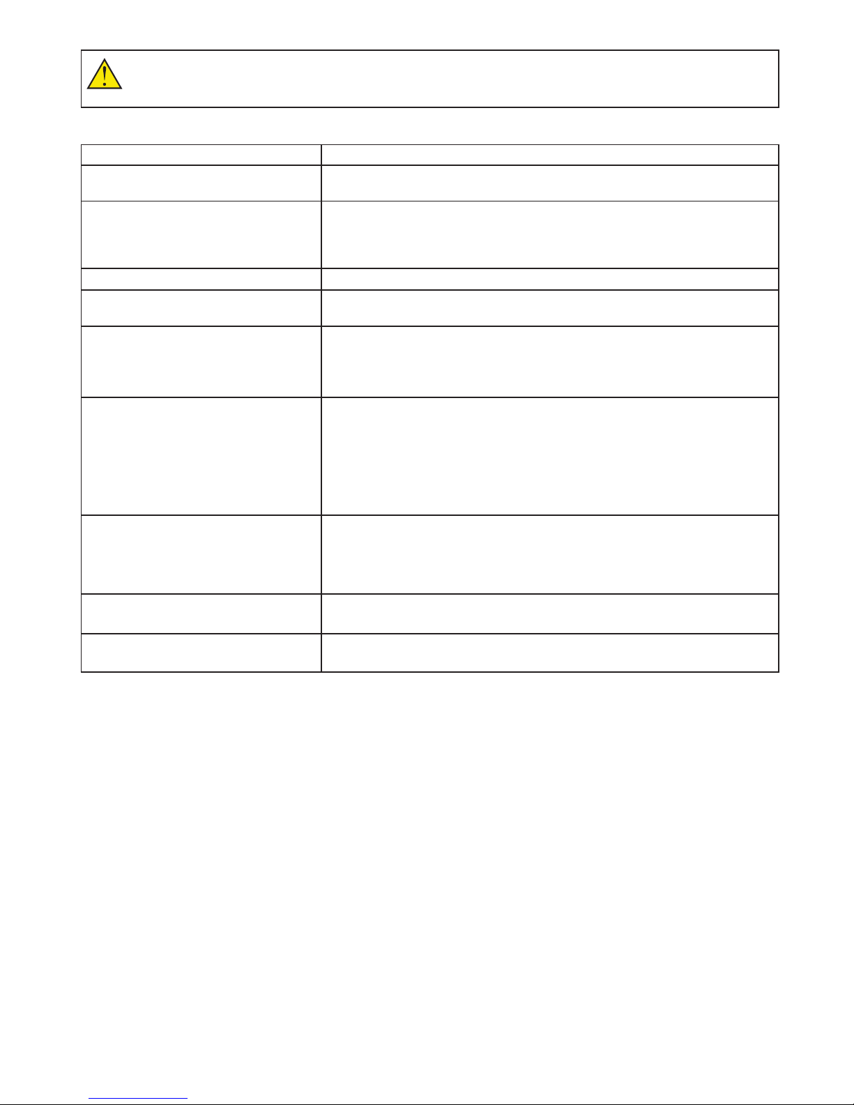
1.4.1. Troubleshooting
PROBLEM POSSIBLE CAUSE
Start up calibration fails Check sample (and reference) beam is clear before switch on. Possible optical
failure, contact service support.
Negative absorbance reading Check that sample and reference cells have not been swapped
Check sufficient height of sample solution (beam height is nominally 15 mm
above the cell base for normal measurements and it is recommended that it be
filled to 20 mm above the base).
Unexpected results Check for bubbles in solution.
Start up calibration fails Check sample (and reference) beam is clear before switch on. Possible optical
failure, contact service support.
Negative absorbance reading Check that sample and reference cells have not been swapped.
Check sufficient height of sample solution (beam height is nominally 15 mm
above the cell base for normal measurements and it is recommended that it be
filled to 20 mm above the base).
Absorbance values higher than expected Check for use of incorrect cell type.
Check cells are free from finger prints.
Check cells for contamination.
Check cell orientation.
Check reference used.
Possible optical alignment problem, contact service support.
Absorbance value lower than expected Check sufficient height of sample solution.
Check sample and reference are not the same.
Check sample compartment lid is properly closed.
Possible stray light issue, contact service support.
Instrument will not reference Check orientation of cuvette.
Check for use of incorrect cell type.
Poor reproducibility with nucleic acid
analysis
Check for particles, try using background correction.
Try increase in concentration.
105061-046 Rev1
29004782UM AA 10/2011 10
1.5. Customer Support Contacts
Note: If you experience any problems with your instrument, please refer to section
“1.4.1. Troubleshooting”.
If you require further assistance, please contact customer support :
1.6. Service, Repair or Return
Good laboratory practice recommends that the unit be periodically serviced to
ensure the unit is suitable for purpose. It is recommended that the instrument be
serviced annually. You can arrange this through your distributor. Prior to Inspection,
Servicing, Repair or Return of Medical and Laboratory Equipment the unit must be
decontaminated.
A returns policy operates on this equipment. Before returning the equipment to the
distributor or manufacturer:
1.7. Disposal
Decontamination
In use this product may have been in contact with bio-hazardous materials. Before disposal all accessories should
be removed and thoroughly cleaned in disinfectant and then rinsed with distilled water. All outside surfaces and
sample chamber walls must be wiped down with disinfectant wipes suitable for purpose.
WEEE
A label with a crossed-out wheeled bin symbol indicates that the product is covered by the Waste Electrical and
Electronic Equipment (WEEE) Directive and is not to be disposed of as unsorted municipal waste. Any products
marked with this symbol must be collected separately and in accordance with local regulatory practice.
visit: www.biochromspectros.com
or email: [email protected]
or telephone: (US) 1-800-272-2775 (UK) +44 1223 423723
1-508-893-8999 +44 1223 427888
Please contact [email protected] for the correct paperwork and instructions.
29004782UM AA 10/2011 10
1.5. Customer Support Contacts
Note: If you experience any problems with your instrument, please refer to section
“1.4.1. Troubleshooting”.
If you require further assistance, please contact customer support :
1.6. Service, Repair or Return
Good laboratory practice recommends that the unit be periodically serviced to
ensure the unit is suitable for purpose. It is recommended that the instrument be
serviced annually. You can arrange this through your distributor. Prior to Inspection,
Servicing, Repair or Return of Medical and Laboratory Equipment the unit must be
decontaminated.
A returns policy operates on this equipment. Before returning the equipment to the
distributor or manufacturer:
1.7. Disposal
Decontamination
In use this product may have been in contact with bio-hazardous materials. Before disposal all accessories should
be removed and thoroughly cleaned in disinfectant and then rinsed with distilled water. All outside surfaces and
sample chamber walls must be wiped down with disinfectant wipes suitable for purpose.
WEEE
A label with a crossed-out wheeled bin symbol indicates that the product is covered by the Waste Electrical and
Electronic Equipment (WEEE) Directive and is not to be disposed of as unsorted municipal waste. Any products
marked with this symbol must be collected separately and in accordance with local regulatory practice.

115061-046 Rev1
2. INTRODUCTION
TO THE Ultrospec
7000/8000/9000
SPECTROPHOTOMETER
The Biochrom Ultrospec 7000/8000/9000 are a range of standalone, easy to use,
dual beam UV-visible spectrophotometers with high resolution color touch screens.
All spectrophotometers offer a comprehensive range of spectrophotometric and life
science applications.
A spectrophotometer is an optical arrangement that is designed to pass light
energy through a sample. The reduction of transmittance of the light energy and
corresponding absorbance peaks, caused by the sample under test, can be used
in a qualitative way to determine sample composition or in a quantitative way, by
comparing with known concentration standards, to determine the concentration of a
sample. In other types of studies the tracking of absorbance over time can be useful
to study chemical reactions and biological processes.
The Ultrospec 7000/8000/9000 range of spectrophotometers are designed to
produce light energy from the far ultraviolet through visible light in the range
190 to 1100 nm. Many materials, and in particular solutions of materials will
absorb light energy within this region. This makes the Ultrospec 7000/8000/9000
spectrophotometers applicable to a wide range of market sector needs including
applications in Life sciences, clinical, pharmaceutical, cosmetics, food & drink,
agricultural, industrial, environmental, toxicology, water treatment and teaching.
There are a large number of published methods and assays available for these.
The icons described throughout this manual use the names quoted in Chapter “20.
TABLE OF ICONS”, if you are unsure of any of their functions please refer to this
section.
For detailed descriptions of the functions of parameter boxes please refer to Chapter
“21. GLOSSARY OF BOXES”.
Note: Throughout this manual all screen shots are shown on a white background,
this is purely for illustrative purposes.

125061-046 Rev1
3. USE WITH Datrys PC
SOFTWARE
When connected to a PC the Ultrospec 7000/8000/9000 spectrophotometers can
be controlled using the Datrys PC software package. Operation using Datrys PC
software is described in the Datrys user manual or Datrys help le.

135061-046 Rev1
29004782UM AA 10/2011 13
4. FREQUENTLY USED
ICONS
Button Name Function
Forward
arrow Advances to the next screen in a sequence
Back arrow Returns to the previous screen in a sequence
Tick Confirms selection/entry. Saves and exits
Cross/exit Exit without saving
Buttons On The Sample Measurement Screen
Take
reference Performs a reference measurement
Take
measurement Performs a sample measurement
Options arrow Opens the options menu on the sample measurement
screen
Buttons On The Options Menu
Method
parameters
Takes the user from the sample measurement screen to
the first method parameter screen
Save data Allows the user to manually save sample data to a
specified location.
Save method Allows the user to save the current method parameters to
the internal memory or a USB stick
Print Prints the sample data from the specified printer
Auto print Toggles auto print on and off
Sample
Manager Accesses Sample Manager
Trace
Manager Accesses Trace Manager (wavescan and kinetics only).

145061-046 Rev1
29004782UM AA 10/2011 14
5. PERFORMING A
MEASUREMENT
5.1. Ultrospec 7000/8000/9000
The Ultrospec 7000/8000/9000 are dual beam UV/visible spectrophotometers
that contain cell holders for both samples (situated at the front of the cell
chamber) and references (situated at the back of the cell chamber). As dual beam
spectrophotometers continually reference against the reference cell holder it is
possible to perform measurements in one of three ways.
To reference against air:
1. Insert a cuvette containing the sample solution in the sample cell holder, ensure
the reference cell holder is empty and close the sample chamber lid.
2. Press take measurement.
3. Repeat until all sample data has been collected. See the section Saving and
Printing for post measurement options.
To reference against a solvent:
1. Insert a cuvette containing the sample solution in the sample cell holder, insert a
cuvette containing the solvent in the reference cell holder and close the sample
chamber lid.
2. Press take measurement.
3. Repeat until all sample data has been collected. See the section Saving and
Printing for post measurement options.
Note: This methodology is used throughout the user manual.
To correct for both solvent and cell effects (simulate matched cuvettes):
1. Insert cuvettes containing the solvent in both the sample and reference cell
holders and close the sample chamber lid.
2. Press take reference.
3. Remove the cuvette containing solvent from the sample cell holder, empty out the
solvent and replace with the sample solution.
4. Insert the cuvette containing the sample solution in the sample cell holder and
close the sample chamber lid.
5. Press take measurement.
6. Repeat steps 4 and 5 until all sample data has been collected. See the section
Saving and Printing for post measurement options.
Note: This methodology ensures the most accurate measurements.
UV-Visible

155061-046 Rev1
29004782UM AA 10/2011 15
6. LAMP MODE
When creating a method using an Ultrospec 7000/8000 or 9000 spectrophotometer
the user will have the option of setting the Lamp Mode to Precision or Pulse. These
modes are described below.
Precision
Precision Mode is used for applications requiring the most accurate measurements.
Both the Tungsten and Deuterium lamps will remain permanently switched on.
Pulse
Pulse mode is used to help preserve lamp life and reduce running costs as the
Tungsten and Deuterium lamps will be switched off after 15 minutes of inactivity.
Note:AstheUltrospec7000usesaXenonlamp,measurementscanonlybemadein
pulse mode.
165061-046 Rev1
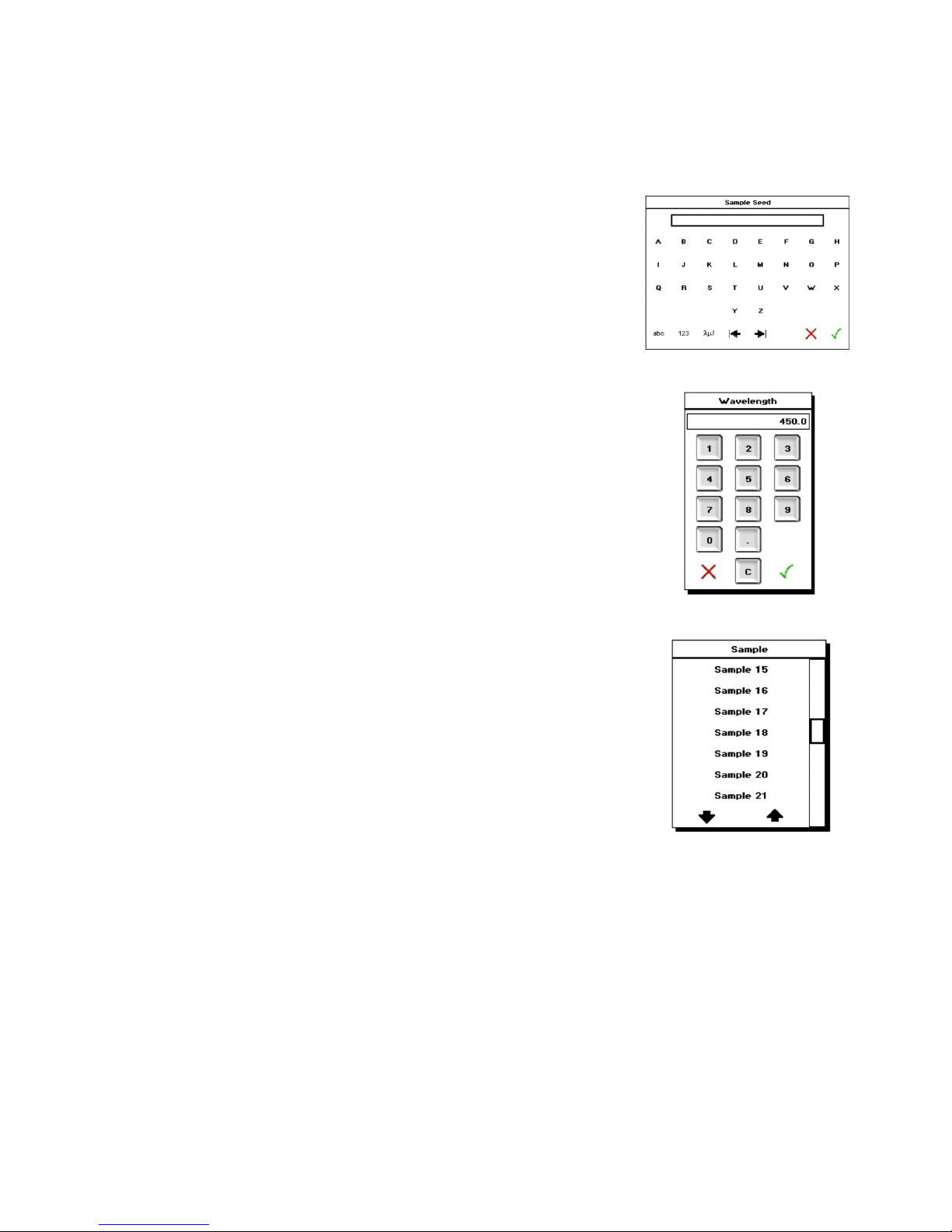
7.TYPESOFBOXES
Alphanumeric Text Entry
The alphanumeric text entry box allows the user to enter letters, numbers and
symbolsbypressingtheabc,123andλμ!buttons,respectively.Itispossibleto
toggle between upper and lower case letters and through a list of symbols by
pressingtheabcandλμ!buttonstwice.
Note: The layout of the screen is dependent on the text entry mode set under User
Interface in Settings.
Numeric Entry
The numeric entry box allows the user to include numbers in the method
parameters. Depending on the numeric box selected it may be possible to add both
positive and negative numbers.
Combo Box
Where there are greater than two options, the user will be presented with a combo
box listing all of these. If there are greater than 8 options the user can scroll
through these using either the page up and page down arrows or the scroll bar.
Note: If a box only contains two options i.e. On or Off, pressing this box will toggle
between the options and not produce a combo box.
Biochrom Ultrospec instruments use different kinds of boxes for parameter selection and
entry. These include:
175061-046 Rev1
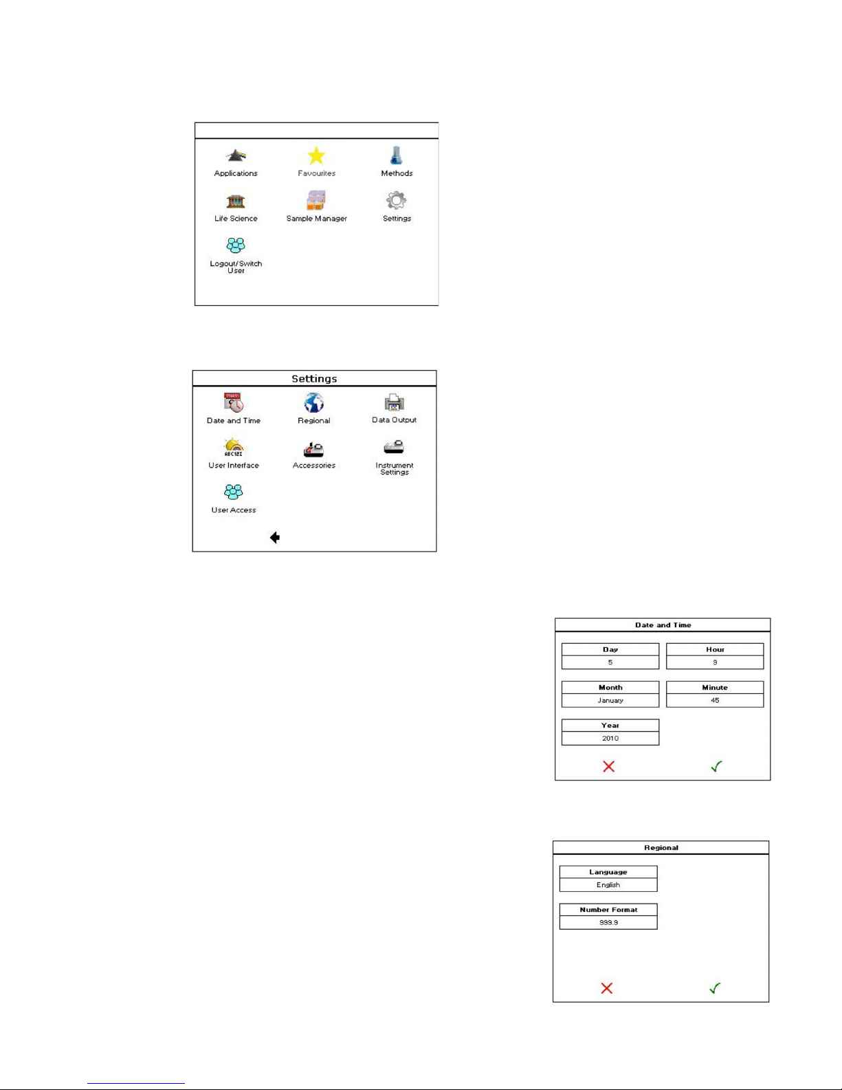
8. SETTINGS
8.1. Date & Time
8.2. Regional
Settings are accessed via the Settings button on the main screen (see below).
Note: When User Access Is turned on the Settings option will only appear on the
main screen for users with Administrator or Supervisor privileges.
The Ultrospec 7000/8000/9000 will arrive with the US EST and date set. This can be
changed by pressing the Date and Time button.
After the desired date and time have been entered, select the tick to save and exit
or the cross to exit without saving.
The Ultrospec 7000/8000/9000 will arrive with the language set to English. This can
be changed by pressing the Language button; the options are English, French,
German, Spanish, Chinese and Japanese.
To save any alterations press the tick, to exit without saving press the cross.

185061-046 Rev1
29004782UM AA 10/2011 18
8.3. Data Output
This is the default saving and printing settings that will be used in all application
method parameters.
8.4. User Interface
Allows the user to set the desired brightness level of the screen, the alphanumeric
text entry mode and the duration after which the screensaver will be displayed (if
required).
8.5. Accessories
Displays accessories that are fitted to the instrument and allows the user to set the
desired accessory parameters. For specific details see the Accessories section.
8.6. Instrument Settings
The following options are included under instrument settings:
This displays the current status of the instrument.
8.7. Instrument Status

195061-046 Rev1
Displays the serial number, user-interface (UI) version, build and release dates and
instrument control (IC) version.
Instrument Settings allows the user to:
1. Collect a new, temporary baseline. This will be stored until the instrument is
switched off.
2. Save the temporary baseline. This will become the permanent baseline and be
stored until overwritten.
3. Restore the original baseline. If measurements show the temporary baseline to
be poor quality the permanent baseline can be restored.
Note: Using the Ultrospec 9000 the bandwidth at which the baseline is measured is
selected by pressing the Bandwidth box
Displays the current lamp status and allows the user to reset lamp life (Tungsten
and Deuterium lamps only).
To exit at any time press the exit button located in the bottom right hand corner.
8.8. Instrument Information
8.9. Instrument Settings
8.10. Lamp Settings
205061-046 Rev1
29004782UM AA 10/2011 20
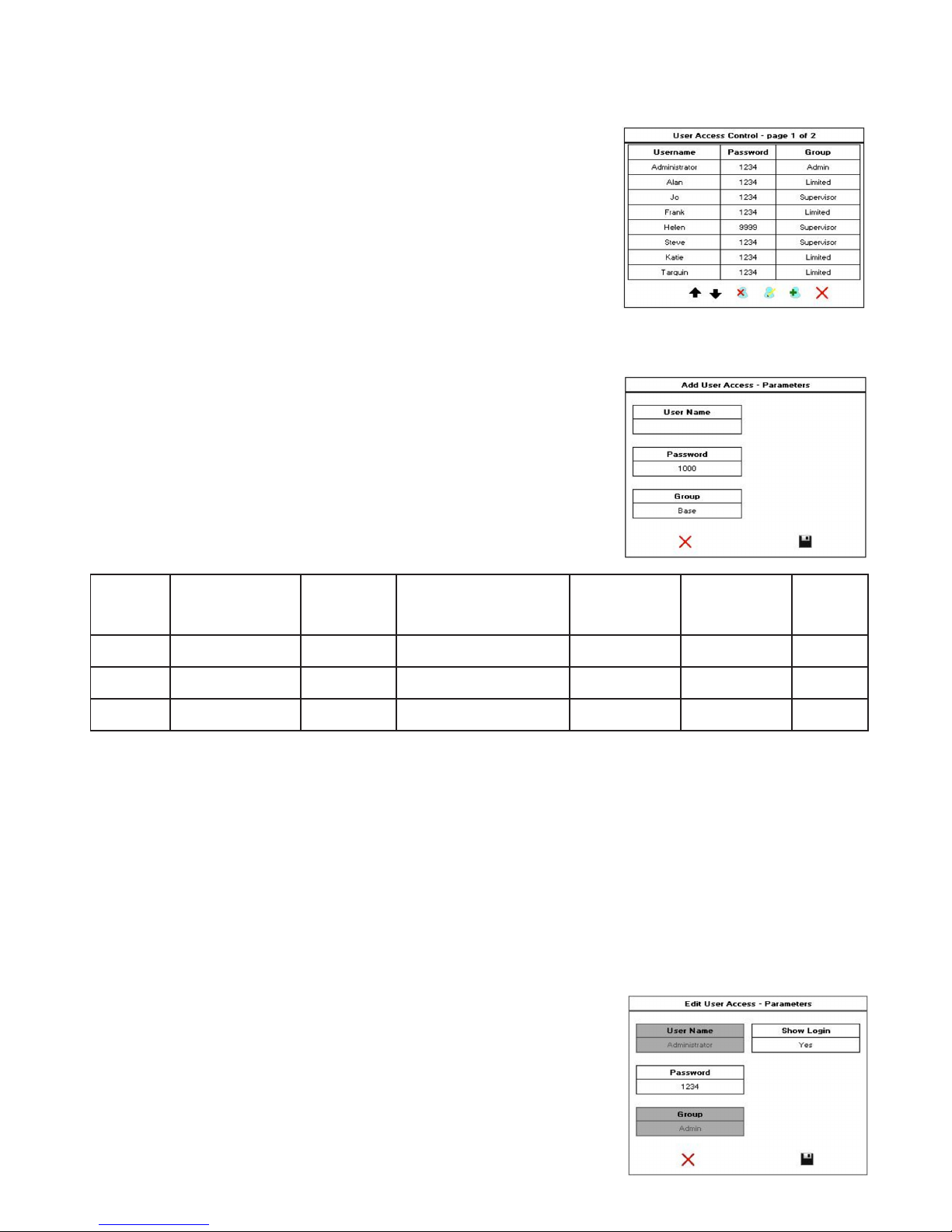
9. USER ACCESS
The Ultrospec 7000/8000/9000 have the option to assign users different access
rights. These are set via the user access button.
Note: User access is only available to users who have administrator privileges.
9.1. Adding a user
Toaddanewusertotheinstrument,pressthe‘Adduser’button.TheUltrospec
7000/8000/9000 can store up to 16 individual users. Each user is given a user
name (using alphanumeric entry), a 4-digit password and assigned to one of three
user groups depending on the access level they require. The table below outlines
the features each user group can access.
User
Group
Run Applications
& Saved Methods
Save Sample
Data
Delete Sample Data
from the instrument’s
memory
Save Methods
Access Settings
Menu
Access
User
Settings
Limited 3 3 7 7 7 7
Supervisor 3 3 3 3 7 7
Admin 3 3 3 3 3 3
9.2. Editing a user
Toeditauser’sdetails,highlightthedesireduserandpressthe‘Edituser’icon.This
allows the username, password and user group to be edited/updated as above.
9.3. Deleting a user
To delete a user from the instrument, highlight the desired user and press the ‘Add
user’icon.Anymethodsordatacreatedbythisuserwillnotbedeleted.Note:Itisnot
possible to delete the default administrator account.
9.4. Editing User Access
To disable user logins and user access, highlight the default administrator account
andpressthe‘EditUser’icontodisplaythescreenright.
Note:WithShowLoginsettoNotheinstrumentwillnotdisplaythe‘SwitchUser’
button on the main screen and the instrument will always be in Administrator mode.
This manual suits for next models
2
Table of contents
Other biochrom Medical Equipment manuals

Popular Medical Equipment manuals by other brands


Theratrac Pro
Theratrac Pro LT100 instructions

PLUSOPTIX
PLUSOPTIX A12C Short manual

Auxilab
Auxilab MiniFuge-GD06 Operation and maintenance manual

NuSight Medical
NuSight Medical NuLids quick start guide

Fillauer
Fillauer K2 Foot product manual

ABTECH SAFETY
ABTECH SAFETY SLIXRR Instruction & Maintenance Manua


