BioCool BIO Series User manual

BIOseries
ASSAMBLED IN SPAIN
Version v. /
YEARS
GUARANTEE
STRUCTURAL
YEARS
GUARANTEE
COMPONENTS
YEARS
GUARANTEE
ANTI-CORROSION
INSTALLATION GUIDE
EVAPORATIVE COOLER
BIOCOOLERS
* More languages: see last page
*Altre lingue: vedi ultima pagina
* Mais idiomas: ver última página
ECO Cooling Soluons

ECO Cooling SoluonsINSTALLATION GUIDE
ENG
2
>3
>
INDEX
General Information................................................................................................................................4
Precautions and Safety............................................................................................................ .............4
Diagrams/cuing.......................................................................................................................................7
Technical characteristics.................................................................................................................... 10
Installation types example ................................................................................................................ 14
Internal Connections.............................................................................................................................22
Electrovalve...................................................................................................................................22
Drain valve ......................................................................................................................................23
Electronic connection ..........................................................................................................................24
Start-up.......................................................................................................................................................27
Connection diagrams............................................................................................................................28
Water and power supply ......................................................................................................................31
Duct design.................................................................................................................................................31
Opening and season closure.............................................................................................................33
Problems and solutions...................................................................................................................... 36
Q&A-Installation.....................................................................................................................................38
Installation Checklist...........................................................................................................................40

ECO Cooling SoluonsINSTALLATION GUIDE
ENG
4
>5
>
GENERAL INFORMATION
Evaporative cooler manual
Thank you for your support and confidence choosing our air conditioning
evaporative, which will provide you with comfort and health.
The evaporative air conditioner operates with the most advanced technology of
evaporation, using the most advanced electronic management. This manual is only
for the series BIO evaporative air conditioners.
Please read these instructions carefully before use.
Observations for the installation instructions.
• This manual is based on the current state of approval and testing.
• The evaporative must be located in a well ventilated, dry place to ensure 100%
performance.
• Before introducing fresh air in a closed environment, be sure there is adequate
ventilation or extraction. Natural extraction and forced can be combined.
• We reserve the right to realize technical modifications.
PRECAUTIONS AND SAFETY
DANGER: Not follow these instructions, may cause serious injuries.
Before operating with the machine make sure that the main switch of the
equipment is OFF.
Keep the voltage stable with variations not exceeding 10v, so that the evaporative
cooler does not repeatedly switch on and off if the voltage is very low. This could
easily be damaged if too low or too high a voltage is used continuously.
PRECAUTIONS AND SAFETY
Responsibility of the worker
The installation and maintenance of the evaporative has a high probability of
causing serious injuries if its installation is not correct.
All the work with this product, both as to its installation in the evaporative and
internal connections must be carried out through a qualified person in accordance
with local and state regulations.
The rules and regulations for safe working at heights must be always consulted.
This product is single-use for adiabatic evaporative systems.
The use of this product is not applied to the use of persons (including children) with
physical and mental limitations or people with lack of experience and knowledge,
unless there is a direct supervision or instructions for use by a person who will be
responsible for their safety.
Children must be supervised to make sure they do not use the product with
recreational use.
For technical information consult this instruction manual.
Installation and operation
• The installation of the evaporative must be performed in a place with
power supply, water supply network and places according to the applicable
standards legislation.
• Safe clothing.Wear slip-resistant shoes all the time. Sandals, open shoes and
barefoot are prohibited for work with machines and tools.
• Do not wear loose clothing or accessories during installation as they can
remain inside or falling from high heights, causing damage.
• Do not install the evaporative during rainy days, wind gusts or adverse
weather conditions.
• Carry protective clothing with the use of power tools.
• Always make sure the use of electric cables according to regulations.
• Always raise the evaporative media insurance.
• Never drain water directly from the evaporative to the cover, use flexible
rubber tubes up to a point of discharge.

ECO Cooling SoluonsINSTALLATION GUIDE
ENG
6
>7
>
PRECAUTIONS AND SAFETY
• Any maintenance or repair installation must be performed by a person or
qualified firm.
• The packaging of the evaporative may be a danger to the security of the
storage. Please place them in areas according to local laws and regulations.
• Maximum load capacity allowed for loading equipment or lis must be taken
into account .
• Use in all the installations raise elements (erecting cranes, electrical arms)
and loading equipment such as controlled pulleys and with the fulfillment of
the regulation.
Other important requirements
Please read this manual carefully. Failure to do so may result in an injury or damage
to the evaporative, the evaporative or the property of the costumer.
• Do not force any part of the evaporative to enter because everything is
designed for an easy handling and placement.
•
• Never pierce the boom of the tank or the side panels unless otherwise
indicated, as they directly affect the functioning of the evaporative causing its
replacement.
•
• Check the area of placement of the evaporative, to ensure that the structure is
safe and capable of supporting the weight of the evaporative.
•
• Always comply with the standards and local regulations.
DIAGRAMS/CUTTING
1. Cover
2. Water distributor
3. Ozone
4. CPMD electronics
5. Water sensor
6. Drainage
7. Water tank
8. Corner post
9. Axial Motor
10. Fixation set
11. Water pump
12. Filter
13. Water Inlet Valve
14. Side Panell
15. Impulsion internal probe
BIO
12
8
4
5
6
3
9
10
7
11
12
13
14
15

ECO Cooling SoluonsINSTALLATION GUIDE
ENG
8
>9
>
DIAGRAMS/CUTTING
1. Water distributor
2. Cooling pads
3. Helicoid
4. Water pump
5. Draining valve
6. Vent valve
7. Tank
8. Corner Post
9. Motor
10. Centrifugal Fan
11. Lid
BIO -DC
DIAGRAMS/CUTTING
BIO
1. Cover
2. Water distributor
3. Corner post
4. Filter
5. Panel Fixation set
6. Water pump
7. Motor Fixation set
8. Water level inlet
9. Water level probe
10. Float
11. Drenaje
12. External disconnector
13. Axial Motor
14. CPMD Motor Electronics
15. Ozone
16. Side panel
1
2
3
4
5
67
8
9
10
11 1
3
2
5
4
6
7
8
9
10
11
12
13
14
15
16

ECO Cooling SoluonsINSTALLATION GUIDE
ENG
10
>11
>
TECHNICAL CHARACTERISTICS BIO AIV
Dimensions in mm.
* impeller mouth dimension
A B C D E F G H I J K L*
1110 1110 950 920 730 620 220 830 210 50 240 660
UNITS BIO-18D AIV BIO-18T AIV BIO-18DCV DC
AIR FLOW NOMINAL (m3/h)
EFFECTIVE (m3/h)
18.000
17.847
18.000
17.847
18.000
16.612
COOLING
CAPACITY WATTS (w) 19.652 19.652 18.290
ENERGY
CONSUMPTION
MAX (w)
MIN (w)
1.200
360
1.200
360
1.500
360
TOTAL
CURRENT MAXIMUM (amp) 8 8 9
FAN
DIAMETER (mm)
MAX SPEED (rpm)
TOTAL PRESSURE Pa
610
1.390
160
610
1.390
160
650
Centrifugal-Direct Action
180
MOTOR
POWER (kw)
VOLTAGE / PHASE / FREQ.
SPEED
RANGE (rpm)
TYPE
1.1
220 V / 1 / 50
Hz170-1390
Axial - Inverter
1.1
220 V / 1 / 50
Hz170-1390
Axial - Inverter
1.5
220 V / - / 50-60 Hz
10 speeds
Brushless DC motor
PUMP
POTENCIA
(w)
FLOW(L/MIN)
VOLTAGE / PHASE / FREQ.
30 W
23
220 V / 1 / 50 Hz
30 W
23
220 V / 1 / 50 Hz
30 W
23
220 V / 1 / 50 Hz
FILTER
UNITS
SIZE (mm)
MAX AIR SPEED (m/s)
SATURATION EFFICIENCY
4
825x620x100
1,36
89,1
4
825x620x100
1,36
89,1
4
825x620x100 / (625x820x75)
1,36
89,1
NOISE MAX. LEVEL (dB) <70 <70 <69
WATER SUPPLY WATER CAPACITY (L)
25 25 30
DIMENSIONS
SHIPMENT [LxWxH] (mm)
SHIPPING WEIGHT (Kg)
OPERATIVE
AIR OUTPUT DUCT (mm)
1110x1110x1020
77 kg
92 kg
660x660
1110x1110x1142
92 kg
107 kg
660x660
1110x1110x1100
87 kg
102 kg
660x660

ECO Cooling SoluonsINSTALLATION GUIDE
ENG
12
>13
>
BIO
Dimensions in mm.
* impeller mouth dimension
A B C D E* F G H I J
1290 1290 1310 1230 770 62 980 770 715 100
TECHNICAL CHARACTERISTICS
UNITS BIO DAV BIO TAV
AIR FLOW NOMINAL (m3/h)
EFFECTIVE (m3/h)
30.000
26.242
30.000
26.242
COOLING CAPA-
CITY WATTS (w) 28.800 28.800
ENERGY
CONSUMPTION
MAX (w)
MIN (w)
3.000
1.600
3.000
1.600
TOTAL
CURRENT MAXIMUM (amp) 7,1 7,1
FAN
DIAMETER (mm)
MAX SPEED (rpm)
TOTAL PRESSURE Pa
710
930-1490
270
710
930-1490
270
MOTOR
POWER (kw)
VOLTAGE / PHASE / FREQ.
SPEED
S
TYPE
3,0
380 / 3 / 50-60
10
Transmision direc-
ta-Axial
3,0
380 / 3 / 50-60
10
Transmision direc-
ta-Axial
PUMP
POTENCIA
(w)
FLOW(L/MIN)
VOLTAGE / PHASE / FREQ.
30
33
220 V / 1 / 50 Hz
30
30
220 V / 1 / 50 Hz
FILTER
UNITS
SIZE (mm)
MAX AIR SPEED (m/s)
SATURATION EFFICIENCY
4
890 x 970 x 100
2,81
89,1
4
890 x 970 x 100
2,81
89,1
NOISE MAX. LEVEL (dB) <80 <80
WATER SUPPLY WATER CAPACITY (L)
45 45
DIMENSIONS
SHIPMENT [LxWxH] (mm)
SHIPPING WEIGHT (Kg)
OPERATIVE
AIR OUTPUT DUCT (mm)
1.290x1.290x1.470
120
165
770 x 770
1.250x1.250x1.586
115
1650
770 x 770
ECO Cooling SoluonsINSTALLATION GUIDE
ENG
14
>15
>
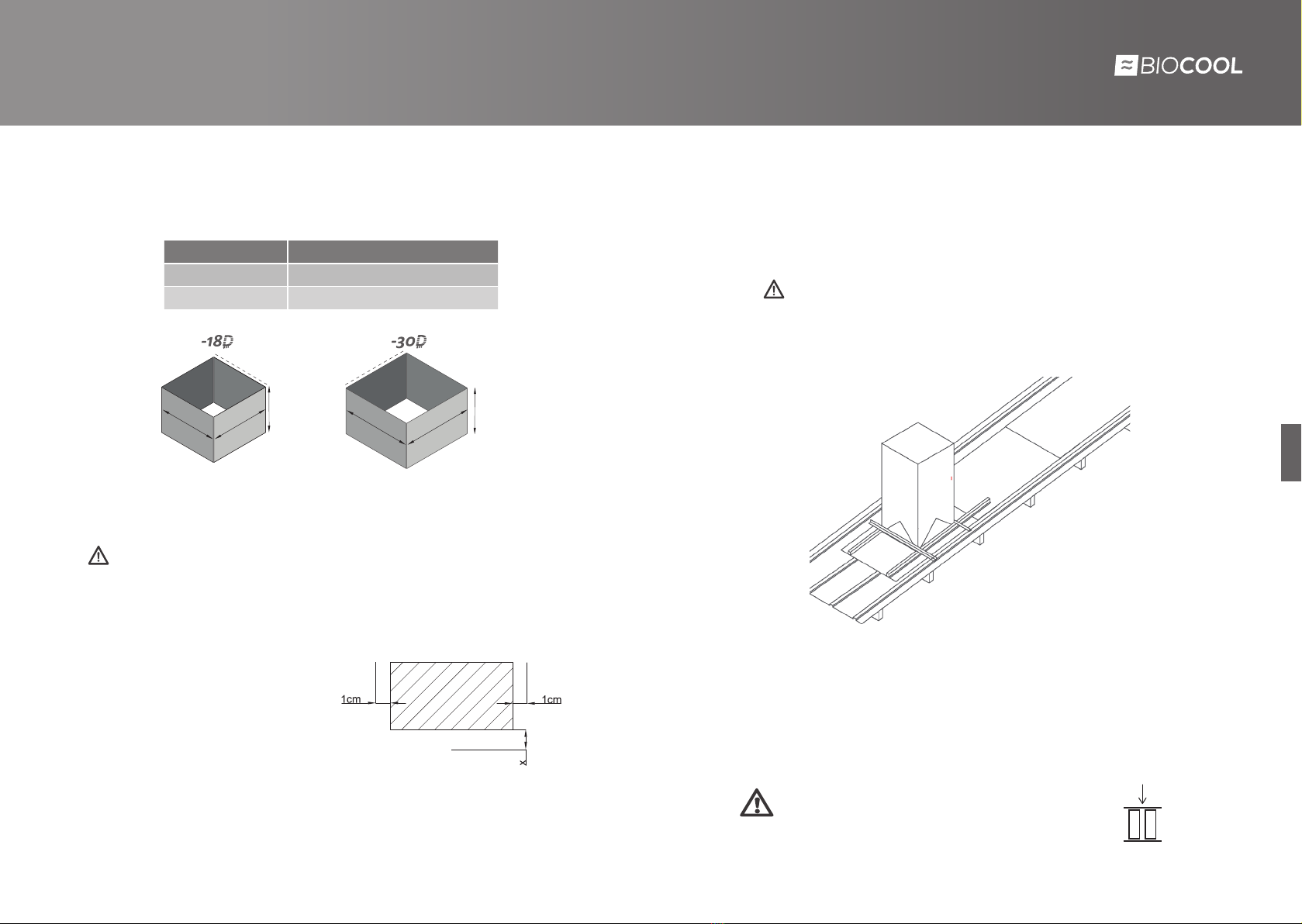
MODEL DUCTS DIMENSIONS
BIO-18D 660x660 mm. / 0,6-0,8 mm. espesor
BIO-30D 770x770 mm. / 0,6-0,8 mm. espesor
INSTALLATION
Ducts installation
Gap Cover Opening
ATTENTION! Before making a cut in the cover make sure that the weather
conditions are good and in no case with rain. On the other hand you must check
for the installation time required and sealing. NEVER LEAVE A OPENING IN THE
COVER, ITMAY CAUSE DAMAGETOTHE CLIENT.
Make the drill on the cover as shown in
the image. with the indicated margins.
The value of x is dependent on the type
of cover and its slope. The minimum
value recommended for “x” is 2 cm.
BIO
BIO
660
660
770
770
min. 300 mm
sobre cubierta
min. 300 mm
sobre cubierta
INSTALLATION
Remember:
• Minimumdistanceof cross-metalsheetbeding ofcm to maintainthesafety
margin of cm above the cover.
• For proper installation must be level.
• Sealing: With these sealing we will prevent the possible leakage of water into
the interior of the zone to climate
Once the duct sealed, you must use a li as a creane boom or any tool the rules of
evaporative liing to the cover.
The evaporative must be properly insured for their transport to the cover or in the
installation area.
You willneedan operatorin thecover abletodisengage andrelocatethe equipment.
You must ensure that the equipment is level for a
maxium performance and screw the evaporative.

ECO Cooling SoluonsINSTALLATION GUIDE
ENG
16
>17
>
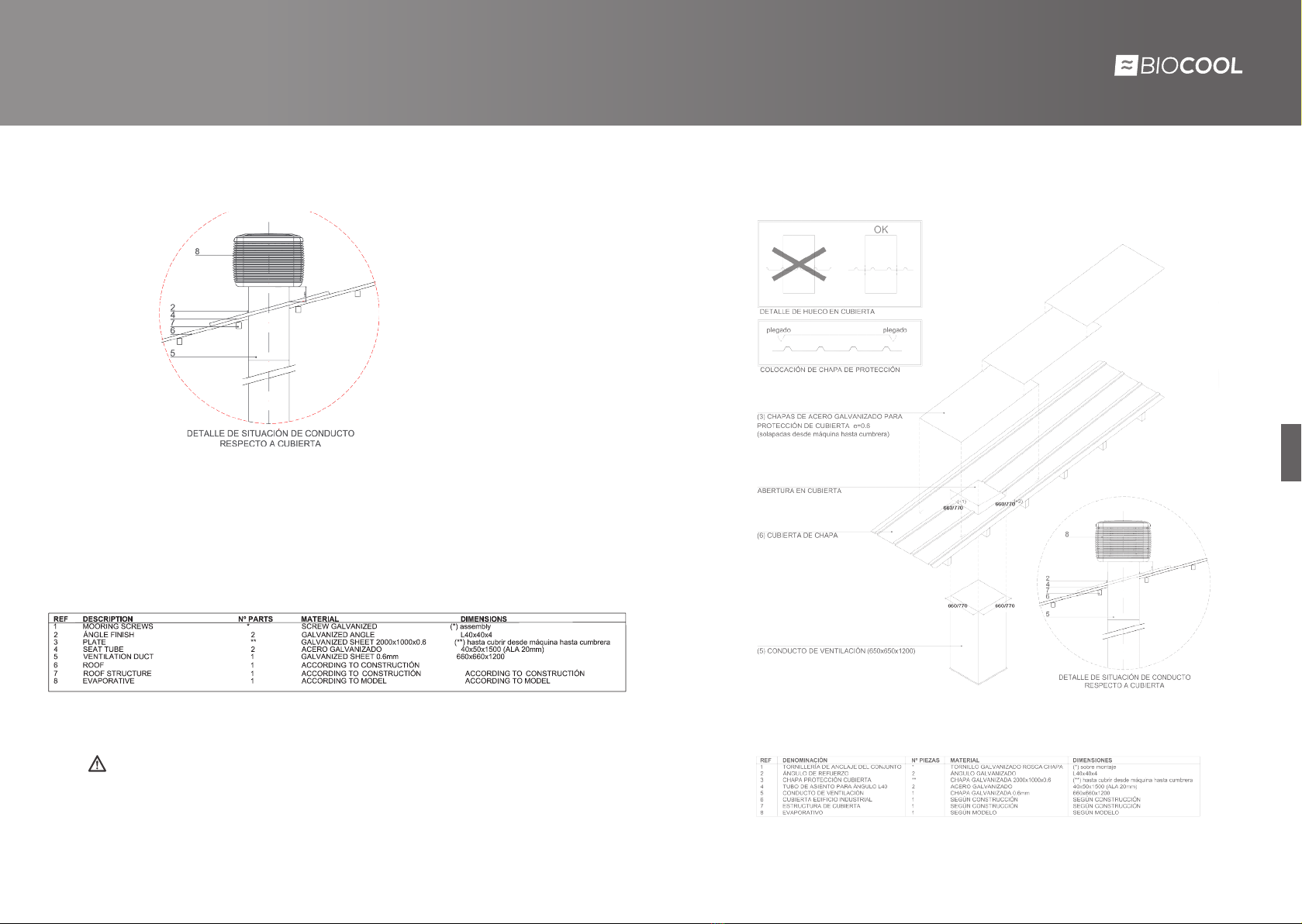
Example Installation type roof
(6) CUBIERTA DE CHAPA
ABERTURA EN CUBIERTA
(5) CONDUCTO DE VENTILACIÓN (650x650x1200)
(3) CHAPAS ACERO GALVANIZADO PROTECCIÓN DE CUBIERTA e=0.6
(solapadas desde máquina hasta cumbrera)
(4) TUBO DE ASIENTO PARA ÁNGULO L40x4 (40x50x2000;ala 20mm)
(2) ÁNGULO DE REFUERZO (L40x40x4)
PLEGADO DE CHAPAS (90º)
a b
a b
a b
Modelo A B
BIO 18 660 660
BIO 30 770 770
ÁNGULO DE REFUERZO (L40x40x4)
ÁNGULO DE REFUERZO (L40x40x4)
2 TUBOS DE ACERO 40X50X2000
ESTRUCTURA DE CUBIERTA
CUBIERTA DE CHAPA DE ACERO
CONDUCTO (660x660x1200)
660 a 550
CONDUCTO (550x550x1500)
550x500 45 ºC
DIFUSOR 2 CARAS
Example Installation type roof - Example BIO 18
ECO Cooling SoluonsINSTALLATION GUIDE
ENG
18
>19
>
Depending on the weather and the remaining time on the day of installation, it will
proceed to perform another installation of other evaporative unit or to perform
interior equipment assembly.
WARNING!
Never leave any area of open cover with a non complete installation.
Example Installation type roof Example Deck installation

ECO Cooling SoluonsINSTALLATION GUIDE
ENG
20
>21
>
1150 - 1250
950 - 1310
DISTANCIA MÍNIMA
INSTALLATION EXAMPLE
Example Installation type roof
SOPORTE
PERNOS DE SUJECCIÓN
MURO
1150 - 1250
950 - 1310
PERNOS DE SUJECCIÓN
DISTANCIA MÍNIMA
Generic frontage Installation example
INSTALLATION EXAMPLE
BIO BIO
1150 - 1250
950 - 1310
SOPORTE
CODO 90º
PERNOS DE SUJECCIÓN
MURO
DISTANCIA MÍNIMA
Generic frontage Installation example
CUBIERTA IMPERMEABLE
1150 - 1250
950 - 1310
BIO
BIO
Example Installation type roof

ECO Cooling SoluonsINSTALLATION GUIDE
ENG
22
>23
>
Internals Evaporative Assembly
1. First disengage the 3 side panel
clips
2. Hold the panel with both hands
and pull towards you.
3. Repeat with each of the panels.
Electrovalve
The electrovalve assembly will be on the inside of IP65
protection box, to protect from low temperatures and
prevent damage from freezing.
Electrovalve Connections
1/2 “
´
´
´
*
*
Llave de paso para cada máquina
Llave vaciado
Llave de paso principalLlave de suministro mínima
Entrada a 1/2”
* Electroválvula de
voltaje pulgadas
24 V
220 V
3/4“ - 3/4 ”
1/2“ - 1/2 ”
INTERNAL CONNECTIONS
Therewillbe aninstallationofakeystep foreachevaporativeunitandinaddition
to a key principal step for all the untis installed. You also install an emptying key to
the season closure.
SEE EXAMPLETYPE SCHEME ANNEX
Drain Valve
Water drained from the drain valve must be carried to the point of appropriate
download in the building or building installation, according to the regulations. It is
recommended that you do not drain the water never directly to the cover.
The drain valve comes from within the evaporative, you will have to put in its
corresponding zone and thread with the cap thread the projecting part of the lower
tank to ensure its stability.
The electrovalve prevents the entry of water when the drainage is open or the
machine is idle.
Once threaded drainage, ensure you drained by gluing a diameter PVC tube 32 mm
and length 1 meter.
Take this tube to the water discharge area or rain cover.
Model mm CAP to 32 mm
BIO 18 48 mm YES
BIO 30 32 mm NO
FOR BIO AND BIO DCVDC
Install the solenoid valve cap in the correct direction according to the position of
the cables, other type of installation can damage the solenoid valve.
Water supply
Water input Water output
Electronic
power supply
#1
#2
N
MODELS voltage inches
BIO18 axial 24 V 3/4 ” -
3/4 ”
BIO 30
BIO18 centrifugal 220 V 1/2 ” - 1/2 ”
*Solenoid valve of

ECO Cooling SoluonsINSTALLATION GUIDE
ENG
24
>25
>
ELECTRONIC CONNECTION
The control connection
Standard wall control connection
Maxium distance of m supply
Protect the control wire on the cover with a
corrugated cable to prevent damageo.
Biocool Control
BIO AXIAL
Biocool Control
BIO CENTRIFUGAL FAN
ELECTRONIC CONNECTION
The control connection
BIOCOOL MODEL BIO VARIABLE SPEED
Biocool Control

ECO Cooling SoluonsINSTALLATION GUIDE
ENG
26
>27
>
Control placement
Place the control in the area specified by the
client.
It is recommended that you place the control
at a minimum distance of the evaporative
connected,and ensure good communication.
Ifthedistanceis >m, will haveto be to crimp the
wire by adding a shielded x mm2 cross-section
wire cable and its corresponding RJ.
1. Connect the power and water supply and turn on the evaporative
from the remote control.
2. Turn on the evaporative from the remote control.
3. Check the exterior of the evaporative if there is any equipment with
loss of water or malfunction.
Any element not well connected to the electric panel will be reflected in the control.
The electric panel has a green LED which informs that it has power.
START-UP
Before to starting up all equipment follow the instructions in order for safety:
Safety box
Inside the equipment, in the accessory box is the electrical safety box. It is a three-
poles 20 A box with protection IP65.
1. Connect the power supply of the equipment to the input of the safety box. (three- phase for
BIO30 and single-phase for BIO18).
2.Connect output power wiring to the general low-voltage switchboard marked by the
customer.
3. Place the magnetic disconnect box in the duct as shown on the back picture.
- Safety box location -
Place here
Safety box General electric
table
Biocool Electronic
BIO x mm2
BIO x mm2
BIO x, mm2
BIO x, mm2
INTERIOR VIEW BIO18
INTERIOR VIEW BIO30
Safety box
Mechanical extractor connection
Consult the different options with BIOCOOL’s technical department.
General electric
table
Biocool electronic T’
N
F
T’
N
F
General electric
table
Biocool electronic
N -Neutral
T’ - Ground
R
S
T
N
T’
N
T’
R
S
T

ECO Cooling SoluonsINSTALLATION GUIDE
ENG
28
>29
>
Water scheme example
Considerations to take into account in the installation of plumbing:
• Place a shut-off valve to all machines.
• Place a draining shut-off valve to prevent accumulation of water in winter and
freezing problems.
• Makeuseofashut-offvalveforeachinstalledunitandbe able to cut the supply
in specific equipment.
• Use polyethylene pipe diameter corresponding to water supply connections.
• Entry to the evaporative will be /” and the electrovalve located before the
evaporative will be a /” female input and output.
• Check if the supply pressure is the necessary for supplying the full installation.
• Checking the plumbing connection of the entire installation to avoid losses and
leaks that can cause damage.
CONNECTION DIAGRAMS
MODELO WIRING TYPE
BIO-D wires of , mm2 section ( A)
BIO-D Three-phase cable(N+3F+Ground)
Connection diagram example

ECO Cooling SoluonsINSTALLATION GUIDE
ENG
30
>31
>
EachelectronicpanelhasaLEDsystemthatindicatesthemachineissupplied
with power.
The general panel must contain thermomagnetic switches with the expected
In=1,25xImax referred in the UNE .
Connection to the electric board WATER AND POWER SUPPLY
1. The water must always be clean, and the pressure must be between . to .
Mpa (. kgf/cm2)
2. There should be a valve (DN) near the entrance of the water inlet and a
cleaning duct.
3. Do not use untreated well-water, or low pH osmotic water
4. Ensure that the single phase voltage is / / / //±V, three-phase
voltage is ± V.
Water quality
Water type:
• The water supply for the equipment must be clean and from the mains,
guaranteeing a minimum water pressure at the entrance of each equipment.
• Do not use well water because of the high dissolved substances it may contain
(bicarbonates, carbonates, calcium ion, magnesium ion, boron, potassium ion
which tends to form clays...). If this is not possible, the water must be treated
according to the European Directive //CE.
• The temperature of the incoming water must be less than 45 degrees.
• The ph range should be between 6-9.
Hardness:
In very hard waters, a descaler will improve the performance of the equipment by
avoiding lime incrustations.
The water must have a hardness of ºhF, free of boron, salts,
carbonates, bicarbonates and other impurities.
In case the water hardness is considered hard or very hard, the automatic self-
cleaning of the equipment must be programmed at 4 h.
To carry out the electrical installation, the following considerations should be
taken into account:
• First make sure you have made a good connection to the safety box (located
at the boom of the machine as indicated above).
• An electrical sub panel must be made in each installation for the evaporative
unit system.
• Use the electrical wiring in the table above for all installations.
• It is recommended to connect each evaporative unit to each circuit breaker,
complying with current regulations. Each line is sized with the Imáx(A)
according to UNE 20460-5-523:2004
Recommendations for electrical and communication wiring.
Electrical connection
It is recommended to use this type of wiring according to the equipment installed.
This wiring must be on suitable conduit according to local regulations in force and
covered on a tray or cover. Otherwise, RZI-K halogen-free hose should be installed.
MODBUS communication connection
In Smart City Cooler installations with Modbus communication, shielded and
twisted communication cable of the BELDEN brand must be used.
ThiscablehasashieldedwirewhichmustbeconnectedtotheRS485communication
GND, never connected to the electrical earth.
MODEL TYPE OF ELECTRIC CABLE
BIO-18D 3 x2,5 mm2 section
BIO-30D Three-phase cable (N+3F+Earth)
The electrical wiring should NEVER go on the same tray/lid as the
communication one, in any type of BIOCOOL installation.

ECO Cooling SoluonsINSTALLATION GUIDE
ENG
32
>33
>
CHECK BEFORE
USE
1. The machine is leveled
2. Drain pipe is installed .
3. No Water dripping in operation.
4. Water level is normal.
5. The evaporative is well connected to the power.
6. Control lines are well fixed
7. Check nothing obstructs the tank or the fan
8. Check voltage and the current are normal.
9. Check the machine is operating under the required power
level
MANTEINANCE
10. To achieve maximum efficiency, cooling pads should be clea-
ned continuously. Do not use water pressure or hot water
more than 40 ° C. Clean with a so brush.
11. To avoid freezing in winter, you should empty the tank and
cut water. In case of snow or dust cover it when not using.
CLEANING This series has its own cleaning system. We recommend using
the cleaning function at least once a month
DUCT DESIGN
1. Duct material must be of galvanized metal sheet, steel, plastic, aluminum, etc.
2. The grilles or diffusers should be installed where refrigeration is necessary.
Grilles characteristics will be determined depending on the speed of the air.
The material could be aluminum, wood etc. Doubled air deflection grilles
m/s,flow rate of the air, are recommended.
3. The duct must be designed to 6-8 m/s speed air in the main duct, 4-5 m/s in
the pipes, and m/s at the end.
4. It is advisable an economical duct design, without excessively noise.To
reduce resistance, the duct curvature radius should not be less than 1.5 times
of its width.
5. Ductwork should not exceed metres in length.
6. It is advisable that the layout of the duct is straight, no curves or angles, to
prevent resistance.
7. According to the different air flows, duct should be designed with different
sections; the longer the duct is the minor the section must be .
8. If there are ramifications, these should be set to adjust the air flow.
OPENING AND SEASON CLOSURE
SERVICE SCOPE MAINTENANCE
You must ensure a technical assistance in the case as required at any time of the
season, including labour for solving any kind of fault. Does not include the price
of the rest of the component need to be replaced (unless they are covered by
warranty).
The tasks to be performed in teams evaporative should be divided in two ways:
Technical maintenance.
These equipments require technical routine maintenance , if not done, can cause
inefficient operation or even not working.
Tasks carried out follow the indications of the manufacturer for both opening and
closure. So:
1.In spring and summer we check equipment function is acting properly aer
a prolonged stop proceeding to a cleaning work and in the event of failure or
malfunction detection informs the client to proceed with their replacement.
2. in autumn the status of the equipment is reviewed reporting detected anomalies
to solve them before the start of the following season
Hygienic Maintenance.
Although opening tasks perform a cleaning of the evaporative, they are subject to
a national regulations for the control and the prevention of legionella (still being
a classified equipment with less probability of proliferation and dispersal of the
Legionella). Therefore, they should perform an annual cleaning and disinfection
(to start) and subsequently a water analysis for the detection of Legionella (aer
between and days aer treatment) in accordance with the R. D. /.
Companies authorized to carry out this type of services to third parties are those
listed in the Register Official of Establishments and services Biocides ROESB.

ECO Cooling SoluonsINSTALLATION GUIDE
ENG
34
>35
>
Aer each of the maintenance operations, a technical report on the condition of
the equipment is prepared so they may have a greater control of their installations.
This report would be aached to the Record Book of the installation for the control
of Legionnaire’s disease along with the certificate of cleaning and disinfection and
analytical results to comply with the regulations in force.
Point out that equipment have an automatic cleaning of tray and drain system .This
system will allow also leave the tray without water when the appliance is unused
during a season, reducing most if possible, the risk of proliferation of Legionnaire’s
disease to empty the tray both when the equipment is not used as when it reaches
high values of suspended solids.
Review the following points :
REVIEWPOINTS:
• Draining and cleaning tray and equipment.
• Water pump.
• Automatic gate closure.
• External panels (housing evaporative panels)
• Evaporative cellulose filters.
• Review irrigation water (water dispenser)
• Eye examination of electrical lines, water and sanitation.
• Motor fan.
• Water detector.
• Solenoid electrovalve.
• Automatic drain w.
• Automatic filling.
OPENING AND SEASON CLOSURE
SEASON OPENING WORKS:
• Disconnect the power supply.
• Remove the filter panels to give access to the interior.
• Wash the filters to remove the dust accumulated during the winter. Change
filters if they are in bad condition.
• Turn on the electricity switch inside of the air conditioner.
• Connect the water supply and electrical supply.
• Put the filters panels to close the unit.
• Start-up of the air conditioner.
OPENING AND SEASON CLOSURE
SEASON CLOSURE WORKS
• Disconnect the power supply.
• Close the water supply.
• Remove the filter panels to give access to the interior.
• Disconnect the power switch inside of the air conditioner.
• Check and clean the guers of water from the tap.
• Allow water to drain from the tank through the drain valve that is automatic.
• Aer draining all the tank, clean the tank and the pump filter.
• Put the filter panels to close the unit

PROBLEM COMMON CAUSES POSSIBLE SOLUTION
The evaporative cooler doesn’t work
and the buons do not respond
External switch (machine base) or interior switch off, power failure,
bad connection, blown fuse, loss of connection between the control
box and the machine, faulty remote controls..
Check that the switches are on, measure the voltage, and connect properly, reset or replace it, check connections,
replace the control panel. If it happens again, you should check again if there has been an overload.
No airflow Warming up the engine, loss of electrical connections, damaged
contact, pre-cooling mode on, faulty remote controls .
If overheating engine will start aer 20 m. If the connection failures, check all electrical connections, if the contact
isbroken,replace it,if pre-cooling functionis ON,turn offthis functiontemporarily,if the remotecontrol isdefective
must be replaced, if the engine is damaged must be changed. Check the parameters of voltage and current.
Pump is working but doesn’t cool well. The cooling pads are dirty, insufficient air supply, dry pads or lack of
water, excessive moisture in the atmosphere..
If the problem are the pads, clean or replace, install grilles for the air in the places that need cooling, if the pads are
dry, check water distribution and the tank for possible obstruction, if there is excessive humidity in the atmosphere,
the evaporative doesn’t work at 100% because it works beer with drier climate. If desired, turn off cooling mode
in such days and turn on fan only..
Pump fails Broken water pump, loss of electrical connection, water level sensor
is broken or damaged, faulty remote controls.
If the pump is broken must be replaced, failed connection, if there is no water check valves and tank, if your remote
control is defective must be replaced.
Pump is working but no water flows Water pumpisblocked, watervalveislocked,watersupplierislocked. If there is a pump blockage should be cleaned, if there is a valve blockage clean it, if the water supplier is locked
clean it..
Cleaning mode is activated too many
times or too much water flows.
Self-cleaning function is activated, faulty valve, the drain valve is
leaking, faulty remote controls.
If the self-cleaning function is enabled, temporarily disable, if the valve is obstructed or faulty, cleaning or changing,
if the drain valve leaks, check or replace the valve, if the remote control does not work, replace it.
Water drips on the inside The pads are broken or blocked, excessive amount of water in the
pads.
If the pads are dirty or damaged, clean or replace, if there is excess water probably the water distributor is
unbalanced, balance it.
Smells The evaporative is with dirt. Clean the evaporative cooler completely
White residue High levels of salt in water. Drain water more frequently.
Red flashing on the remote control.
Erro de comunicação
Check the instructions in the BIOCOOL Control manual.
Erro de preenchimento
Erro de esvaziamento
Erro de motor
The communication green LED on the
electronics does not light up
Short-circuit in the communication cable, damage to the electrical
system and lack of power supply.
Change communication cable, check power supply or replace electronics.
PROBLEMS AND SOLUTIONS ECO Cooling Soluons
36
>37
>

ECO Cooling SoluonsINSTALLATION GUIDE
ENG
38
>39
>
Q&A-Installation
BIOCOOL ESTANDARD COOLERS
Communication errors in installation
• Why did not detect some coolers?
1. Reviewlocationof connectionofBioCool Standardcontrol andconnected
coolers
2. Make sure you have good contact with the RJ wiring -electronic tab HUBB
3. By using the crimper : CAUTION! Because if we press a lot you can join
wiring and lose communication .
4. Makeuseofanaccessory such as a flange forpressure connection RJ with
electronic tab HUBB ensuring a good connection.
5. To ensure it is resolved and there is good communication, see BioCool
control in the solid line in the right corner that it is fixed.Otherwise,
change the HUBB.
Electric installation errors
• What is the wiring recomended in the power supply of the cooler?
The electrical wiring must be protected on electric tray.In other case can be
installed follow the UNE 21123 UNE designation W - K 0.6 / 1 kW with flexible
conductor.
NEVER! Place the communication cable and power supply in the same tray
MODELO TIPO DE CABLE ELECTRICO
BIO-18D 3 x2,5 mm2 de sección(Imax=10 A)
BIO-30D Cable trifasico (N+3F+Tierra)
Q&A-Installation
• Should I put some kind of protection??
In the case BIOCOOL coolers , it is recommended to place each evaporative
coolerto acircuitbreakerboxdistribution boardor generalstress.Onegeneral
low-tension should have the MCB’s with In> =1,25 x Iprevista contemplated by
the UNE 20460-4-43.
Water installation
• What PH should I use?
PH between -.
• What water main should I use to pipe water supply ?
We recommend using pipe polietilieno to hold well pressure ( 8-10 kg / cm2).
NEVER use a drainage pipe as it cannot withstand sufficient pressure
• Can I make the water supply from a tank ? And the water treatment?
Yes, if the supply is made from a tank , it is recommended that the pressure at
the end of the line installation is 1.5-3 kg / cm2 .. In addition , you must perform
maintenance on the valves cleaning the grids of these for cases with water
with gravel.
• ¿How many valves should be placed?
Se recomienda una llave de paso de cada equipo y luego una general, además
de una llave de paso para desagüe. See previous scheme.
This manual suits for next models
8
Table of contents


