BioCut SterilCut C5 User manual
WI-095 SterilCut C5 User Manual Revision 4 1
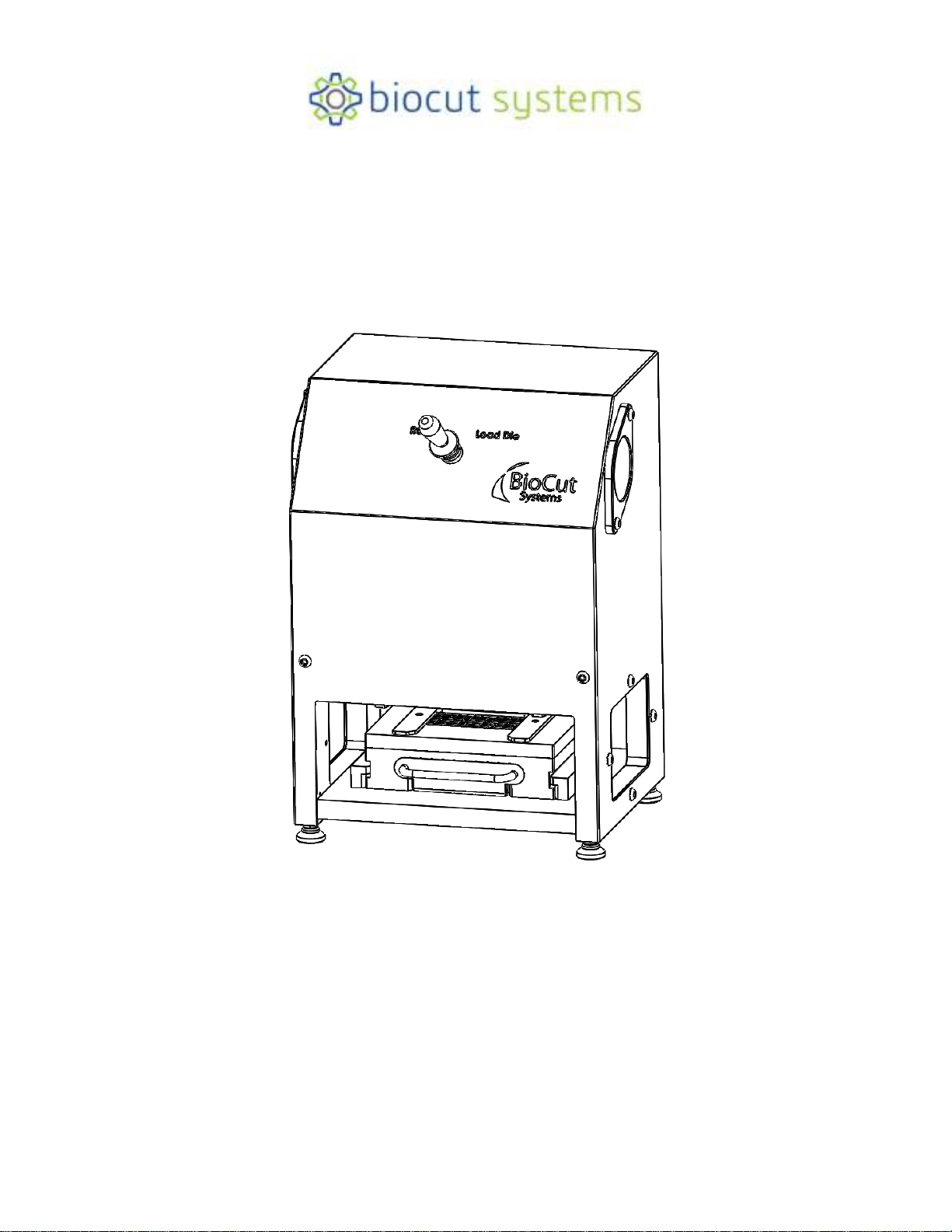
SterilCut C5 User Manual
© 2019, BioCut, LLC
Biocut, LLC
8219 W. Bradley Road
Milwaukee, Wisconsin 53223
Phone: 262-946-1052
Fax: 262-946-1056
www.biocutsystems.com

WI-095 SterilCut C5 User Manual Revision 4 1
Copyright 2019 ©, Biocut, LLC. All rights Reserved. No part of this document may be
reproduced or transmitted in any form or by any means including electronic, photocopying,
mechanical, or otherwise. This document may not be translated into other languages
without BioCut’s express written approval. The Contents of this Document are strictly
confidential and are subject to amendment or revision without notice.
BioCut, LLC
8219 W. Bradley Road
Milwaukee, Wisconsin 53223
Phone: 262-946-1052
Fax: 262-946-1056
www.biocutsystems.com

WI-095 SterilCut C5 User Manual Revision 4 2
Liability Disclaimer
3
Warranty Statement
3
Safety Symbols
4
Recommendations
4
Safety Precautions
4
Applications and Uses
5
Component Identification
6
Site Preparations
8
Supply Air
8
Unpacking and Staging
9
Installing Die 1
0
Cutting Operation 1
3
Daily Cleaning 1
4
Decommissioning 1
4
Routine Maintenance 1
5
Troubleshooting 1
5
Replacement Parts 1
5
Product Specifications 1
6
Table of Contents

WI-095 SterilCut C5 User Manual Revision 4 3
THIS MANUAL CONTAINS THE INSTRUCTIONS NECESSARY TO OPERATE THE STERILCUT C5 SAFELY
AND IN ACCORDANCE WITH ITS FUNCTION AND INTENDED USE. TO AVOID POTENTIAL SERIOUS INJURY
TO THE USER AND/OR DAMAGE TO THIS DEVICE, THE USER MUST READ THIS OPERATING MANUAL
THOROUGHLY AND BE FAMILIAR WITH ITS CONTENTS PRIOR TO USING THIS EQUIPMENT. THE
ILLUSTRATIONS IN THIS MANUAL ARE FOR EXAMPLE PURPOSES AND MAY NOT REFLECT THE EXACT
SETUP OF YOUR PRODUCT.
LIABILITY DISCLAIMER
Purchaser assumes all liability for unsafe operation of the SterilCut C5 Press. Misuse of this machine may result in
damage to the machine or cause injury or death to the operator. BioCut is not liable for death, injuries to persons or
property, or incidental, consequential, contingent or special damages arising from the use of the Product.
Warranty Statement
The Warranty for the SterilCut C5 Press is provided in the Master Agreement Terms and Conditions and nothing in
this document alters the stated warranty. THERE ARE NO IMPLIED WARRANTIES OF MERCHANTABILITY AND
FITNESS FOR A PARTICULAR PURPOSE, TO THE EXTENT APPLICABLE, SHALL BE LIMITED IN DURATION
TO THE APPLICABLE PERIOD OF WARRANTY SET FORTH ON THIS PAGE. THE PURCHASER’S ONLY
REMEDIES IN CONNECTION WITH THE BREACH OR PERFORMANCE OF ANY WARRANTY ON BIOCUT ARE
THOSE SET FORTH IN THE MASTER AGREEMENT. IN NO EVENT WILL BIOCUT OR ANY COMPANY
AFFILIATED WITH BIOCUT BE LIABLE FOR INCIDENTAL OR CONSEQUENTIAL DAMAGES
Please note that maintenance and cleaning of this product must be carried out by a trained and qualified individual.
The failure to do so will void the Product warranty.
WI-095 SterilCut C5 User Manual Revision 4 4
Safety Symbols
PROHIBITED: This symbol indicates an action that is strictly prohibited. The
prohibited action should never be carried out, under any circumstances.
CAUTION: This symbol indicates a warning or precaution related to safety.
Please read and understand the text and use the equipment safely.
ACTION: This symbol indicates instruction that requires an action. Please follow
the instructions carefully.
IMPORTANT: Please review the following instructions.
Warnings&Recommendations
PROHIBITED: Never place any body part inside the Press cabinet while the unit
has pneumatic (air) pressure being supplied. Doing so may result in injury or
death.
PROHIBITED: Never supply more than 100 psi (.690 MPa) air pressure into the
Press. Doing so may result in injury or death, and may damage the Press.
PROHIBITED: Never attempt to operate the Press if any part of the pneumatic
(air) system has been damaged.
PROHIBITED: Only one trained technician may operate the Press at a time. All
other personnel must be at least 10 feet (3 meters) away from the Press during
operation.
SafetyPrecautions
CAUTION: Read all instructions before uncrating, commissioning and operating
the SterilCut C5 Press.
CAUTION: Wear ANSI or CE approved safety glasses while operating the Press.
WI-095 SterilCut C5 User Manual Revision 4 5
The SterilCut C5 Press has been designed with the Medical Industry in mind. From its Stainless
Steel exterior to its fully wash-down proof build, this Press has been designed to be used in a
clean room environment where avoiding any form of contamination is critical.
Pneumatic operation eliminates the need for supplied electrical power.
Simple and safe to use. The two pneumatic activation buttons located on either side of the Press require
two-hand operation with anti-tie-down safety measures.
Applications & Uses
The SterilCut C5 Press is designed to work with BioCut brand medical/bioscience
cancellous die sets to cut cancellous bone into cube shapes from a precut disk.
Introduction
WI-095 SterilCut C5 User Manual Revision 4 6
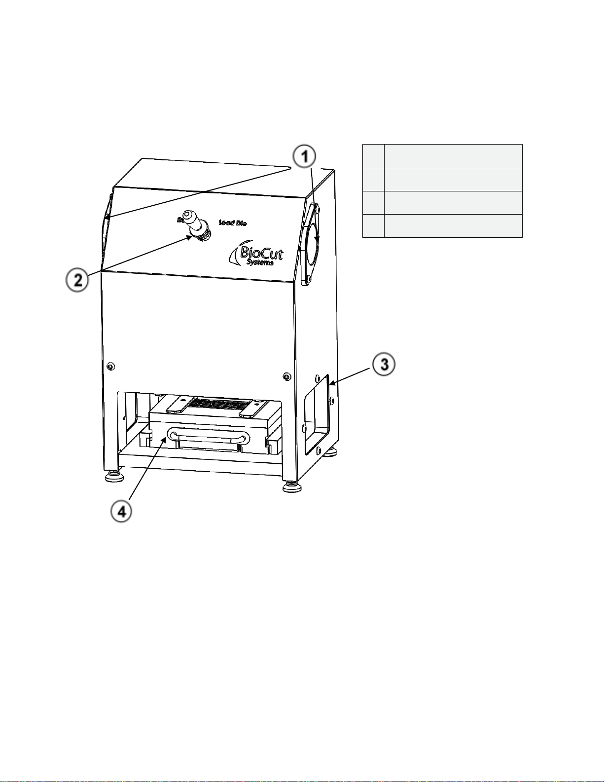
Press Component Identification
1
Pneumatic Actuation Buttons
2
Setup Switch
3
Access Windows
4
Die Set
WI-095 SterilCut C5 User Manual Revision 4 7
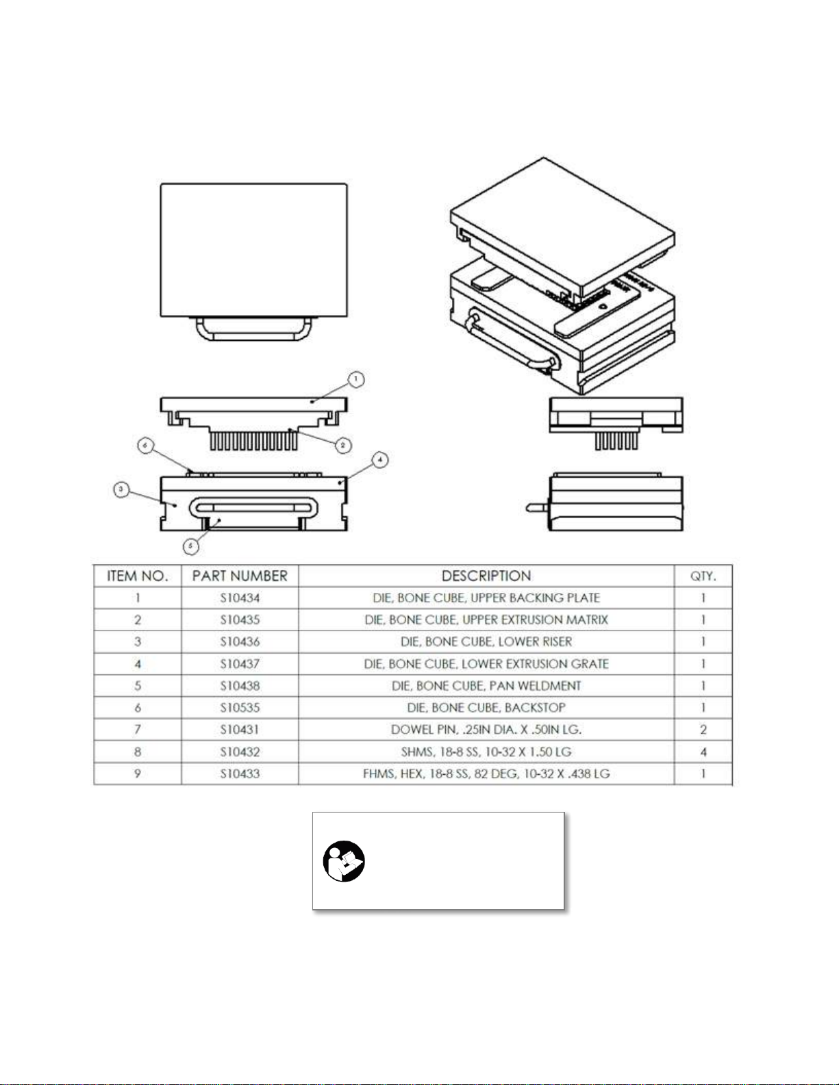
Die Set and Accessories Identification
IMPORTANT: The Die Set
shown is for illustration
only. Your specific Die Set
may differ from the one
shown

WI-095 SterilCut C5 User Manual Revision 4 8
Site Preparations
Consideration should be given to the location where the Press is to be installed. Avoid uneven or
unstable locations as well as high traffic areas. Provide enough space around the Press to allow
sufficient access for maintenance and repair.
Supply Air
The SterilCut C5 Press requires a Supply Air (Instrument Air) pressure of 90-100 psi (.620-.690 MPa) and
a recommended operating volume of at least 10 cfm (280 l/min).
NOTE: If a dedicated compressor is being used, the tank should have a 30-gallon (115 liters) volume minimum for
uninterrupted operation.
Install a shut-off valve (not included) between the supply air and the Filter/Regulator/Lubricator and
Press. Mount the shut-off valve near the Press where it is easily accessible for maintenance or
emergency.
Supply Air should be filtered, regulated and lubricated for the Press to operate correctly. A
Filter/Regulator/Lubricator is included with the SterilCut C5 Press. This device is capable of filtering air
to 5 microns, regulating the air pressure to the press at 90-100 psi (0.620-.690 MPa) and conditioning
the air for maximum cylinder life. Follow the Filter/Regulator/Lubricator Manufacturer’s Instructions
(www.smcusa.com) for installation, operation and maintenance of this device.
A push-to-connect type fitting and tubing is included to allow connection to the press.
Included Hardware
Item Manufacturer
Part No.
Photo
Item
Manufacturer
Part No.
Photo
Filter/Regulator/
Lubricator SMC
AC30-N02E-Z-B
3/8” OD Nalgene
LLDPE Tubing
Thermo
Scientific
8010-0250
Stainless Steel
Connector
SMC
KQG2H11-N02S
and
KQG2L11-N02S
Quick-Connect
Coupling
Specify type
when ordering
to match your
facility
ATTENTION Before moving or installing this press, those responsible must read the
Introduction and Installation sections of this manual.
IMPORTANT: The C5 press is vented internally. It is important that the air delivered into the
press is clean enough for release into the Clean Room. If it is not, please contact BioCut to
discuss options to vent press exhaust air out of the Clean Room.
Installation
WI-095 SterilCut C5 User Manual Revision 4 9
NOTICE: A complete IQ-OQ checklist is available for use or reference (F-123 SterilCut C5 IQ-OQ
Checklist).
Unpacking&Staging
Before unpacking, examine the packing case carefully for any signs of damage. If damage is detected, contact
the carrier. If the packing case is intact, remove the shipping enclosure.
Before transporting the Press to the installation site, remove the shipping enclosure. Leave all wrappings on the
polished metal cabinet until the Press is in the final position. This avoids scratches and damage to the external
facade.
Use an appropriate lifting device rated at a minimum of 150 lbs. capacity to lift the Press from the shipping
enclosure to the bench on which it will operate. The press can be lifted with two people capable of lifting 60 lbs
each. Once on the bench, remove the wrappings covering the stainless steel cabinet.
Utility Connection
Use the 3/8-inch diameter poly tube to connect the output of the Filter/ Regulator/Lubricator to the 3/8-inch
bulkhead Push-to-Connect port on the rear panel of the SterilCut C5 Press.
PROHIBITED: Never supply more than 100 psi (0.690 MPa) air pressure to the Press. Doing so
may result in injury or death, and may damage the Press.
CAUTION: Do not place any part of your body under the Press while it is elevated
Use extreme caution when doing any work to the bottom of the Press. Not only is the Press less
stable when being suspended, but any hydraulic failure could cause serious injury.
Bench or table must be rated for a minimum of 200 lbs (320 kg). If unsure, contact BioCut Systems,
Inc. about an optional Clean Room Ready Press Table.

WI-095 SterilCut C5 User Manual Revision 4 10
Installing Die
1. Use a clean BioCut Die Set.
2. Place the Setup Switch in “Load Die” setting. This will prepare the press for die instillation.
3. With the compressed air turned on, and the Setup Switch in “Load Die” setting, press and hold both Actuation
Buttons. The press will extend to its lowest position and remain there. When the press stops moving, release
the Actuation Buttons.
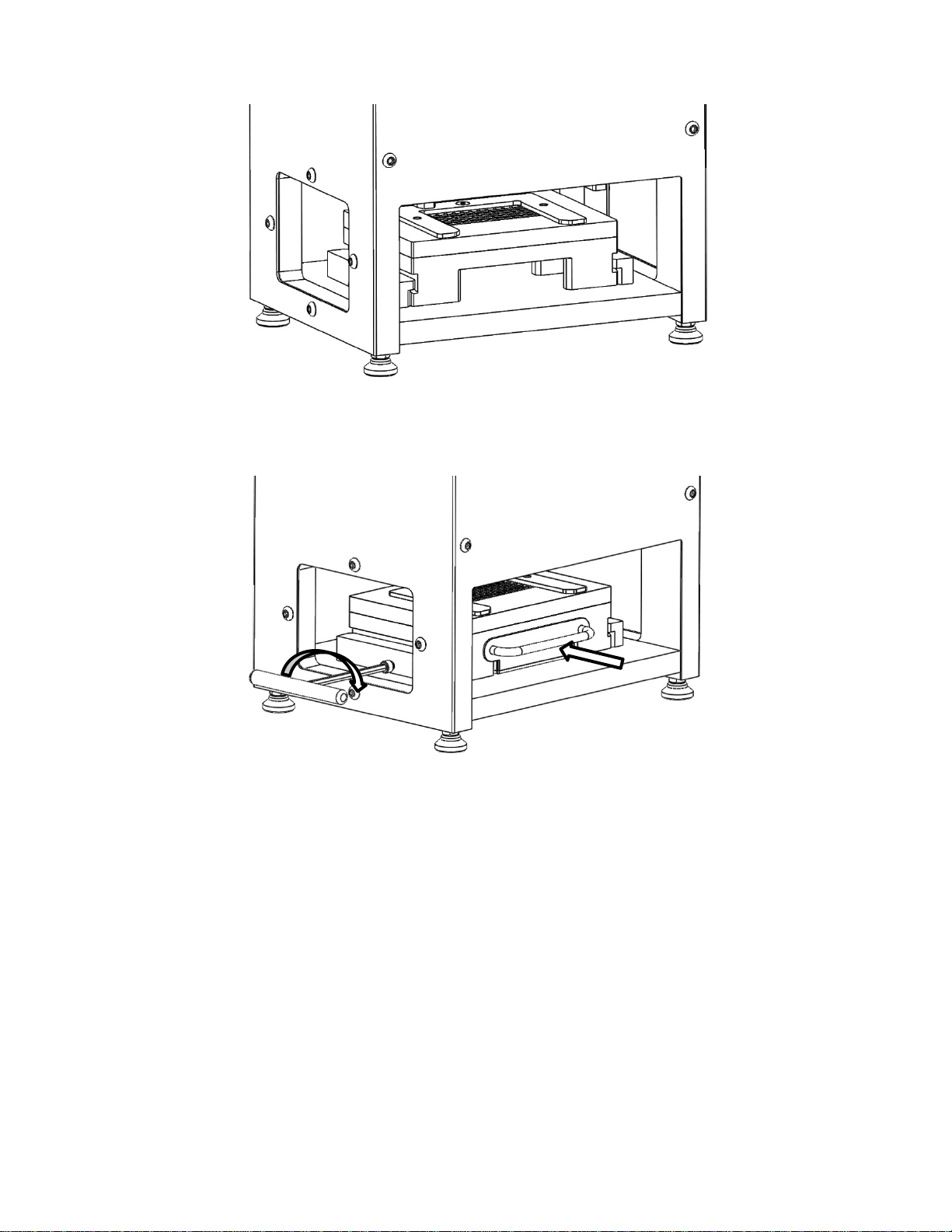
4. Slide the Upper Backing Plate between the rails until it reaches the pins located at the rear of the press and
stops.
WHEN AIR PRESSURE IS SUPPLIED, THE MAIN CYLINDERS WILL BE ENGAGED: Never
place any body part inside the Press cabinet while the unit has air pressure supplied. Doing so
may result in injury or death.
Operation
NOTICE: Both Actuation Buttons must be activated within 0.5 second of each other or the operation
will not start.

WI-095 SterilCut C5 User Manual Revision 4 11
5. Hold light pressure to keep the Upper Backing Plate against the pins, and lock the Upper Backing Plate in the
press using a 3/16” hex wrench. Remove the wrench when complete.
6. Place the Setup Switch in the “Run” position. This will retract the press and prepare it for operation.
7. Prepare the lower die half as shown below. Make sure Lower Riser is bolted to the Lower Extrusion Grate.
NOTE: Use of the Backstop is optional.
CAUTION: Remove hex wrench before proceeding to Step 6. The press will retract in the next
step which will trap the hex wrench if it is not removed.
WI-095 SterilCut C5 User Manual Revision 4 12
8. Slide the lower die half between the lower rails until it reaches the pins and stops.
9.Insert the Pan into the Lower Riser. Hold light pressure on the Pan to keep the lower die assembly against the
pins, and lock the lower die assembly in the press using a 3/16” hex wrench. Remove the wrench when
complete.

WI-095 SterilCut C5 User Manual Revision 4 13
Cutting Operation
1. Once Die Set is installed correctly, operation may begin.
2. Place the Setup Switch in “Run” mode
3. Place the material to be cut in the die opening using a manipulation device.
4. When ready to actuate, press and hold both Actuation Buttons until the cut is complete. The material will be
pressed through the die and collect in the Collection Tray. Release the Actuation Buttons to return to the up
position.
5. Carefully remove the Collection Tray to access the finished material. Replace the Collection Tray before
starting the next cycle.
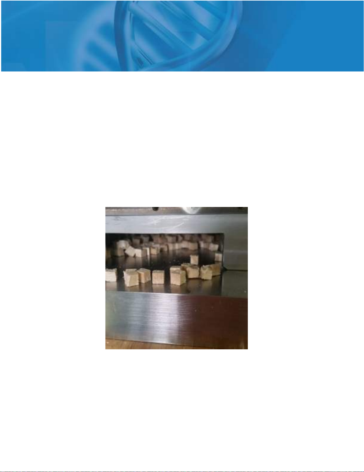
6. Every 2-3 cycles the Lower Extrusion Grate may need to be cleared of chips for smoother operation. Insert the
Upper Extrusion Matrix into the Upper Backing Plate as shown below. Be sure Extrusion Matrix is fully inserted.
Actuate the press to clear the cubed material in the Lower Extrusion Grate. Remove the Upper Extrusion Matrix
once complete.
7. Repeat Steps 3-6 as many times as is required, or until the material lot is complete.
WHEN AIR PRESSURE IS SUPPLIED, THE MAIN CYLINDERS WILL BE ENGAGED: Never
place any body part inside the Press cabinet while the unit has air pressure supplied. Doing so
may result in injury or death.
WI-095 SterilCut C5 User Manual Revision 4 14
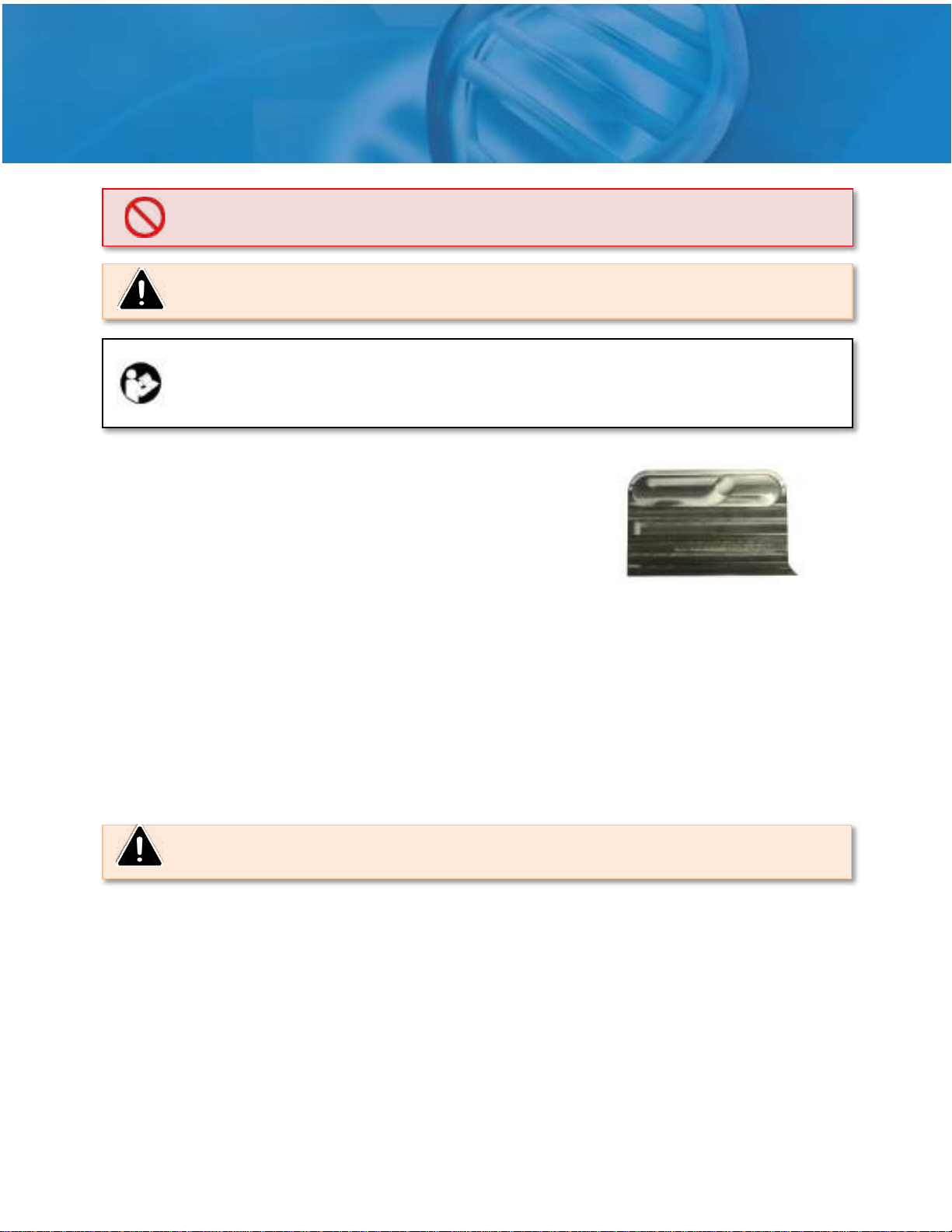
Cleaning
Remove the die set by reversing the instillation instructions.
The baffles and retainers around the Actuation Buttons may be
removed for cleaning and sterilization if company protocol requires.
The included cleaning tool many be used to clean the Upper
Extrusion Matrix of built up bone.
Inspect all gaps and areas between the press platens for debris.The Access Windows may be removed
to facilitate cleaning. Thoroughly clean the Press between and around the platens.
An alcohol solution is recommended to clean the platens of the press. Using slight pressure with a mild
abrasive sponge or towel, wipe down all areas where the material has come in contact. Attach this
sponge or towel to a rod when cleaning between the platens to avoid placing hands in the Press.
Rinse equipment with plenty of water. Ensure that any clinging material has been removed.
A Peracetic Acid (CH3CO3H) solution of between 0.2% and 1% is recommended as a sanitizer after
removing loose debris. This solution should be used generously over the entire Press to ensure
sanitization of all surfaces.
Decommissioning
Before moving or storing the Press the following steps are required:
1. Turn the air supply to the OFF position.
2. Disconnect the air pressure from the Filter/Regulator/ Lubricator.
Maintenance
PROHIBITED: Never place any body part between the upper and lower platens of the Press
while air or power is supplied. Use a tool to avoid reaching into Press opening.
CAUTION: Wear appropriate personal protection equipment prior to handling chemicals or
attempting to clean the Press.
NOTE: The Cleaning Recommendations are only to be used as a guideline from the
manufacturer. In no way should these recommendations be used as the sole cleaning
procedures for the Press within a clean room environment. Please devise and implement
cleaning procedures based on your company’s standards and cleaning protocols.
CAUTION: It is not recommended to spray sanitizing solution directly inside the Press.
Inadvertent spray is acceptable.
WI-095 SterilCut C5 User Manual Revision 4 15
3. Remove the supply air line from the push-to-connect ports on the back of the press.
Routine Maintenance
All SterilCut C5 Press pneumatic cylinders are pre-lubricated, however lubricated air is recommended for
maximum cylinder life. If the Press is installed without a Lubricator (see Installation section) contact
Biocut for manual lubrication instructions. Air leaks will indicate the end of the usable life of the
cylinders. If such leaks occur, contact Biocut for options on rebuilding or replacing cylinders.
Maintenance Task Maintenance Period
Clean Platens Daily, or as required by company policy
Drain Incoming Air Filter Review Daily; drain as needed
Replenish Air Lubricant Review Daily; fill as needed
Filter/Regulator/Lubricator
Water can accumulate within the filter and should be drained periodically. This is water that was removed
from the air prior to entering the Press system. Please refer to the manufacturer’s recommendations
regarding liquid removal. Replenish lubricant and inspect or replace the filter element per the
manufacturer’s recommendations.
Troubleshooting
Below are some common troubleshooting tips for the SterilCut C5 Press. If these do not resolve the
issue, please contact Biocut.
Problem Recommendations
The Press is stuck in the lower position Ensure the press is in the “Run” mode.
The Press will not cut fully through the
material.
Check for adequate pneumatic pressure. The Press should be
supplied with a minimum of 90 psi (0.620MPa) of filtered
compressed air or
Check your die for damage or wear. Purchase
a replacement die if necessary.
The Press will not activate even though
adequate pneumatic pressure has been
supplied
Ensure that the actuation buttons are pressed at the same
time (within 0.5 seconds of each other).
Replacement Parts
Kit, Intl Fittings & Tube, C5
P11023
Valve, ¼ NPT, Pilot Driven
H10463
Valve, Hand Lever, 2 Position
H10627
Two Hand Safety Circuit & Buttons
H10457
Baffle, C5
P11024
NOTICE: Do not store this Press in areas subject to high temperature or humidity changes
which may result in condensation. Do not store this Press in areas where it will be exposed to
water. For long term storage, the Press should be stored with a drying agent such as silica gel.

WI-095 SterilCut C5 User Manual Revision 4 16
Shipping
Packaging
Press secured to and enclosed in a wooden
crate
Crated Weight
150 lbs (68 kg) (approximate)
Transportation/Storage Temperature
32º - 120ºF (0° - 49°C)
Physical Specifications
Overall Dimensions 12in(31cm) Wide x 9in(23cm) Deep x
17in(43cm) Tall
Weight
110lbs (50kg) (approximate)
Materials of Construction (Outside of
Press)
300 Series Stainless Steel
Utility Requirements
Ambient Room Temperature
32º - 110ºF (0° - 43°C)
Supply Air Pressure
90-100 psi (0.620-0.690 MPa)
Flow Rate
5 cfm (140 l/min)
Conditioning
Filtered to 5 microns and lubricated
Performance
Throat Opening
2.875 in (73 mm)
Cutting Area
7 in (178 mm) wide x 7 in (178 mm) deep
Cut Stroke
1.125 in (28.6 mm)
Pneumatic Use 0.3 ft3/cycle (8.5 l/cycle) at 4-6 cycles/minute
(100 psi, 0.690 MPa maximum)
Cutting Force
4.4 Tons (8,800 lbF/39 kN) min
Safety Features
Actuation Switches
One pneumatic switch on both sides of the
Press provides a two hand, anti-tie-down safety
process
1. Will not actuate when either button is
pressed individually
2. Will not actuate when both buttons are
pressed more than 1 second apart
3.
Will not actuate when either button remains
pressed from a previous actuation
Optional Accessories
Clean Room Ready Press Table
Optional
Custom Infeed Table Optional
Product Specifications

Table of contents
Popular Industrial Equipment manuals by other brands


Air & Allied Sales
Air & Allied Sales TOKU T-6 Maintenance Instruction

schmersal
schmersal AZM400Z-ST2-I1-2P2P-T-E instructions

Arrowquip
Arrowquip Q-POWER 106 SERIES product manual

Ridart
Ridart 442S quick start guide

Danfoss
Danfoss IPS 8 Technical data, installation and use

Regulus
Regulus PS 400 K+ Installation and operation manual