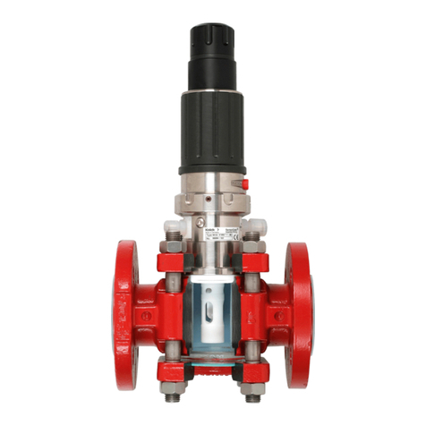
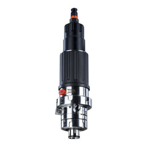
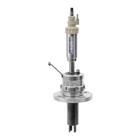
Knick WA111 User manual

User Manual WA111
Retractable Fitting
www.knick.de
Read before installation.
Keep for future use.

WA111
2
Supplemental Directives
READ AND SAVE THIS DOCUMENT FOR FUTURE REFERENCE. BEFORE ATTEMPTING TO ASSEMBLE, INSTALL,
OPERATE OR MAINTAIN THE PRODUCT, PLEASE ENSURE A COMPLETE UNDERSTANDING OF THE INSTRUC-
TIONS AND RISKS DESCRIBED HEREIN. ALWAYS OBSERVE ALL SAFETY INFORMATION. FAILURE TO COMPLY
WITH INSTRUCTIONS IN THIS DOCUMENT COULD RESULT IN SERIOUS INJURY AND/OR PROPERTY DAMAGE.
THIS DOCUMENT IS SUBJECT TO CHANGE WITHOUT NOTICE.
This document contains the information required to install the product. Further information is
available in the User Manual (electronic only). ➜knick.de
These supplemental directives explain how safety information is laid out in this document and what
content it covers.
Safety Chapter
This document's safety chapter is designed to give the reader a basic understanding of safety. It
illustrates general hazards and gives strategies on how to avoid them.
Warnings
This document uses the following warnings to indicate hazardous situations:
Symbol Category Meaning Remark
WARNING Designates a situation that can lead to death or serious
(irreversible) injury.
The warnings contain
information on how to
avoid the hazard.
CAUTION Designates a situation that can lead to slight or moderate
(reversible) injury.
None NOTICE Designates a situation that can lead to property or
environmental damage.
Symbols Used in this Document
Symbol Meaning
Reference to additional information
Interim or final result in instructions for action
Sequence of figures attached to an instruction for action
Item number in a figure
Item number in text

WA111
3
Table of Contents
1 Safety............................................................................................................................................. 5
1.1 Intended Use ......................................................................................................................................................... 5
1.2 Personnel Requirements ................................................................................................................................... 5
1.3 Residual Risks ........................................................................................................................................................ 5
1.4 Hazardous Substances ....................................................................................................................................... 6
1.5 Safety Training ...................................................................................................................................................... 6
1.6 Maintenance and Spare Parts.......................................................................................................................... 6
2 Product.......................................................................................................................................... 7
2.1 Package Contents ................................................................................................................................................ 7
2.2 Product Identification......................................................................................................................................... 7
2.2.1 Example of a Version ............................................................................................................................. 7
2.2.2 Product Code ........................................................................................................................................... 8
2.3 Nameplates ............................................................................................................................................................ 9
2.4 Symbols and Markings....................................................................................................................................... 9
2.5 Design and Function........................................................................................................................................... 10
2.6 Changes for Different Conditions .................................................................................................................. 11
2.7 Service and Process Position............................................................................................................................ 12
3 Installation .................................................................................................................................... 13
3.1 Retractable Fitting: Installation....................................................................................................................... 13
3.2 Inlet and Outlet Hose: Installation ................................................................................................................. 13
3.3 Drive Medium: Installation ............................................................................................................................... 15
4 Commissioning ............................................................................................................................. 16
5 Operation ...................................................................................................................................... 17
5.1 Moving into the Service and Process Position........................................................................................... 17
5.2 Installing and Removing a Sensor ................................................................................................................. 18
5.2.1 Safety Instructions when Installing and Removing Sensors................................................... 18
5.2.2 Installing and Removing Sensors ..................................................................................................... 18
5.2.3 Cleaning and Rinsing the Sensor...................................................................................................... 19
6 Maintenance ................................................................................................................................. 20
6.1 Inspection and Maintenance........................................................................................................................... 20
6.1.1 Inspection and Maintenance Intervals ........................................................................................... 20
6.1.2 Used and Approved Lubricants......................................................................................................... 20
6.2 Corrective Maintenance .................................................................................................................................... 21
6.2.1 Corrective Maintenance Safety Instructions ................................................................................ 21
6.2.2 Removing the Check Valve ................................................................................................................. 21
6.2.3 Disconnecting/Connecting the Process Connection from/to the Drive............................ 22
6.2.4 Removing and Installing the Rinsing Chamber........................................................................... 24
6.2.5 Removing and Installing the Immersion Tube ............................................................................ 26
6.2.6 Seals ............................................................................................................................................................ 27
6.2.7 Knick Repair Service .............................................................................................................................. 29
7 Troubleshooting ........................................................................................................................... 30
WA111
4
8 Decommissioning......................................................................................................................... 31
8.1 Retractable Fitting: Removal............................................................................................................................ 31
8.2 Return....................................................................................................................................................................... 31
8.3 Disposal ................................................................................................................................................................... 31
9 Spare Parts, Accessories, and Tools............................................................................................. 32
9.1 Accessories ............................................................................................................................................................. 32
9.2 Tools.......................................................................................................................................................................... 32
10 Dimension Drawings.................................................................................................................... 33
11 Specifications................................................................................................................................ 35
Index.............................................................................................................................................. 39

WA111
5
1 Safety
This document contains important instructions for the use of the product. Always follow all
instructions and operate the product with caution. If you have any questions, please contact
Knick Elektronische Messgeräte GmbH & Co. KG (sometimes hereafter referred to as “Knick”)
using the information provided on the back page of this document.
1.1 Intended Use
The WA111 (the “product”) is a retractable fitting for installation in boilers, tanks, and pipes. The
product is used to mount sensors for measuring process parameters. The sensor is immersed in
the process medium by the WA111. The WA111 is powered pneumatically or water-hydraulically.
➜Design and Function, p. 10
Cleaning, calibration, and sensor replacement under process conditions are possible in the service
position. Follow these instructions when performing these functions.
The WA111 is designed for solid-electrolyte sensors with the following characteristics:
Solid-electrolyte sensors Body diameter 12mm, body length120 mm, sensor head thread PG13.5
For further information, refer to the applicable documentation of the sensor manufacturer.
The defined operating conditions must be observed when using this product. ➜Specifications, p. 35
Thanks to its modular design, the WA111 can be adapted to changed conditions by the customer.
➜Changes for Different Conditions, p. 11
If the product is used with any product or part not authorized by Knick, the operating company
assumes all risks and liabilities related thereto.
USE CAUTION AT ALL TIMES WHEN INSTALLING, USING, MAINTAINING OR OTHERWISE INTERACTING WITH
THE PRODUCT. ANY USE OF THE PRODUCT EXCEPT AS SET FORTH HEREIN IS PROHIBITED, AND MAY RESULT
IN SERIOUS INJURY OR DEATH, AS WELL AS DAMAGE TO PROPERTY. THE OPERATING COMPANY SHALL BE
SOLELY RESPONSIBLE FOR ANY DAMAGES RESULTING FROM OR ARISING OUT OF AN UNINTENDED USE OF
THE PRODUCT.
1.2 Personnel Requirements
The operating company shall ensure that any personnel using or otherwise interacting with the
product is adequately trained and has been properly instructed.
The operating company shall comply and cause its personnel to comply with all applicable laws, regu-
lations, codes, ordinances and relevant industry qualification standards related to product. Failure to
comply with the foregoing shall constitute a violation of operating company’s obligations concerning
the product, including but not limited to an unintended use as described in this document.
1.3 Residual Risks
The product has been developed and manufactured in accordance with generally accepted safety
rules and regulations, as well as an internal risk assessment. Despite the foregoing, the product may
among others bear the following risks:
Environmental Influences
The effects of chemicals and ambient temperature can negatively impact the safe operation of the
product. Observe the following instructions:
• If using aggressive chemical process media, adjust the inspection and maintenance intervals
accordingly. ➜Inspection and Maintenance, p. 20
• Adhering and sticky process media can impact the functionality of the WA111 (e.g.,by causing
components to stick together). Adjust the inspection and maintenance intervals accordingly.
➜Inspection and Maintenance, p. 20

WA111
6
1.4 Hazardous Substances
IN THE EVENT OF ANY CONTACT WITH HAZARDOUS SUBSTANCES OR OTHER INJURY HEREUNDER, SEEK
IMMEDIATE MEDICAL ATTENTION OR FOLLOW APPLICABLE PROCEDURES TO ADDRESS HEALTH AND
SAFETY OF PERSONNEL. FAILURE TO SEEK IMMEDIATE MEDICAL ATTENTION MAY RESULT IN SERIOUS
INJURY OR DEATH.
In certain situations (e.g., sensor replacement or corrective maintenance), personnel may come into
contact with the following hazardous substances:
• Process medium
• Calibration or cleaning medium
The operating company is responsible for conducting a hazard assessment.
See the relevant manufacturers’ safety data sheets for hazard and safety instructions on handling
hazardous substances.
1.5 Safety Training
Upon request, Knick Elektronische Messgeräte GmbH & Co. KG will provide safety briefings and
product training during initial commissioning of the product. More information is available from the
relevant local contacts.
1.6 Maintenance and Spare Parts
Preventive Maintenance
Preventive maintenance can keep the product in good condition and minimize downtimes. Knick
provides recommended inspection and maintenance intervals. ➜Maintenance, p. 20
Tools and Accessory Tools
Special and accessory tools help maintenance personnel to replace components and wear parts safely
and professionally. ➜Tools, p. 32
Spare Parts
For professional corrective maintenance of the product, only use Knick genuine spare parts. Usage of
any other spare parts shall constitute an unintended use of the product.
Repair Service
The Knick Repair Service offers professional corrective maintenance for the product to the original
quality. Upon request, a replacement unit can be obtained for the period of the repair.
Further information can be found at www.knick.de.

WA111
7
2 Product
2.1 Package Contents
• WA111 in the version ordered
• User Manual
2.2 Product Identification
The different versions of the WA111 are encoded in a product code.
The product code is stated on the nameplate, the delivery note, and the product packaging.
➜Nameplates, p. 9
2.2.1 Example of a Version
Retractable fitting WA111 –N1BPC0B1AW1–000
Explosion protection Without approval N –
Sensor Sensor, Ø 12mm, with PG 13.5 0 –
Media-wetted seals EPDM B –
Wetted materials PP-H/PP-H P –
Immersion tube
material
PEEK HD E –
Process connection Flange, loose, PN10/16, DN50 B 1 0 –
Immersion tube
immersion depth
Short A –
Drive unit Water-hydraulic W –
Drive/rinse media
connection
Free hose connection 1 –
Special options None –000

WA111
8
2.2.2 Product Code
Retractable fitting WA111 –___________–___
Explosion protection Without approval N –
Sensor Sensor, Ø12 mm, with PG 13.5 0 –
Seal material FKM A –
EPDM B –
FFKM K –
Wetted materials1) PP-H/PP-H P –
PVDF/PVDF D –
Immersion tube
material
PEEK HD E –
Process connection Flange, loose, PN10/16, DN 50 B 1 0 –
Flange, loose, PN10/16, DN 65 B 2 0 –
Flange, loose, PN10/16, DN 80 B 3 0 –
Flange, loose, PN10/16, DN 100 B 4 0 –
Flange, loose, ANSI, 150lbs, 2" D 1 0 –
Flange, loose, ANSI, 150lbs, 2.5" D 2 0 –
Flange, loose, ANSI, 150lbs, 3" D 3 0 –
Flange, loose, ANSI, 150lbs, 4" D 5 0 –
Immersion tube
immersion depth
Short A –
Drive unit Pneumatic P –
Water-hydraulic W –
Drive/rinse media
connection
Free hose connection 1 –
Free hose connection, stainless steel bracket for
strain relief 2 –
Special options None –000
Customer-specific special datasheet –00F
1) Material combinations: process-wetted part of drive/process- and rinse-wetted part of rinsing chamber

WA111
9
2.3 Nameplates
The WA111 is identified by a nameplate on the drive.
The information provided on the nameplate varies according to the version of the WA111.
1
3
4
6
5
27
1Manufacturer’s address with designation of origin 5Manufacturer
2Safety alert symbol: Observe the product
documentation!
6Product line
3Product number/serial number/production year
and week
7DataMatrix code (product number/serial number/
production year and week)
4Type (product code)
2.4 Symbols and Markings
Special conditions and danger points! Observe the safety information and instructions on safe use of the
product as outlined in the product documentation.
Outlet for cleaning, rinse, or calibration media.
Inlet for cleaning, rinse, or calibration media.
Inlet check valve.
Process Connection of the drive medium for moving to the process position.
➜Moving into the Service and Process Position, p. 17
Service Connection of the drive medium for moving to the service position.
➜Moving into the Service and Process Position, p. 17

WA111
10
2.5 Design and Function
Retractable Fitting
Note: The figure shows an example version of the WA111. ➜Product Code, p. 8
1
2
3
4
5
6
7
8
9
10
11
12
13
14
15
16
1Drive unit/ambient side 9Protection sleeve
2Process connection 10 Drive with cylinder
3Process unit/process side 11 Piston rod with sensor holder
4Drive medium connection thread process position 12 Piston with O-ring
5Drive medium connection thread service position 13 Immersion tube
6Inlet for medium with check valve 14 Rinsing chamber
7Outlet for medium 15 Process connection (e.g., loose flange)
8Sensor1) 16 Flange bushing
1) Not included in the package contents.

WA111
11
Function
The drive of the WA111 contains a cylinder with a double-acting piston (piston rod with sensor holder
and immersion tube (11) and (13)). Depending on the pressurization of the connection (4) or (5), the
piston (12) is moved with the sensor (8) to the service or process position.
➜Service and Process Position, p. 12
The piston rod with sensor holder (11) is connected to the immersion tube (13).
The openings in the immersion tube (13) enable contact between the sensor tip and the process
medium when in the process position. In the service position, the immersion tube (13) moves through
the rinsing chamber (14). The sensor (8) can be rinsed or cleaned.
The layout of the openings in the immersion tube (13), in combination with the O-rings, locks the
outlet (7) of the rinsing chamber (14) while the piston rod (11) is moved to the process position.
This reliably prevents pressurized process medium from escaping from the outlet hose, either in the
service or the process position and, in particular, when moving between the two positions.
The inlet (6) of the rinsing chamber features a check valve for preventing any retroactive contamina-
tion of the pipe network.
Protection from Unintended Movement to the Process Position
If the sensor (8) is not present or present but improperly installed, the piston (12) does not move to
the process position due to guaranteed pressure equalization between the two sides of the piston
(12). ➜Moving into the Service and Process Position, p. 17
2.6 Changes for Different Conditions
The WA111 can be adapted to changed conditions by the customer. Prior to making any changes, con-
tact Knick Elektronische Messgeräte GmbH & Co. KG. The following are examples of possible changes:
• Change to a different process connection ➜Product Code, p. 8
• Replacement of process-wetted components with other material characteristics
➜Maintenance, p. 20
Any changes may result in deviations between the information on the nameplate and the actual
version of the WA111. The operating company must assess and document the changes. In the event
of a change to the version, the product must be identified accordingly.
It is recommended that changes to the WA111 be carried out by the Knick Repair Service. After making
the necessary changes, a functional and pressure test is carried out and, if necessary, a modified name-
plate is attached. ➜Knick Repair Service, p. 29

WA111
12
2.7 Service and Process Position
The WA111 can assume two positions (service or process position).
Note: The WA111 only disconnects the sensor in service position.
Service Position (SERVICE Limit Position)
• The piston is in the upper cylinder position.
• The sensor tip is immersed in the rinsing chamber.
• The sensor tip is not in contact with the process medium.
• The sensor can be installed, removed, and, as necessary, cleaned under process conditions.
• In the service position, the sensor can be cleaned by adding a rinse medium to the rinsing
chamber. When using an electro-pneumatic controller, a pH sensor can be automatically
calibrated by adding calibration fluid.
Process Position (PROCESS Limit Position)
• The piston is in the lower cylinder position.
• The sensor tip is retracted from the calibration chamber.
• The sensor tip is in contact with the process medium.
• The desired process parameters can be measured.
Service position Process position

WA111
13
3 Installation
3.1 Retractable Fitting: Installation
01. Check to ensure that the WA111 package contents are complete. ➜Package Contents, p. 7
02. Check the WA111 for damage.
03. Fasten the WA111 with process connection to the connection point, e.g., the tank.
✓WA111 is fastened to the process.
3.2 Inlet and Outlet Hose: Installation
12
3
4
01. Loosen the screw(4) and push the inlet hose DN 6(3) fully into the opening (1).
02. Tighten the screw (4).
5
6
03. Loosen the screw(6) and push the inlet hose DN 6(5) fully into the opening (2).
04. Tighten the screw (6).
✓The inlet and outlet are installed.

WA111
14
180° Installation Angle
If installing the WA111 at 180° (i.e., upside down), lay the outlet hose in an arc above the level of the
rinsing chamber so that gravity prevents the rinsing chamber from draining.
Height of rinsing chamber
Process connection

WA111
15
3.3 Drive Medium: Installation
Note: The drive media connection hoses have different colors.
• Process connection hose: yellow
• Service connection hose: green
1 2
3
4
5
01. Tightly screw the hose coupling(5) into the opening (1).
02. Push the process position connection hose(3) fully into the hose coupling (5) and tighten the
coupling nut(4).
6
7
8
03. Tightly screw the hose coupling(8) into the opening (2).
04. Push the service position connection hose(6) fully into the hose coupling (8) and tighten the
coupling nut(7).
✓The drive medium connection is installed.

WA111
16
4 Commissioning
WARNING! If the WA111 fitting is damaged or improperly installed, process medium, poten-
tially containing hazardous substances, may escape. Follow the safety instructions. ➜Safety, p. 5
Note: Upon request, Knick will provide safety briefings and product training during initial commis-
sioning of the product. More information is available from the relevant local contacts.
01. Install the WA111. ➜Retractable Fitting: Installation, p. 13
02. Install the inlet and outlet hose. ➜Inlet and Outlet Hose: Installation, p. 13
03. Install the connection hoses for the drive medium. ➜Drive Medium: Installation, p. 15
04. Mount the sensor. ➜Installing and Removing a Sensor, p. 18
05. Check if the process connection is securely fastened.
06. Move the WA111 to the process and service positions.
➜Moving into the Service and Process Position, p. 17
✓The WA111 is ready for operation.

WA111
17
5 Operation
5.1 Moving into the Service and Process Position
Note: When used as intended, the WA111 can only be moved if the sensor is mounted.
Moving into Process Position
Moving into the process position is triggered by pressurization with drive medium. The yellow hose is
pressurized. The green hose is depressurized.
Process
01. Install the sensor. ➜Installing and Removing a Sensor, p. 18
02. Move the WA111 into the process position.
✓Sensor tip is in the process.
Moving into Service Position
Moving into the service position is triggered by pressurization with drive medium. The green hose is
pressurized. The yellow hose is depressurized.
Service
01. Move the WA111 into the service position.
✓Sensor tip is in the rinsing chamber.

WA111
18
5.2 Installing and Removing a Sensor
5.2.1 Safety Instructions when Installing and Removing Sensors
WARNING! Process medium, potentially containing hazardous substances, may escape from
the WA111. Only replace the sensor in the service position. Secure the WA111 against unintended
restart. Follow the safety instructions. ➜Safety, p. 5
CAUTION! Risk of cutting injuries from broken sensor glass. Handle the sensor with care. Follow
the safety instructions in the sensor manufacturer’s documentation.
Note: The outlet is used to discharge trapped rinse medium and must not be closed. By moving the
WA111 to the limit positions, pressurized process medium may enter the rinsing chamber. When the
outlet is closed, this process medium may be pressurized and splash out during a sensor replacement.
➜Design and Function, p. 10
5.2.2 Installing and Removing Sensors
Sensor Installation
1
2
345
6
7
01. The WA111(1) is in the service position.
02. Check the washer(5) and O‑ring(4) of the sensor(3) for correct positioning and damage, and
replace them if necessary.
03. Push the sensor(3) into the WA111(1).
04. Hold the piston rod with sensor holder(2) (A/F 24) with a suitable tool and tighten the sensor
head(7) (A/F 19) with 1…3 Nm. Recommended tool: ZU0647 sensor spanning wrench
➜Accessories, p. 32
05. Connect the sensor cable (6) to the sensor(3).
✓The sensor is installed.
Note: The arc length of the sensor cable must be sufficient to allow the cable to move freely during
the stroke movement of the WA111.

WA111
19
Sensor Removal
1
2 3 4
5
6
7
01. The WA111(1) is is in the service position.
02. As necessary, rinse or clean the sensor(4) in the service position.
03. Disconnect the sensor cable(5) from the sensor(4).
04. Hold the piston rod with sensor holder(7) (A/F 24) with a suitable tool and loosen the sensor
head(6) (A/F 19). Recommended tool: ZU0647 sensor spanning wrench. ➜Accessories, p. 32
05. Pull the sensor (4) out of the WA111(1).
06. Check the compression ring(2) and O‑ring(3) on the sensor(4) for presence and damage, and
replace them if necessary.
07. If the sensor glass is broken, check the immersion tube seal for damage and replace it if necessary.
✓The sensor is removed.
5.2.3 Cleaning and Rinsing the Sensor
Note: Only clean or rinse the sensor while in the service position, when it is sealed from the process.
1 2
01. Move the WA111 into the service position. ➜Moving into the Service and Process Position, p. 17
02. Supply the cleaning or rinse medium to the WA111 via the inlet hose(1).
03. Perform cleaning or rinsing in line with operational requirements.
04. As necessary, move to the process position. ➜Moving into the Service and Process Position, p. 17
✓The sensor is clean/rinsed.
Note: Always keep the outlet hose(2) open.

WA111
20
6 Maintenance
6.1 Inspection and Maintenance
6.1.1 Inspection and Maintenance Intervals
NOTICE! Different process conditions (e.g., pressure, temperature, chemically aggressive media) will
affect the inspection and maintenance intervals. Analyze the specific application and process condi-
tions at hand. Define appropriate intervals based on similar application cases where experience has
already been gained.
Interval1) Work Required
First inspection after a few days/
weeks
Move the WA111 into the service position and observe the outlet. If the product
is not tight, process medium will escape from the outlet hose.
➜Troubleshooting, p. 30
As necessary, replace process-wetted and dynamically loaded O‑rings.
➜Seals, p. 27
After 6–12 months2) Repeat the steps carried out during the first inspection.
After 10,000–20,000strokes Replacing the process-wetted and dynamically loaded O‑rings is recommended.
➜Seals, p. 27
After 2 years In particular if using chemically aggressive cleaners, check the rinse-wetted
O‑rings and replace them if necessary. ➜Seals, p. 27
Maintenance of the dynamically loaded O‑rings by re-greasing. ➜Seals, p. 27
6.1.2 Used and Approved Lubricants
Note: Lubricant ParaliqGTE703 contains silicone and has good lubricating properties even at ele-
vated temperatures and with numerous travel movements. ParaliqGTE703 is used as a special version
at the customer’s express request.
Seal Material Used and Approved Lubricants
SynthesoGlep1
(silicone-free)
BeruglideL3)
(silicone-free)
ParaliqGTE7034)
(containing silicone)
FKM + + +
FFKM + + +
EPDM + + +
1) The stated intervals are general recommendations based on Knick’s experience. The actual intervals are dependent
on the specific application for which the WA111 is used.
2) Following successful first inspection and confirmation of the suitability of all materials used, the interval may be
lengthened.
3) FDA compliant, NSF-H1 registered
4) FDA compliant, USDA‑H1 registered
Table of contents
Other Knick Industrial Equipment manuals

Knick
Knick Ceramat WA 153 User manual

Knick
Knick ProLine P16800 User manual

Knick
Knick ARD 250 User manual

Knick
Knick Ceramat WA160 User manual

Knick
Knick SensoGate WA131 User manual

Knick
Knick ARD50EL User manual

Knick
Knick Ceramat WA 154 User manual

Knick
Knick SensoGate WA 132 Series User manual

Knick
Knick SensoGate WA131MH User manual