Biomarine BioPak 240 REVOLUTION User manual

BioPak 240R Benchman Manual
47C091, Revision D
Page 1 of 46
BioPak 240R-NIOSH
Closed-Circuit, Self-Contained Breathing Apparatus
Benchman Manual
47C091, Revision D
April 2018

BioPak 240R Benchman Manual
47C091, Revision D
Page 2 of 46
CERTIFICATION APPROVALS 3
Respirator NIOSH Approval Label 3
OrbSorb®CO2Scrubber NIOSH Approval Label 4
RMS MSHA Electrical Approval 4
CAUTIONS AND LIMITATIONS 5
S-SPECIAL OR CRITICAL USER’S INSTRUCTIONS 5
1. TURN AROUND MAINTENANCE PROCEDURE 8
1.1 Maintenance Tag 8
1.2 Disassembly 8
1.3 Cleaning/Disinfection 8
1.4 Coolant Canister 9
1.5 Oxygen Cylinder 9
1.6 Facemask 9
1.7 Assembly 9
1.8 Constant Flow Test 10
1.9 Low Pressure Leak Test 11
1.10 Alarm Test 11
1.11 Upper Housing 12
1.12 Carbon Dioxide Scrubber Pre-Packing Procedure 12
2. LONG TERM MAINTENANCE PROCEDURE 14
2.1 Visual Inspection 14
2.2 Demand Valve Functional Test 14
2.3 Constant Flow Test 14
2.4 Vent Valve Functional Test 14
2.5 Low Pressure Leak Test 14
2.6 High Pressure Leak Test 14
2.7 Emergency Bypass Valve Functional Test 15
2.8 Alarm Test 15
2.9 Maintenance Tag Validation 15
3. GENERAL SERVICE PROCEDURES 16
3.1 Scheduled Component Inspection 16
3.2 System Lubrication 16
3.3 Oxygen Cylinder 16
3.4 Alarm Battery Replacement Procedure 17
3.5 Flow Restrictor Replacement Procedure 17
3.6 Factory Service and Training 18
4. STORAGE GUIDELINES 18
5. PARTS LISTS 19
5.1 Top Assembly 19
5.2 AV3500 Facemask Assembly 22
5.3 PRO PP Facemask Assembly 23
5.4 Breathing Hose 24
5.5 Center Section Lid Assembly 25
5.6 Center Section Assembly 26
5.7 Diaphragm Assembly 28
5.8 Pneumatic Assembly 29
5.9 Manifold Assembly 31
5.10 RMS Alarm Monitor 32
5.11 Oxygen Cylinder Assembly with flat outlet seal 33
5.12 Oxygen Cylinder Assembly with o-ring outlet seal 34
5.13 Lower Housing Assembly 35
5.14 Service Kit Assembly 38
5.15 Coolant Canister Freeze Form 40
5.16 Miscellaneous Supplies 41
5.17 Optional Attachments 41
6. APPARATUS SPECIFICATIONS 42
7. MAINTENANCE LOG SHEET 43
APPENDIX A: O-RING & SEAL INSPECTION/LUBRICATION GUIDE 44
REVISION RECORD 45

BioPak 240R Benchman Manual
47C091, Revision D
Page 3 of 46
CERTIFICATION APPROVALS
Respirator NIOSH Approval Label:
CAUTIONS AND
LIMITATIONS
2
JMNOS
JMNOS
JMNOS
PRO PP
Hydration System Kit
043703
X
PRO PP Fa ce p i ecce
Spectacle Kit
B47C075
X
AVIWT Communication
I nte rfa ce
027341
X
X
Spray-On Anti-Fog B47C015
X
X
X
AV3000/AV3500
Hydration System Kit
D47C033
X
X
AV3000/AV3500 Fa cepiece
Spectacle Kit
D47C022
X
X
Facepiece
Magnetic Wiper
C47C017
X
X
X
MONITORING
SYSTEM
RMS D47C016
X
X
X
OTS Flame-Rated 47C092
X
X
X
Flame-Rated D47C014-02
X
X
X
Non-Flame-Rated D47C014-01
X
X
X
PRO PP Med i um
wi th Dri n k Port
043671-04
X
PRO PP Med i um 043671-03
X
PRO PP Sma l l
wi th Dri n k Port
043671-02
X
PRO PP Sma l l 043671-01
X
AV3500 La rge D47C054-03
X
AV3500 Me di um D47C054-02
X
AV3500 Sma l l D47C054-01
X
AV3000 La rge D47C013-03
X
AV3000 Me di um D47C013-02
X
AV3000 Sma l l D47C013-01
X
INTERNAL HEAT
EXCHANGER
PCM C47C019
X
X
X
International,
O-Ring Seal
D47C087-02
X
X
X
No rth Ame ri ca n ,
O-Ring Seal
D47C087-01
X
X
X
International,
BODOK Seal
D47C012-02
X
X
X
No rth Ame ri ca n ,
BODOK Seal
D47C012-01
X
X
X
HEAT EXCHANGER Ice Canister C47C011
X
X
X
CARBON DI OXIDE
ABSORBENT
OrbSorb® D47C055
X
X
X
CENTER SECTION D47C009
X
X
X
PN EUMATI C
ASSEMBLY
D47C008
X
X
X
UPPER HOUSING D47C007
X
X
X
LOWER HOUSING D47C006
X
X
X
BREATHING HOSE D47C005
X
X
X
PROTECTION
1
240-MIN/3000 PSIG/SC/PD
240-MIN/3000 PSIG/SC/PD
240-MIN/3000 PSIG/SC/PD
TC-
13F-541
13F-684
13F-959
THESE RESPIRATORS ARE APPROVED ONLY IN THE FOLLOWING CONFIGURATIONS:
ACCESSORIES
ALTERNATE
HARNESS ASSEMBLY
ALTERNATE FULL FACEPIECE
ALTERNATE OXYGEN
CYLINDER
RESPIRATOR COMPONENTS
BIOMARINE INCORPORATED, A WHOOLY OWNED SUBSIDERARY OF NEUTRONICS INC.
456 CREAMERY WAY, EXTON, PA, 19341-2532 USA
PHONE: (610) 524-8800 FAX: (610) 524-8807 WEB: www.NeutronicsInc.com
BioPak 240R
CLOSED-CIRCUIT, PRESSURE-DEMAND, ENTRY AND ESCAPE, SELF-CONTAINED BREATHING APPARATUS
S-Special or critical User's Instructions and/or specific use limitations apply. Refer to User's Instructions before donning.
1 PROTECTION
PD-Pressure-Demand SC-Self-Contained
2 CAUTIONS AND LIMITATIONS
A47C003DLj
rev. j [march 2018]
J-Failure to properly use and maintain this product could result in injury or death.
M-All approved respirators shall be selected, fitted, used and maintained in accordance with MSHA, OSHA and other applicable regulations.
N-Never substitute, modify, add or omit parts. Use only exact replacement parts in the configuration as specified by the manufacturer.
O-Refer to User's Instructions, and/or maintenance manuals for information on use and maintenance of these respirators.

BioPak 240R Benchman Manual
47C091, Revision D
Page 4 of 46
Orbsorb® Carbon Dioxide Chemical Scrubber NIOSH Approval Label:
Remote Monitoring System (RMS) MSHA Electrical Approval:
Eveready, Inc. Energizer # 522
or Duracell, Inc. # MN1604
following 9-Volt batteries only:
MSHA approved for use with one of the
to Biomarine BP240R Breathing
The connectors can only be connected
Rayovac Corp. # A1604
Panasonic Industrial Co. # 6AM6
MSHA Approval No: 18-A060028-0
BIOMARINE - NTRON, INC.
Tested for intrinsic safety in methane-air
456 Creamery Way, Exton, PA 19341 USA
Permissible Pressure and Temperature
Mine Safety and Health Adminstration
United States Department of Labor
The battery is to be changed in
Apparatus.
Warnings:
fresh air only.
mixtures only.
Monitoring Device
Mod el: RMS

BioPak 240R Benchman Manual
47C091, Revision D
Page 5 of 46
CAUTIONS AND LIMITATIONS
J - Failure to properly use and maintain this product could result in injury or death.
M - All approved respirators shall be selected, fitted, and maintained in accordance with NIOSH,
MSHA, OSHA, and other applicable regulations.
N - Never substitute, modify, add, or omit parts. Use only exact replacement parts in the
configuration as specified by Biomarine.
O - Refer to User’s instructions, and/or maintenance manuals for information on use and
maintenance of these respirators.
S - Special or Critical User’s Instructions and/or specific use limitations apply. Refer to User’s
instructions before donning.
S – Refer to the AVIWT Communication Interface User Instructions and MSHA Conditions of Use
for Sentinel Mesh Handset documents to ensure that intrinsic safety approval is maintained
when utilizing the optional communication system of section 2.9.
S-SPECIAL OR CRITICAL USER’S INSTRUCTIONS
Please Read Carefully and Fully Understand
•All users of the Self-Contained Breathing Apparatus (SCBA) must be trained by Biomarine
Qualified Instructors in the donning, operation, inspection and emergency use procedures of
the BioPak 240R.
•Biomarine, or a qualified Biomarine representative, must perform all repairs beyond the
scope of this manual.
•Prior to using the BioPak 240R it must be determined that the user is medically fit. The
following lists some, but not all, medical and psychological conditions that could limit or
prevent the use of the BioPak 240R.
Emphysema Chronic Obstructive Pulmonary Disease
Bronchial Asthma X-Ray evidence of Pneumonia
Evidence of reduce pulmonary function Coronary Artery Disease
Severe or progressive hypertension Epilepsy-Grand Mal or Petit Mal
Pernicious Anemia Diabetes-Insidious or Mellitus
Breathing difficulties when wearing a SCBA Abnormal or ruptured ear drum
Claustrophobia or anxiety when wearing a SCBA Pacemaker or other Cardiac Conditions
•Compressed Oxygen Hazard: Always handle oxygen cylinders with care to prevent
damage. Do not allow oil, grease or other foreign materials to come in contact with cylinder,
cylinder valve or cylinder pressure regulator to prevent possible ignition. Do not open the
cylinder valve in the presence of open flame, sparks or high radiant heat. Failure to follow
these recommendations could result in personal injury or death.
•Oxidizing Agent Hazard: Oxygen will enhance the combustion of other materials so that
materials that normally will not burn in air may burn in oxygen-rich atmospheres; and,
materials that do burn in air will burn more vigorously and at a higher temperature in oxygen-
rich atmospheres. Oxygen will not cause materials to ignite without the presence of an
ignition source.
•Work Load Stress Factors: The use of a SCBA will add to the work load and stress of the
user. The user must be capable of determining when excessive ambient temperatures and
high workloads will lead to physical exhaustion and/or collapse.
•Low Temperature Operation: The BioPak 240R is suitable for respiratory protection during
entry into and escape from oxygen deficient atmospheres in temperatures as low as -5oF

BioPak 240R Benchman Manual
47C091, Revision D
Page 6 of 46
(-20oC) providing: 1) If the BioPak is stored in low temperatures it must be fully dry and
NOT have the carbon dioxide scrubber pre-packed into the breathing chamber; and 2) the
carbon dioxide scrubber is stored at temperatures above 32oF (0oC) and is only installed into
the BioPak just prior to use. Prior to donning a cold BioPak, verify that the cylinder is securely
connected to the pressure regulator.
•The BioPak 240R is approved only with the oxygen cylinder fully charged with compressed
medical or aviation grade oxygen with moisture content less than 50 mg/m3at 3000 psi (207
bar). Allow the oxygen cylinder to cool after filling to determine the correct pressure. Do not
substitute any other gas type for the specified oxygen. The user bears full
responsibility for the purity of oxygen contained in the BioPak 240R oxygen cylinder.
The use of non-approved gasses can result in injury or death. If the oxygen cylinder is
improperly filled with any gas other than oxygen, the cylinder must be replaced. A
foreign gas may cause cylinder corrosion.
•Always check the BioPak 240R oxygen cylinder for a current hydrostatic test date. DOT
requires carbon fiber wrapped, aluminum cylinders be tested by an approved facility on a 5-
year cycle from the date of manufacture. Cylinder inspections by the user as outlined in CGA
6.2 must be done on a regular basis.
•Prior to each use of the BioPak 240R, a fully charged oxygen cylinder, a fresh charge of
carbon dioxide absorbent, frozen ice canisters, moisture control sponges and the phase
change module (PCM) must be installed.
•After each use of the BioPak 240R, a thorough cleaning and disinfection of the facemask,
breathing hoses and breathing loop must be completed in accordance with procedures
provided in this manual.
•Use with adequate skin protection when worn in atmospheres that contain gases or vapors
that poison by skin absorption (for example hydrocyanic acid gas).
•Do not use an unapproved facemask. Use only the facemasks approved for the BioPak
240R. An unapproved facemask will compromise the protection provided to the user by the
BioPak 240R. A good facemask seal is important to achieving full protection and duration.
Users must conform to MSHA/NIOSH guidelines concerning facial hair and use of the
facemasks. A clean-shaven user will significantly increase the chances of achieving an
adequate face seal.
•The on-going effectiveness and reliability of any protective breathing equipment is dependent
upon the user/owner’s standard of care in maintaining the equipment and the user’s expertise
in using the equipment.
•Personnel who intend to use protective breathing equipment in a dangerous atmosphere
must have the proper training, temperament and experience to be able to function safely.
•The user shall periodically inspect the TRIM display as described in this manual to determine
the status of the respirator oxygen supply.
•Intrinsic Safety Consideration for Model/Type RMS permissible Pressure and
temperature Monitoring Device:
•Read manual before use.
•The connectors of the monitoring device may only be connected to a Biomarine
BioPak 240R Breathing Apparatus oxygen regulator, manifold block and breathing
chamber. The fiber optic cable may only be connected to the BioPak 240R remote
gauge assembly.
•Tested for intrinsic safety in methane-air mixtures only.
•The battery is to be changed in fresh air only. Do not change battery in hazardous
areas. Approved for use only with the battery types specified in this manual.

BioPak 240R Benchman Manual
47C091, Revision D
Page 7 of 46
•The use of the carbon dioxide chemical scrubber must always include the installation of the
moisture pad provided with the scrubber. Failure to install the moisture pad as described in
this manual can lead to scrubber flooding and elevated inhalation concentrations of carbon
dioxide that may lead to injury or death.
•Carbon Dioxide Chemical Scrubber: Users ARE NOT permitted to mix versions of the
OrbSorb®within a BioPak. Scrubber canisters installed into the BioPak for use must be of
exactly the same shape and type.
DISCLAIMER
This manual presents the minimum recommended procedures for maintaining the BioPak
240R. End users are free to implement additional procedures and tests above and beyond
the scope of this manual as they see fit or as may be required for specific locations or
applications, provided these procedures meet all criteria presented in the manual.
Failure to follow the minimum procedures presented in this manual may violate
government or agency approvals as well as void the manufacturer’s warranty.
Contact Biomarine with any questions pertaining to customized procedures or questions
concerning the procedures stipulated in this manual.
BioPak 240R Benchman Manual
47C091, Revision D
Page 8 of 46
1. TURN AROUND
MAINTENANCE PROCEDURE
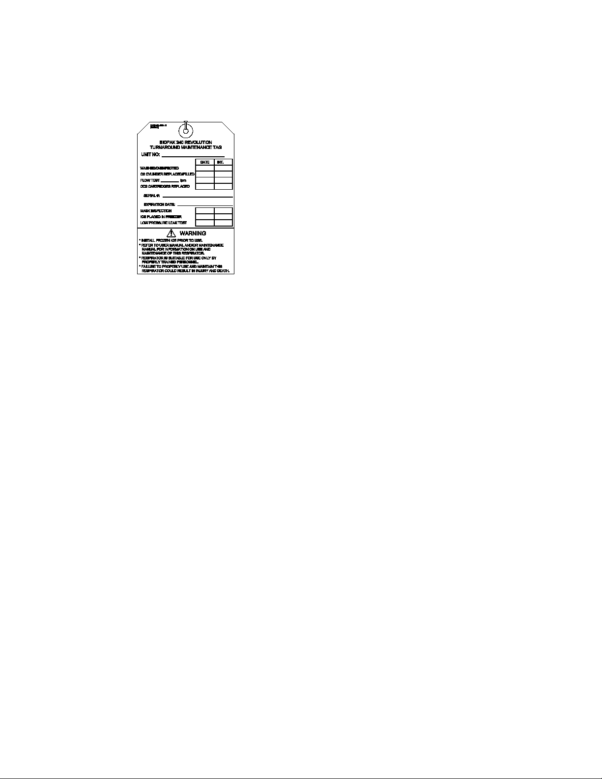
1.1 Maintenance Tag
Obtain a maintenance tag supplied with
replacement carbon dioxide scrubbers.
The maintenance tag shall be completed as
directed in this procedure and then attached
to the apparatus in a prominent location to
show completion of all maintenance steps.
Record the apparatus identification onto the
tag.
1.2 Disassembly
Immediately after completion of BioPak,
use, remove the used CO2scrubber
canisters, scrubber moisture pad and
disconnect the demand and constant add
lines from the center section to prevent
migration of moisture into the manifold
assembly.
Disassemble the apparatus to prepare for
cleaning and disinfection. Identify any
apparatus damage and repair as needed.
Repairs beyond the scope of the Benchman
should be referred to Biomarine.
1. Remove the upper housing.
2. Remove the coolant lids and coolant ice.
3. Remove the oxygen cylinder, making
sure the seal washer, if utilized, remains
in place, and install the regulator wash
cover supplied with the service kit.
It is acceptable to leave the oxygen
cylinder in place until after washing and
disinfecting has been completed to
prevent ingress of contaminates into the
high pressure plumbing of the BioPak.
4. Remove the facemask from the
breathing hoses.
5. Remove the breathing hoses from the
breathing chamber.
6. Remove the center section lid.
7. Remove and discard the two carbon
dioxide scrubber components and the
scrubber moisture pad.
8. Remove the moisture sponges and the
PCM.
9. Disconnect the electrical line and both
pneumatic connections to the center
section. Use care when handling the
center section. Avoid sharp objects and
rough surfaces that could damage the
rubber diaphragm.
10. Remove the four quarter-turn fasteners
and remove the center section.
1.3 Cleaning/Disinfection
Use only cleaners and disinfectants that are
approved by Biomarine.
The apparatus must be cleaned and
disinfected as soon as possible after each
use. If cleaning is not immediately possible
after use, at a minimum remove and discard
the carbon dioxide scrubber and moisture
pad, remove the moisture control foam
pads, disconnect both the constant and
demand add lines and temporarily store the
BioPak with the center section lid open to
prevent the growth of mold or mildew.
DO NOT submerge the electronic monitor
housing.
DO NOT allow any fluids to contact the
input port of the pressure regulator.
1. Clean the upper and lower housings, ice
canisters and coolant lids and all
connected components with a mild soap
and water mixture if necessary.
2. Mix the disinfectant with clean water as
directed on the package.
3. Submerge the facemask, hoses with
facemask connector, center section lid,
center section, PCM and moisture
sponges into the disinfectant solution.
Allow the components to be wetted on
all surfaces.
BioPak 240R Benchman Manual
47C091, Revision D
Page 9 of 46
Install a Demand Port Wash Plug,
supplied with the service kit, to the
demand port of the center section to
keep water from migrating into the
demand valve.
DO NOT allow the mask to soak in
cleaning solutions for extended periods.
Extended soaking can cause
delamination of the anti-fog film.
4. Thoroughly rinse all components in
clean water to remove all disinfection
solution. It is extremely important to
fully rinse the facemask of all
cleaning solution.
5. Allow all components to dry either by
air-drying, heated drying or through the
use of adryer system. Heat-assisted
drying temperatures shall not exceed
120oF (50oC).
6. Date and initial the maintenance tag
under Washed/Disinfected.
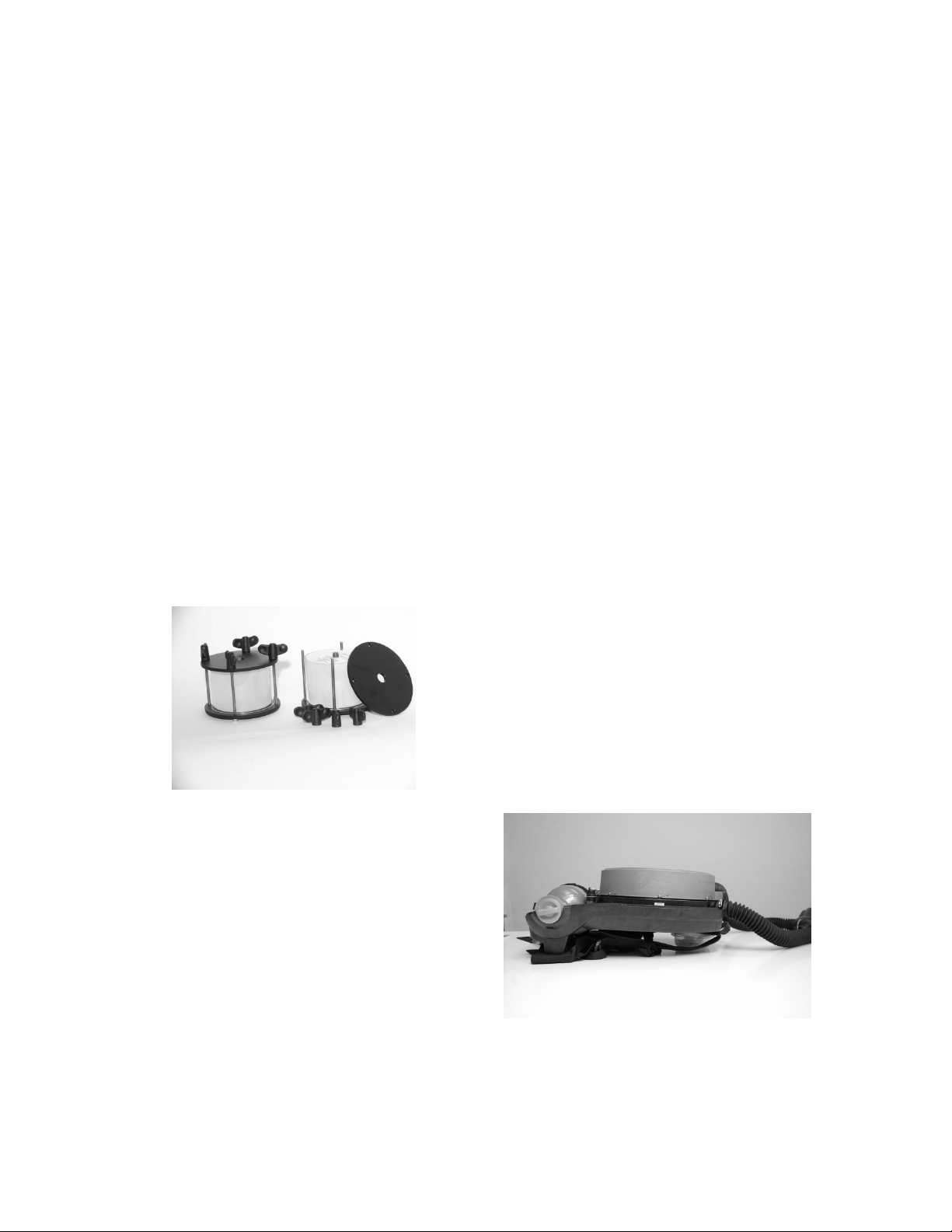
1.4 Coolant Canister
The coolant canisters must be frozen before
use.
1. Place the cleaned and dried canisters
into the freeze form and secure the lid.
2. Place the freeze forms onto a level
surface in a freezer for a minimum 8-
hour period at a temperature of 10oF
(-12oC) or less.
3. Date and initial the maintenance tag
under Ice Placed in Freezer.
1.5 Oxygen Cylinder
The oxygen cylinder must be fully charged
to 3000 psi (207 bar) with oxygen before
use.
Oxygen used to supply or charge the
breathing apparatus must be medical or
aviation grade oxygen with moisture content
less than 50 mg/m3at 3000 psi (207 bar).
The composition of suitable oxygen is given
below.
Oxygen: 99.5% minimum mole
Carbon Dioxide: 300 ppm maximum
Carbon Monoxide: 10 ppm maximum
The purity/quality of oxygen used to supply
and charge the cylinder should be tested
periodically in accordance with national
regulations.
National regulations must be observed.
Oxygen will enhance the combustion of
other materials. Personnel dealing with
compressed oxygen and compressed
oxygen cylinders must be fully trained in
the use and handling of compressed
oxygen.
1. Obtain the proper cylinder fill adapter
need to connect the oxygen cylinder to
the booster pump.
2. Connect the cylinder to the booster
pump and charge to 3000 psi (207 bar)
pressure with medical or aviation grade
oxygen, according to pump
manufacturer’s instructions.
1.6 Facemask
1. Inspect the components of the facemask
and replace as required.
2. Do not apply anti-fog solutions to the
lens of the facemask.
3. Date and initial the maintenance tag
under Mask Inspection.
1.7 Assembly
1. Position the BioPak in a level position as
depicted above, by propping up the
handle end of the lower housing.
BioPak 240R Benchman Manual
47C091, Revision D
Page 10 of 46
2. Install the center section making sure to
properly seat the three springs onto the
diaphragm.
3. Lock the center section into position
using the four quarter-turn fasteners.
4. Connect the electrical and pneumatic
lines to the center section. Verify the
presence of an o-ring seal on each
pneumatic line connection.
5. Position the fully dry moisture sponges
into the center section. The sponges
must be fully dry to prevent the growth
of mold within the apparatus.
6. Install the PCM into the breathing
chamber.
7. Install the center section lid and latch to
secure. If pre-packing the carbon
dioxide scrubbers complete section 1.12
then return to step 8 of this section.
8. Install the breathing hoses to the
breathing chamber and secure with
clamps making sure mask connector is
sitting with an approximate 45oangle
and the flow direction arrows are facing
up.
9. Install the storage plug into the
facemask connector.
10. Install the oxygen cylinder and secure
with the hold down strap.
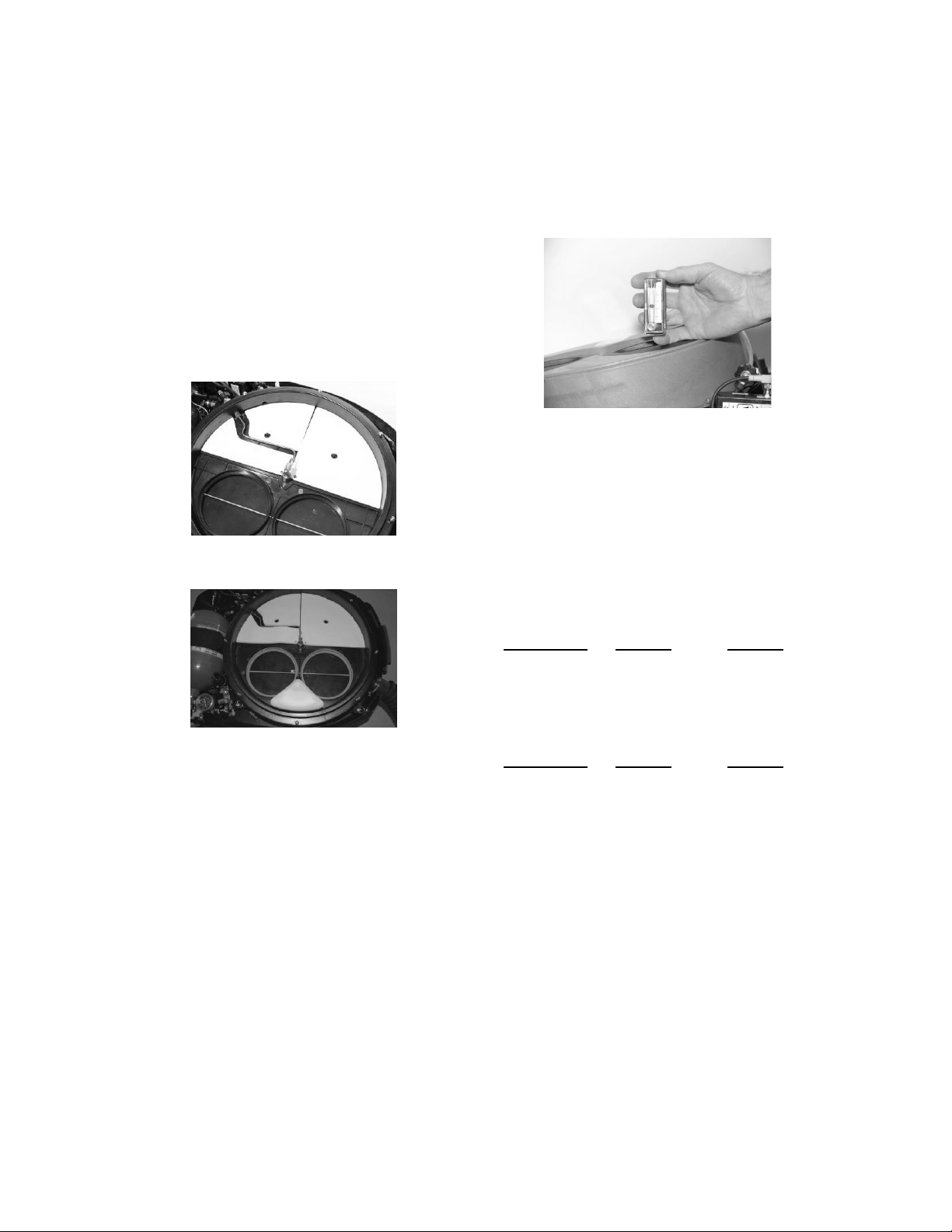
1.8 Constant Flow Test
1. Disconnect the constant add feed line to
the center section (green line) and
connect the test flowmeter from the
service kit to the open end of the feed
line.
2. Open the oxygen cylinder valve and
observe flowmeter while holding it in a
vertical and level position. The
flowmeter shall indicate a flow as per
the table below when reading the center
of the flowmeter ball.
If the flow does not meet the requirements of
the table below, the flow restrictor will need
replacement.
Cylinder 0-5280 ft +5280 ft
Pressure, Flow, Flow,
psi lpm lpm
1500-2000 1.8-2.4 1.9-2.6
2000-3000 1.9-2.5 2.0-2.8
Cylinder 0-1600 m +1600 m
Pressure, Flow, Flow,
bar lpm lpm
100-150 1.8-2.4 1.9-2.6
150-207 1.9-2.5 2.0-2.8
3. Enter the measured flow rate, date and
initial the maintenance tag under Flow
Test____ lpm.
4. Close the oxygen cylinder valve, remove
the test flowmeter and reconnect the
constant add feed line to the center
section.
BioPak 240R Benchman Manual
47C091, Revision D
Page 11 of 46
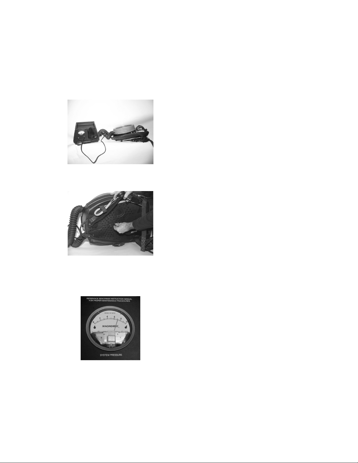
1.9 Low Pressure Leak Test
1. Attach the open end of the rubber tubing
to the input port of the service kit and
close the bleed valve on the service kit.
2. Remove the storage plug from the
breathing hoses and install the leak test
adapter to the hose adapter.
3. Insert two test keys from the service kit
in the keyholes in the back of the lower
housing.
4. Open the oxygen cylinder valve and
depress the bypass valve until the test
kit displays a pressure of 3.0” water
column, then immediately close the
oxygen cylinder valve.
5. Activate the emergency bypass valve to
empty all gas into the breathing
chamber and raise the pressure reading
to between 6 and 8” water column. DO
NOT over pressurize, vent as needed.
6. After the test gauge stabilizes, note the
exact pressure reading of the service kit
and allow the apparatus to sit
undisturbed for 60-seconds. The
apparatus pressure shall not drop more
than 0.2” water column in the 60-second
period, restart the timed test if the
pressure on the service kit increases.
If the oxygen cylinder is not closed the
pressure reading will continue to rise and
potentially damage the breathing
chamber.
If the apparatus pressure drops more
than 0.2” in the 60-second there is a leak
that must be located and repaired.
7. Open the service kit bleed valve.
8. Remove the leak test adapter from the
hose adapter to vent the apparatus.
9. Replace the storage plug.
10. Remove the two test keys from the
rear of the lower housing.
11. Date and initial the maintenance tag
under Low Pressure Leak Test.
1.10 Alarm Test
1. While observing the pressure gauge,
open the oxygen cylinder valve. The
cylinder must be filled with a minimum of
1500 psi (100 bar) pressure for this test.
2. When the oxygen cylinder is opened the
LED shall cycle RED, GREEN, BLUE
with the horn sounding. The LED will
then flash GREEN and the horn will be
silent.
3. The pressure gauge will reach full
reading in approximately 60-seconds.
4. Close the oxygen cylinder and allow the
BioPak to slowly reduce pressure while
observing the pressure gauge and LED
indications. The LED should turn to a
flashing red with a horn sounding when
the pressure gauge reads between 650-
1000 psi (45-69 bar). The LED will
cease when the pressure gauge reads
less than 25 psi (1.7 bar).
5. Verify that the oxygen cylinder is fully
charged to 3000 psi (207 bar) and top
off if necessary.
6. Date and initial the maintenance tag
under O2 Cylinder Replaced/Filled.

BioPak 240R Benchman Manual
47C091, Revision D
Page 12 of 46
1.11 Upper Housing
1. Replace the upper housing onto the
apparatus.
2. If the carbon dioxide scrubbers have not
been installed into the apparatus then
leave the maintenance tag CO2
Cartridges Replaced field blank.
See section 1.12 concerning procedures
for pre-packing the carbon dioxide
scrubber into the apparatus during turn
around maintenance.
3. Tie the completed maintenance tag to
the BioPak in a conspicuous and
consistent location.
1.12 Carbon Dioxide Scrubber Pre-
Packing Procedure
The carbon dioxide scrubbers can be pre-
packed into the apparatus during turn
around maintenance if so desired.
Pre-packed carbon dioxide scrubbers
may only be stored in the apparatus for a
maximum period of 1-year.
Moisture sponges must be installed dry
when pre-packing the BioPak.
DO NOT pre-pack any BioPak that will be
stored at temperatures at or below
freezing (32oF/0oC).
Apparatus that are pre-packed with the
carbon dioxide scrubber shall be stored
within the specified storage temperature
and humidity levels and must be sealed
air-tight in the apparatus.
1. Inspect the “use by date” of the carbon
dioxide scrubber to ensure that it is
current. Record the carbon dioxide
scrubber serial number and “use by
date” date onto the maintenance tag or
affix the scrubber label to the back of
the tag.
2. Open the sealed bag and inspect each
canister to verify the presence of an o-
ring properly seated into the lower
groove.
3. Install two carbon dioxide scrubber
canisters into the breathing chamber
making sure that they are proper aligned
and fully seated into position.
4. Remove the moisture pad from the
sealed pouch and install it into the breathing
chamber as shown.
Proper moisture pad installation.
WARNING: Failure to install the moisture
pad can lead to scrubber flooding that
will result in elevated carbon dioxide
levels in the breathing gas that may lead
to injury or death.
WARNING: Users ARE NOT permitted to
mix versions of the OrbSorb®within a
BioPak. Scrubber canisters installed into

BioPak 240R Benchman Manual
47C091, Revision D
Page 13 of 46
the BioPak for use must be of exactly the
same shape and type.
5. Install and secure the breathing
chamber lid.
6. Date and initial the maintenance tag
under CO2 Cartridges Replaced.
Record the expiration date of the
scrubber onto the maintenance tag.
The “use by date” of pre-packed carbon
dioxide scrubbers will be the shorter time
period between the following two factors:
1-year from date of scrubber installation
into BioPak, or,
“use by date” provided on packaging of
carbon dioxide scrubber.

BioPak 240R Benchman Manual
47C091, Revision D
Page 14 of 46
2 Long Term Maintenance
Procedure
In addition to normal turn around
maintenance, the apparatus shall be visually
inspected and pressure tested on a periodic
basis as outlined below:
Used 1 time or more/month: monthly
Used <1 time/month: quarterly
In Long Term Storage: every 6 months
A Maintenance Log Sheet is provided in this
manual to assist in tracking long-term
maintenance procedures.
2.1 Visual Inspection
Remove the upper housing and visually
inspect the apparatus for signs of wear,
abuse, loose connections or other damage.
Repair as necessary.
Verify that the apparatus is properly sealed
against the ambient environment by the
presence of the storage plug.
2.2 Demand Valve Functional Test
1. Vent the BioPak of all internal pressure.
2. Open the oxygen cylinder and listen for
the sound of gas escaping into the
breathing chamber. The sound will last
approximately 1-3 seconds. This
signals that the demand has properly
opened.
3. After 1-3 seconds the sound of gas
escaping into the breathing chamber
must cease. This signals that the
demand valve has properly closed.
2.3 Constant Flow Test
1. Perform the test as described in Section
1.8.
2.4 Vent Valve Functional Test
1. Replace the seal plug from the
facepiece adapter with the leak test
adapter from the test kit and connect the
barb of the adapter to the barb of the
service kit using rubbing tubing.
2. Depress the emergency bypass valve in
several short bursts. Observe the
pressure reading on the service kit. The
apparatus pressure should remain at or
below 2” water column pressure after
releasing the emergency bypass valve.
2.5 Low Pressure Leak Test
1. Perform the test as described in Section
1.9.
2.6 High Pressure Leak Test
1. Place the apparatus on a flat surface.
Ensure that the test keys of the Low
Pressure Leak Test have been
removed. The oxygen cylinder must
be fully charged to above 1500 psi
(103 bar).
2. Open the oxygen cylinder valve and wait
until the apparatus pressure gauge has
reached its final reading.
3. Apply an oxygen-safe leak detection
fluid to each plumbing connection. Wait
60-seconds then inspect each
connection for the sign of bubble
formation.
4. Repair any leaking joint or replace the
leaking components. Repairs must be
performed with the BioPak fully
vented of all internal pressure.
5. Close the oxygen cylinder valve and
depress the emergency bypass valve to
depressurize the apparatus.
Note: A digital high-pressure test
apparatus is available from
Biomarine that will eliminate the
need for the use of leak detection
fluid during testing.

BioPak 240R Benchman Manual
47C091, Revision D
Page 15 of 46
2.7 Emergency Bypass Valve
Functional Test
1. Open the oxygen cylinder and depress
the emergency bypass valve for 1-2
seconds. The sound of gas escaping
into the breathing chamber shall be
heard whenever the valve is depressed
and shall cease whenever the valve is
released.
2. Close the oxygen cylinder.
2.8 Alarm Test
1. Perform the test as described in Section
1.10.
2.9 Maintenance Tag Validation
1. Inspect the maintenance tag that should
be attached to the apparatus in a
conspicuous and consistent location.
Verify that all portions of the tag are
properly completed.
2. Verify that the apparatus oxygen
cylinder is fully charged to 3000 psi (207
bar) and top off if necessary.
3. Replace the upper housing.

BioPak 240R Benchman Manual
47C091, Revision D
Page 16 of 46
3. General Service Procedures
3.1 Scheduled Component Inspection
Breathing Diaphragm:
Annually, remove the center section and
disconnect the diaphragm from the center
section by loosening the clamp. Inspect the
diaphragm for signs of wear, cracking or rot.
Disassemble the vent valve, clean and
inspect all components and lubricate as
needed.
Diaphragm Alignment: Proper diaphragm
alignment is depicted below. Note the
positioning of the three large holes in the
diaphragm plate in relation to the breathing
chamber mounting feet and the breathing
hoses. Reference diagram in Section 5.6.
Facemask: Inspect all rubber components
for signs of wear, tears, rips, cracking or rot.
Inspect the lens for signs of cracking,
breakage, crazing or other damage.
Breathing Hoses: Inspect for signs of
wear, tears, rips, cracking or rot.
O-ring Seals: If the apparatus has passed
the high and low pressure leak tests the o-
ring integrity is acceptable. Reference
Appendix A for a schedule of o-ring seal
inspection and lubrication.
3.2 System Lubrication
Leaks discovered during high and low
pressure testing are often caused by
damaged or improperly lubricated o-rings.
Replace faulty o-rings and follow the guides
below for o-ring handling and lubrication.
•Never pry o-rings from glands with a
screwdriver. Remove o-rings by
hand or using the pick tool provided
in the service kit. Pick tool should
only be used for o-ring that are
being replaced.
•Unless otherwise directed, do not
lubricate o-rings while they are still
seated within their gland.
•Do not use heavy coats of
lubrication. Proper o-ring lubrication
will result in a shiny surface without
lumps.
•Do not stretch or deform o-rings
during handling.
•Visually inspect under bright lighting
or inspect by feel, o-rings for signs
of damage such as nicks, cuts, tears
or abrasion.
•Christo-Lube™ and MolyKot or Dow
111™ are the only lubricants
approved for use in the apparatus.
Reference Appendix A for
lubrication type for each seal.
•NEVER lubricate the seal that sits
between the oxygen cylinder and
the pressure regulator.
3.3 Oxygen Cylinder
The cylinder should be inspected regularly
for signs of damage to the outer wrapping.
Cylinders that are cracked, flaking or show
exposed fibres should be immediately
retired from service. Inspect cylinders per
publication CGA 6.2.
Cylinders require periodic hydro-static
testing per national requirements. Intervals
are every 5-years from the date of
manufacture. Cylinder testing should be
conducted by an authorized testing facility,
with experience testing oxygen cylinders.

BioPak 240R Benchman Manual
47C091, Revision D
Page 17 of 46
Cylinders that have been hydro-static tested
shall be cleaned for high-pressure oxygen
service as per national standards.
Cylinders must be retired from service 15-
years after the date of manufacture.
3.4. RMS Battery Replacement
Procedure
The alarm system battery shall be replaced
after 200-hours of use, after 6-months or
after the alarm system low battery alarm
(RED, GREEN, BLUE flashes with
corresponding horn sounding), whichever
occurs first.
1. Remove the upper cover.
2. Disconnect the electrical line to the
center section.
3. Use two 7/16” wrenches from the
service kit to remove the light guide from
the alarm monitor housing. DO NOT
allow the fitting anchored to the alarm
housing to rotate.
4. Inspect the housing for cracks or
damage. Dust-tight and water-tight
integrity are required for use in
potentially explosive atmospheres. The
alarm module will require
replacement if any damage to the
housing is discovered.
5. Remove the battery cover. Inspect the
cover and gasket for cracks or damage.
The battery cover door will need to
be replaced if any damage is found.
6. Remove the battery from the alarm
housing and replace with a fresh
battery. Inspect the interior of the
battery compartment for the presence of
corrosion, liquid or dust. Clean if
necessary or replace the alarm module.
7. Install the replacement battery into the
battery compartment making sure to
proper align the battery poles.
Use only battery types as specified for
replacement.
8. Replace the battery cover making sure
that the gasket is properly positioned
and that the gasket is not damaged in
any way. The battery door will only fit in
one orientation on the module.
9. Install the alarm housing into the
apparatus.
10. Use two 7/16” wrenches from the
service kit to install the light guide from
the alarm monitor housing. DO NOT
allow the fitting anchored to the alarm
housing to rotate. The light guide shall
be positioned so that it is directed
straight down towards the lower
housing.
11. Connect the electrical line from the
center section to the alarm housing.
12. Conduct the Alarm Test as described in
section 1.10.
13. Install the upper housing.
3.5 Flow Restrictor Replacement
Procedure
1. Remove the upper housing and vent the
BioPak of all internal pressure.
2. Use the ¼” hex driver from the service
kit to the remove the flow restrictor. Be
sure to remove and discard the head
gasket and o-ring of the existing flow
restrictor.
3. Use the ¼” hex driver from the service
kit to the install a replacement flow
restrictor.
Use caution when installing the flow
restrictor to insure that o-ring does not
roll out of its gland.
4. Perform the high-pressure leak test as
directed in long term maintenance.
5. Perform the constant add test as
directed in turn around maintenance.
6. Replace the upper housing.

BioPak 240R Benchman Manual
47C091, Revision D
Page 18 of 46
3.6 Factory Service and Training
Factory service and personnel User and/or
Benchman Training can be provided by
contacting the location listed below.
Biomarine, Inc.
ATTN: Service Department
456 Creamery Way
Exton, PA 19341-2532
USA
Tel: (610) 524-8800
Extensions 146 or 163
Fax: (610) 524-8807
Web: www.BioPak240r.com
•Customers can also contact their
local authorized Biomarine
Distributor for training, product
support, emergency support or
maintenance.
•The BioPak 240R-NIOSH User and
Benchman manuals can be
provided in electronic format upon
request.
•Reference documentation supplied
with sales order for standard terms
of warranty.
•Training posters, manuals, MSDS
data and other training materials are
available for download from the
Biomarine website.
•Contact Biomarine prior to
returning any equipment.
To better serve your needs, please provide
the following information when contacting
Biomarine.
•Apparatus Serial Number
(Located internal to the BioPak,
beneath the oxygen cylinder)
•Date of purchase
•Approximate number of uses
•Description of problem
•Actions taken to correct problem
•Contact name, address and phone
number with area or country code
and email address
•Please provide your current email
address with all service
correspondence.
4. STORAGE GUIDELINES
Follow the guidelines below for proper
storage of the apparatus.
•Storage plug shall be installed.
•Never store a wet apparatus. The
apparatus must be fully dry before
storage to prevent the growth of
mold, germs and bacteria.
•Never store an apparatus that has
not been fully cleaned and
disinfected.
•Store in a location free from impact
that could cause damage to the
apparatus.
•Store in the stated conditions of
ambient temperature and relative
humidity.
•Store in a location that will not
submerge the apparatus.
•Long Term Storage (storage of
BioPak for periods exceeding 6-
months without use): Follow all of
the above guidelines. The BioPak
should not be placed back into
service until all the procedures
associated with Turn Around and
Long Term maintenance have been
performed and passed.

BioPak 240R Benchman Manual
47C091, Revision D
Page 19 of 46
5. PARTS LIST
5.1 Top Assembly
ITEM # QTY. PART NUMBER DESCRIPTION
1 1 --- AV3500 Facemask Assembly-See Section 5.2
2 1 ---- PRO PP Facemask Assembly-See Section 5.3
3 1 B6-02-5002-18-0 Upper Housing Assembly
4 2 B2-02-4000-39-0 Coolant Lid
5 2 B6-02-5002-37-0 Ice Canister
6 2 B2-02-7001-09-0 Breathing Hose-See Section 5.4
7 1 B6-02-5002-04-3 Center Section Lid Assembly-See Section 5.5
8 1 B6-02-5003-69-0 CO2Scrubber Canister2
9 1 B6-02-5003-34-0 Scrubber Moisture Pad2
10 1 B6-02-5002-07-5 Center Section Assembly-See Section 5.6
11 1 --- Pneumatic Assembly-See Section 5.8
12 1 B6-01-5000-05-0 Alarm Monitor-See Section 5.10
13a 1 B6-02-5001-98-0 Green O2Cylinder, Empty3-See Section 5.11
13b 1 B6-02-5001-98-1 Green O2Cylinder, Full3-See Section 5.11
13c 1 B6-02-5002-06-0 Black/White O2Cylinder3, Empty-See Section 5.11
13d 1 B6-02-5002-06-1 Black/White O2Cylinder3, Full-See Section 5.11
14a 1 B6-02-5003-73-0 Green O2Cylinder, Empty4-See Section 5.12
14b 1 B6-02-5003-73-1 Green O2Cylinder, Full4-See Section 5.12
14c 1 B6-02-5003-74-0 Black/White O2Cylinder4, Empty-See Section 5.12
14d 1 B6-02-5003-74-1 Black/White O2Cylinder4, Full-See Section 5.12
15 1 B6-02-5002-28-0 Lower Housing Assembly-See Section 5.13
16a 1 B2-02-7001-24-0 Harness Assembly-Flame Rated5
16b 1 B2-02-7001-87-0 OTS Harness Assembly-Flame Rated5
17 2 B6-02-5002-40-0 Ice Canister Freeze Form-See Section 5.15
18 1 B5-06-6000-14-0 User Manual-ENGLISH6
19 1 B5-06-6000-15-0 Benchman Manual-ENGLISH6
20 opt. B2-06-6000-17-0 Hard Transit Case (not depicted)
21 opt. B2-02-7000-39-0 Soft Transit Case (not depicted)
22 1 B2-02-4001-50-0 AV3500/PRO PP Storage Plug
23 1 B6-02-5002-54-0 Cylinder Fill Adapter, CGA 540 Male7
24 1 B6-02-5002-55-0 Cylinder Fill Adapter, CGA 540 Female7
25 1 B6-02-5002-53-0 Cylinder Fill Adapter, G ¾-A Male7
26 1 B6-02-5002-66-0 Cylinder Fill Adapter, W21.87
27 1 B6-02-5002-41-0 Phase Change Heat Exchanger (PCM)
28 1 B2-02-7001-07-0 Moisture Absorbent Pad Set
Note:
1. The BioPak 240R respirator is supplied with a cardboard/foam shipping box. Hard or soft transit cases are to be
ordered separately.
2. CO2Scrubber Canister, part number B6-02-5003-69-0, will supply four sets of canisters, four sets of moisture
pads, and maintenance tags for four separate single uses.
3. Indicated oxygen cylinders utilize a flat sealing washer between the cylinder outlet and the pressure regulator.
4. Indicated oxygen cylinders utilize a captured o-ring to seal between the cylinder outlet and the pressure regulator.
5. There are two harness styles available. The OTS harness will route the remote gauge over the shoulder of the
user and provides form mounting of tools, battery cap lamp battery and a self-rescue device.
6. Alternate language manuals are available. Contact Biomarine Representative for details.

BioPak 240R Benchman Manual
47C091, Revision D
Page 20 of 46
5.1 Top Assembly (continued)
7. The following will detail use of the Cylinder Fill Adapters, items 22, 23, 24 and 25.
Item 22, Cylinder Fill Adapter, CGA-540 Male
B6-02-5002-54-0
This connector will adapt a CGA-540 female
connection to the BioPak 240R cylinder.
Item 23, Cylinder Fill Adapter, CGA-540 Female
B6-02-5002-55-0
This connector will adapt a ¼ NPT female port to a
CGA-540 female connection.
The above picture shows the CGA-540 Male and
Female adapters connected together. This
arrangement will provide adaptation from a ¼ NPT
female port to the BioPak 240R cylinder.
Item 24, Cylinder Fill Adapter, G ¾-A Male
B6-02-5002-53-0
This adapter will provide direct adaptation from a
female G ¾-A connection (commonly found on
European booster pumps) to the BioPak 240R
cylinder.
Item 25, Cylinder Fill Adapter, W21.8
B6-02-5002-66-0
This adapter will provide direct adaptation from a
female W21.8 connection (commonly found on
Drager booster pumps) to the BioPak 240R
cylinder.
Other manuals for BioPak 240 REVOLUTION
2
This manual suits for next models
1
Table of contents
Other Biomarine Diving Instrument manuals


