biomotum SPARK User manual

USER MANUAL
Biomotum SPARK
This user manual is provided as a comprehensive guide and reference for using
the Biomotum SPARK System.
If you need further assistance please contact the Biomotum clinical & technical
support team (M-F: 8 am- 4 pm Pacific Time):
(800) 566-2531
Caution: Investigational device. Limited by Federal law to investigational use.
www.biomotum.com
REC-184 Version 0 Page 1 of 39

TABLE OF CONTENTS
CHAPTER 1: INTRODUCTION 3
INDICATIONS FOR USE 3
CONTRAINDICATIONS FOR USE 3
DEVICE DESCRIPTION 3
OPERATING PRINCIPLE 5
SYSTEM CALIBRATION 7
NOTATIONS USED 7
SYMBOLS USED 8
WARNINGS & CAUTIONS: 8
CHAPTER 2:PREPARE THE SPARK FOR USE 10
SAFETY CHECK PROCEDURES 10
BATTERY USE 10
CHOOSING FOOTPLATE SIZE 12
ATTACHING/REMOVING THE FOOTPLATE 13
ATTACHING AND ADJUSTING THE CALF CUFF 14
CHAPTER 3: DONNING THE SPARK 16
PUTTING ON THE ANKLE/FOOT ASSEMBLY 17
DONNING THE WAIST PACK 18
TENSIONING THE ACTUATOR CABLES 18
SECURING THE THIGH STRAPS 19
USING THE SHOULDER HARNESS (OPTIONAL) 21
USING THE FOOTPLATE STRAPS (OPTIONAL) 21
SYSTEM CHECK 22
CHAPTER 4: SETTINGS, CALIBRATIONS AND USE 23
TURNING ON AND PAIRING THE SPARK 23
INPUT USER SETTINGS 24
INPUT WALKING SETTINGS 26
CALIBRATING THE SYSTEM 28
USING IN-TRIAL FEATURES 29
SESSION SUMMARY OVERVIEW 32
CHAPTER 5: ERROR MESSAGES, TROUBLESHOOTING 33
DEVICE SETUP 33
WALKING 34
SOFTWARE 35
CHAPTER 6: CLEANING & MAINTENANCE 37
CLEANING 37
MAINTENANCE 37
www.biomotum.com
REC-184 Version 0 Page 2 of 39

CHAPTER 1: INTRODUCTION
Caution: Investigational device. Limited by Federal law to investigational use.
INDICATIONS FOR USE
The Biomotum SPARK orthotically fits the lower limbs and trunk. The SPARK is
intended for use in rehabilitation institutions under the supervision of a trained
healthcare professional to assist ambulatory functions, and to temporarily help
improve ambulation upon completion of a gait training intervention. The device
is intended for adolescents with Cerebral Palsy (ages between 12-21 years old) who
are able to walk for 6 minutes with or without a walking aid (e.g., AFO and/or
walker), and who do not have a musculoskeletal condition that would prevent the
safe use of ankle assistance or resistance .
The Biomotum SPARK is not intended to be used on participants under 12 years
old or over 21 years old; it has not been tested in these populations.
The Biomotum SPARK is not intended to be used for running or other sport
activity.
The Biomotum SPARK is not intended to be used in individuals with hypertonicity
or stiff muscles.
CONTRAINDICATIONS FOR USE
●Musculoskeletal conditions that would prevent the safe use of ankle
assistance or resistance, including:
○<20 degrees of passive ankle plantarflexion range of motion
○Knee extension or ankle dorsiflexion contractures >15 degrees
●Orthopedic surgery on foot, ankle, or leg completed in the prior 6-months
●Diagnosis of severe osteoporosis (low bone density)
●Body mass index <5th percentile or >95th percentile
●Cardiovascular disease that prevents mild-moderate physical activity
DEVICE DESCRIPTION
The Biomotum SPARK consists of the following components:
●Waist Pack: The waist pack houses the motors,battery, and control
hardware (motor drivers, microcontroller, Bluetooth hardware, and
measurement hardware) and is worn using a comfortable belt and
harness with magnetic clasps. The power button to turn the device on and
off is located on the bottom of the waist pack.
www.biomotum.com
REC-184 Version 0 Page 4 of 39

●Cable Transmission: The cables transfer torque from the motors to the
ankle actuator. The cable transmission system is worn using thigh straps to
prevent the cables from catching on the environment.
●Ankle Actuator: The ankle actuator is a lightweight, single
degree-of-freedom rotational joint that interfaces with the wearer’s shank
and foot to transfer torque from the motors to the wearer’s ankle joint. The
ankle actuator is held on the shank using a comfortable shank cuff. A
footplate attached to the ankle actuator fits in the wearer’s shoe and
moves the foot to provide assistance or resistance to the wearer’s ankle
joint. Shank cuffs and footplates are interchangeable and must be fitted to
the wearer so that they are snug yet comfortable. Sensors in the ankle
actuator measure the torque transmitted by the device; sensors on the
footplate detect whether the wearer’s foot is in contact with the ground.
Both sensors are integral to the function of the device and must be
handled with care.
●Control Interface: The control interface is an iOS/Android tablet preloaded
with a proprietary application that controls the device wirelessly over
Bluetooth. The application stores wearer information and data, starts and
stops device sessions and trials, performs device calibration, allows the
clinician/researcher to adjust device settings, and uploads collected data to
a cloud service. The device cannot be used without the control interface.
The control interface must remain within 30 feet (9 meters) of the device at
all times to maintain Bluetooth connection. The device will continue to
function when disconnected, but the device settings cannot be changed,
sessions and trials cannot be ended, and data collected while the control
interface is disconnected will not be stored or saved. Normal operations will
resume once the device is within range of the control interface.
The Investigational Use SPARK device includes an iOS tablet pre-loaded with the
Biomotum application (app).
The SPARK device is also provided with the following tools:
●2.5mm hex screwdriver, used on the safety bolt for the metal
quick-connect bracket on the footplate
●1.8mm slotted screwdriver, used on the screw for the cuff quick-release
mechanism
Materials needed but not provided:
Plastic card, key, or slot-head screwdriver, to check the tension in the actuator
cables.
www.biomotum.com
REC-184 Version 0 Page 5 of 39

An illustration of the Biomotum SPARK device is included below.
Figure 1. Biomotum Spark System Components
OPERATING PRINCIPLE
SPARK’s hybrid control system adjusts assistance or resistance across variable
terrain and walking speeds. Hybrid control uses force sensors embedded into
each footplate and provides torque that is proportional to the instantaneous
demand placed on the ankle joint (i.e., the net moment generated by muscles
and other biological tissues crossing a joint). The peak (maximum) torque that
can be applied by the SPARK is set by the user. In simple terms – walking faster or
slower results in a greater or smaller registered foot sensor force. The amount of
assistance or resistance provided to the user by the SPARK device is
automatically adjusted proportional to the change in foot sensor measurement
and peak torque setting, in real time.
www.biomotum.com
REC-184 Version 0 Page 6 of 39

Hybrid control: Assist to make walking easier.
Resist for precision ankle therapy
Figure 2. SPARK Control System
The SPARK has two modes of operation (“hybrid control”):
●Assistance: Assistance mode provides ankle joint plantarflexion torque
during stance and dorsiflexion torque during swing.
●Resistance: Resistance mode provides ankle joint dorsiflexion torque
during stance.
Ranges for optimal peak stance phase plantarflexor assistance and resistance
levels (0.25-0.30 Nm/kg for assistance and 0.10-0.15 Nm/kg for resistance) were
established during clinical walking testing. The default settings are 0.30 Nm/kg
and 0.12 Nm/kg, for assistance and resistance, respectively. For example, peak
default assistance torque for a participant with a body mass of 75 lbs (34 kg)
would be 8.5Nm. These settings can be customized by the therapist at their
discretion after assessing the user’s gait pattern. Nominal, on-off dorsiflexor
torque can be provided during the swing phase between 0-5 Nm.
SYSTEM CALIBRATION
www.biomotum.com
REC-184 Version 0 Page 7 of 39

The SPARK performs both a static and dynamic calibration each time the SPARK
is donned and used.
The static calibration is performed while the user is standing still, after donning
the SPARK. Device torque is measured by the torque sensors in each ankle
actuator, and is tared during the static calibration to eliminate bias in the
measured torque signal that can affect control of the SPARK system.
The dynamic calibration begins after the user starts walking during a trial.
Dynamic calibration quantifies the pressure threshold used to determine the
stance and swing phases by logging the maximum and minimum pressure
sensor signal for each step taken. The dynamic calibration also quantifies the
baseline peak pressure (average peak pressure during the initial steps).
The prescribed torque profile is generated by taking the instantaneous pressure
sensor signal and normalizing it by the baseline peak pressure value. The
resulting normalized signal is bounded by values 0 and 1.5, with the value 1.0
corresponding to the peak torque setting. For example: if a value of 30% or 15 Nm
is entered in the app, the controller will specify a peak prescribed torque of 15 Nm
when the normalized pressure sensor signal is equal to 1.0.
Assistive/resistive torque is not applied until the dynamic calibration is complete
and the pressure sensor baseline is established.
NOTATIONS USED
Warnings & Cautions used throughout this manual:
WARNING: Describes potential safety hazards, limitations in use as a result of the
potential safety hazard, and steps that should be taken if a safety hazard occurs.
Caution: Information about any special care to be used for the safe and effective
use of the device. Not following this information could lead to damage of the
device or lead to a poor participant experience.
Note: Information that’s helpful to use the device correctly.
www.biomotum.com
REC-184 Version 0 Page 8 of 39

SYMBOLS USED
WARNINGS & CAUTIONS:
WARNING: The SPARK is not waterproof. Do not use it if there is a risk of the
device being exposed to water or other liquids.
WARNING: Risk of falling. Falling could be caused by a loss of control of
ambulation by the participant or therapist as well as malfunction of the SPARK.
The risk of falling can be reduced by having experienced, trained personnel
conduct the therapy sessions using manual assistance. If needed, an overhead
attachment with a safety harness and/or gait belt can be used during treadmill or
over-ground walking. If a participant falls, the device automatically powers off.
WARNING: Use of the SPARK may cause discomfort, skin irritation, bruising, pain,
or unusual swelling which may lead to skin breakdown or abrasions. This risk can
be minimized by proper initial adjustment and regularly checking the skin at
points of contact (waist, shoulders, thighs, calves and feet) during each session.
Adjustments to the device fit and additional padding can be used to decrease the
risk of skin breakdown.
www.biomotum.com
REC-184 Version 0 Page 9 of 39

WARNING: The SPARK may cause an individual to exceed their ankle joint range
of motion, potentially leading to a tendon strain, muscle tear, or avulsion. This risk
is reduced by mechanical stops on the SPARK that prevent the device from
exceeding the normal ankle joint range of motion in the event of an electrical or
software malfunction. Software systems are also in place to further reduce range
of motion to improve fit and comfort during walking. The SPARK should only be
used on individuals who have sufficient ankle joint range of motion (see
Contraindications).
WARNING: Use of the SPARK may cause muscle spasms in participants with
hypertonicity or tight/stiff muscles. Such individuals should not use the SPARK
(see Contraindications).
WARNING: Use of the SPARK could result in bone fractures in individuals with
severe osteoporosis. Individuals with this condition should not use the SPARK.
Caution: Do not use the SPARK on children under 12 years or in adults over 21
years. It has not been tested in these populations.
Caution: Do not use the SPARK for running or other sport activities.
Caution: Ensure the battery is inserted firmly into the waist pack so that no silver
label (other than the pull tab) is showing.
Caution: Do not discharge the battery completely (<15%).
Caution: Make sure the upright & calf cuff are behind the shank and not off to the
side when fitting the device.
Caution: Ensure the purple cables are not twisted when fitting the device.
Twisted cables can negatively affect device performance.
www.biomotum.com
REC-184 Version 0 Page 10 of 39

CHAPTER 2:PREPARE THE SPARK FOR USE
SAFETY CHECK PROCEDURES
Prior to using the SPARK, inspect the following:
●Examine all harness parts (including, but not limited to shoulder, waist and
thigh straps) for evidence of wear or tearing.
●Inspect the waist pack to ensure the battery is securely seated and the
case is intact (i.e., no cracks).
●Ensure the shank cuff is securely fastened to the upright via the quick
release. Purple cables must be secured in the guides of the shank cuff.
●Ensure there is appropriate cable tension at the ankle actuator (see
Tensioning the Actuator Cables), and all bolts are tight with no visible signs
of cable wear.
●Ensure the footplate is securely attached to the ankle actuator and there
are no visible signs of cracking.
BATTERY USE
The Biomotum SPARK uses rechargeable lithium ion batteries designed to last up
to 45 minutes. Follow the charging and use instructions below to optimize the
performance and safety of the system.
●Fully charge the battery prior to use. To confirm if the battery is fully
charged, check the battery charge indicator. The charge indicator displays
5 charge levels: if all 5 are illuminated, the battery is fully charged. If only 1
bar is illuminated and blinking, or all bars are absent, the battery must be
charged.
●To charge the battery, plug the charger into a wall outlet and plug the
battery into the charger. If the LED is solid green, the battery is fully
charged. If the LED is blinking green, the battery is charging. Battery
charging takes approximately 90 min.
●Insert the charged battery into the SPARK.
www.biomotum.com
REC-184 Version 0 Page 11 of 39

Caution: Ensure the battery is inserted firmly into the waist pack so that no silver
label (other than the pull tab) is showing. (Figure 3)
Figure 3. Battery fully inserted into the waist pack
●Avoid discharging the battery completely, as this may damage the battery
and cause it to fail prematurely.
Caution: Do not discharge the battery completely (<15%).
●Ensure the SPARK is turned off when not in use, as leaving it on will drain
the battery.
NOTE: To conserve the battery life during a session, turn off the SPARK if an
individual will not be using it for more than 5 minutes.
www.biomotum.com
REC-184 Version 0 Page 12 of 39

CHOOSING FOOTPLATE SIZE
The footplate is worn inside the shoe.
●Use the sizing chart in Figure 4 to determine the appropriate size footplate.
Use this as a starting point and confirm it is the correct size by having the
participant stand on the footplate (Figure 5). The footplate should be about
the length of the foot, but it can be slightly smaller than the foot if
between sizes.
Figure 4. Footplate sizing chart
Figure 5. Footplate fitting guide where the pink lines indicate foot sensor placement with respect to
the user's foot. The left footplate size is too large for the user. The middle footplate size fits the
user. The right footplate size is too small for the user.
www.biomotum.com
REC-184 Version 0 Page 13 of 39

●After removing the insole/sock liner from the shoe, insert the footplate in
the shoe to confirm that it is the correct length and width (not too long or
wide). The footplate is designed to be used without the shoe insole;
depending on the volume of the shoe, you may choose to use the
insole/sock liner on top of the footplate.
NOTE: Avoid using oversized shoes as the foot and footplate will move within the
shoe and affect the quality of exoskeleton assistance or resistance.
NOTE: The SPARK is designed for use with low-top footwear and will not work
with high-top styles that go above the ankle.
ATTACHING/REMOVING THE FOOTPLATE
The footplate attaches to the ankle actuator via a magnetic quick-connect.
●Use the provided 2.5mm hex screwdriver to unscrew the safety bolt from
the metal quick-connect bracket by rotating the screw counter clockwise
1-2 revolutions. (Figure 6)
NOTE: Do not remove the screw. It only needs to be loosened to insert the
footplate.
●Align the footplate with the studs on the quick-connect bracket, then push
the footplate onto the quick-connect bracket - it will “lock” in place using
magnets.
NOTE: If the footplate does not “lock” into place, check to make sure the
footplate is on the correct side of the device. The device will reject the
footplate if placed on the wrong side.
●Tighten the safety bolt into the quick-connect bracket by rotating the
screw clockwise 1-2 revolutions.
NOTE:Do not overtighten the screw. Tighten until the footplate cannot be
removed from the device.
●To remove the footplate, loosen the safety bolt and pull the footplate away
from the quick-connect bracket.
www.biomotum.com
REC-184 Version 0 Page 14 of 39

Figure 6. Rotate the safety bolt counter clockwise to loosen (left). Rotate the safety bolt clockwise to
tighten (right).
ATTACHING AND ADJUSTING THE CALF CUFF
●Select the calf cuff size that fits snugly around the largest part of the calf
muscle (the cuff goes around the back of the calf) (Figure 7).
NOTE: If the participant is between sizes, use a larger calf cuff and pad the inside
of the cuff with foam to create a snug fit.
Figure 7. Calf Cuff fitting guide. The left cuff size fits the user. The middle cuff size is too small for the
user and has excess space between the user's calf and the cuff. The right cuff size is too large for the
user and the user has excess space between the side of the user’s leg and the cuff.
www.biomotum.com
REC-184 Version 0 Page 15 of 39

●Once the proper size calf cuff has been selected, open the quick-release
lever on the calf cuff (Figure 8) and slide the cuff onto the carbon-fiber
upright. Be sure that the cuff is facing the same direction as the footplate
(i.e., back of the cuff is aligned with the heel of the footplate).
●Adjust the height of the calf cuff so that it aligns with the largest part of
the calf musculature. This can be done by having the participant stand on
the footplate and sliding the calf cuff up or down to the appropriate height.
(Figure 9)
●Tighten the quick-release lever on the calf cuff to secure it in place. Secure
the purple cables by snapping them into the clips on both sides of the cuff
bracket.
●When the quick-release lever on the cuff is secured, the cuff should not
slide up and down. If the cuff moves with the quick-release lever secured,
refer to the Troubleshooting Guide.
NOTE: Calf cuff height adjustment can also be done when donning the SPARK
(after the footplate is in the shoe and the foot is inserted).
Figure 8. Quick release lever in closed (left) and open (right) positions
www.biomotum.com
REC-184 Version 0 Page 16 of 39

Figure 9. Calf cuff aligned with the largest part of the calf musculature
CHAPTER 3: DONNING THE SPARK
The SPARK is designed to contact the participant at the foot, lower leg, and
around the waist. Avoid direct contact of the device with the skin by using the
system with socks and pants. We recommend that the user wear tighter fitting,
athletic apparel to avoid excess material and bulky seams which may cause skin
irritation.
To don the SPARK:
●Have the participant sit in a chair. The participant must not be wearing
shoes.
●Have the participant move forward and sit on the front edge of the chair.
●Put the waist unit behind them on the chair but do not attach it to the
waist yet.
●Bring the cables and ankle/foot assemblies around the waist so that they
are beside each foot.
Caution: Ensure the purple cables are not twisted. Twisted cables can negatively
affect device performance.
www.biomotum.com
REC-184 Version 0 Page 17 of 39

PUTTING ON THE ANKLE/FOOT ASSEMBLY
●Fully plantarflex the device (so that the upright is out of the way of the
lower leg).
Caution: Make sure the upright & calf cuff are behind the shank and not off to the
side.
●Remove the insole/sock liner from the shoes and insert the footplate into
the footwear. (Figure 10)
Figure 10. Footplate correctly inserted into shoe
●Have the participant slide their foot into the shoe while you pull back on
the ankle assembly - this will make it easier to insert the foot without the
footplate sliding forward.
●Tie the shoes (if applicable) so that the foot is secure. If the foot moves in
the shoe after tying, untie and tighten the laces and tie again. Tighten the
shoelaces as much as comfortably possible.
NOTE: The sock liner can be placed over the footplate if there is enough room in
the shoe to accommodate it. It’s better to have the shoe be snug than loose.
●Move the calf cuff forward until it touches the back of the calf. Adjust the
height, if needed. Pull the velcro strap across the front of the shin and
secure it to the other side of the calf cuff. The calf cuff should be snug.
●Confirm that the ankle/foot assembly is comfortable and the participant
can plantarflex and dorsiflex the ankle.
●Repeat with the other foot.
www.biomotum.com
REC-184 Version 0 Page 18 of 39

DONNING THE WAIST PACK
●While the participant is seated, wrap the waist belt around the participant
and latch the belt. The magnetic buckle used on the waist assembly snaps
closed when the ends are brought close to each other. Release the buckle
by sliding the front part of the buckle upwards and the rear part down, in
the opposite direction. (Figure 11)
Figure 11. Operation of waist buckle
●Have the participant stand and tighten the waist strap so that the waist
pack is snug.
NOTE: Raise or lower the waist pack so that the purble cables have just enough
slack to allow the participant to move without the cables becoming fully
extended and pulling on the waist pack. Use the shoulder harness straps if
necessary; see page 22 for instructions.
TENSIONING THE ACTUATOR CABLES
●While the participant is standing, check the tension in the actuator cables
by inserting a rigid object (e.g., key, plastic card, small flathead screwdriver
or similar) in the slot near the top of the pulley covers.
www.biomotum.com
REC-184 Version 0 Page 19 of 39

●Press the rigid object inward and observe the cable movement. Cable
tension is appropriate if the cable aligns with the engraved line on the
pulley cover. If the rigid object contacts the inner wall of the slot, the
cables must be tightened. If the cable can not be pushed to the engraved
line, the cables must be loosened.
Figure 12. Checking and adjusting cable tension
●To tighten the cables, lift the barrel adjusters then turn counter-clockwise,
adjusters are located at the top of the pulley covers. (Figure 12)
NOTE: To rotate, pull up on the barrel adjusters so the extruded gear features
clear the surface. When you are done tensioning the system, make sure the
extruded gear features are properly meshed with the surface so the barrel
adjusters cannot loosen.
●To loosen the cables, lift and tighten the barrel adjusters, turning clockwise.
SECURING THE THIGH STRAPS
●Connect the thigh straps to the purple cables by opening up the Velcro on
each thigh strap (left image) and enclosing the cables securely (right
image), repeat for both legs. (Figure 13)
www.biomotum.com
REC-184 Version 0 Page 20 of 39
Table of contents
Popular Robotics manuals by other brands

ABB Robotics
ABB Robotics IRB 120 Product Manual, Spare Parts
ABB
ABB IRB 360 product manual
MIR
MIR MiR100 quick start

Thames & Kosmos
Thames & Kosmos Robotics Smart Machines Experiment manual
Clementoni
Clementoni Science & Play Cyber-Arm Robotic Blaster Assembly instructions
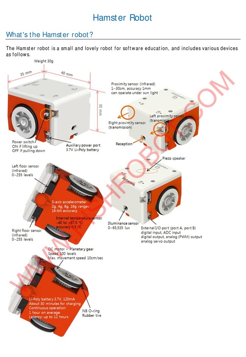
Robomation
Robomation Hamster quick start guide

