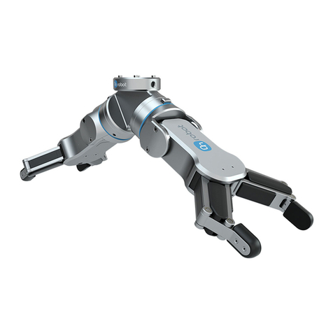
OnRobot VG10 User manual

User Manual
VG10 Vacuum Gripper
Collaborative dual-channel electrical vacuum gripper
Original Instructions (en)
Version 1.1.0


The information contained herein is property of OnRobot A/S and shall not be
reproduced in whole or in part without prior written approval of OnRobot A/S. The
information herein is subject to change without notice and should not be construed as
a commitment by OnRobot A/S. This manual is periodically reviewed and revised.
OnRobot A/S assumes no responsibility for any errors or omissions in this document.
Copyright © 2017–2018 by OnRobot A/S.
The OnRobot A/S logo is trademark of OnRobot A/S.

VG10 Technical Sheet
Technical sheet
Features
•Easy installation, programming and risk assessment
•Optimized for collaborative applications
•Dual grip with two independent gripping zones
•No need for external air or cables down the robot
•10 kg lifting power on airtight and slightly porous surfaces
•Plug’n’Produce in 30 minutes (installation + robot programming)
Minimum
Typical
Maximum
Unit
Vacuum
5 %
-0.05
1.5
-
-
-
80 %
-0.810
24
Vacuum
Bar
inHg
Air flow
0
-
12
Nl/min
Arms adjustment
0
-
270
°
Arm holding torque
-
6
-
Nm
Payload
0
0
-
-
10
22
kg
lb
Recommended workpiece size
10x10
0.5x0.5
-
-
500x500
20x20
mm
in
Vacuum cups
1
-
16
pcs.
Gripping time
-
0.35
-
s
Releasing time
-
0.20
-
s
Foot-inch-foot
-
1.40
-
s
Feature
Vacuum pump
Integrated, electric BLDC
Arms
4, adjustable by hand
Tool changer
Integrated, click-on
Mechanical interface
ISO 9409-1, type 50-4-M6
Pneumatic interface
16x G1/8 internal threads
Electrical interface
8-pole M8
Digital interfaces
URCap (PolyScope ≥ 3.3)
UR scripts (PolyScope < 3.3)
MODBUS RTU
24V I/O
Dust filters
Integrated 50µm, field replaceable
IP Classification
IP54
Dimensions (folded)
146 x 146 x 102 mm
5.75 x 5.75 x 4.00 inch
Dimensions (unfolded)
390 x 390 x 102 mm
15.35 x 15.35 x 4.0 inch
Weight
1.70 kg
3.75 lb

Typical applications
•Pick and place
•Palletizing
•Machine tending
•Material handling
Operating conditions
Minimum
Typical
Maximum
Unit
Power supply
20.4
24
28.8
Volts
Current consumption
50
600
1500
mA
Operating temperature
0
32
-
-
50
122
°C
°F
Relative humidity (non-condensing)
0
-
95
%
Calculated MTBF (operating life)
30000
-
-
hours
What’s in the box?
Everything you need to get started with the VG10 is included:
•1 x VG10 Industrial Robot Vacuum Gripper
•1 x Easy Tool Changer
•1 x 200 mm M8 tool cable
•16 x Fittings for vacuum cups (pre-mounted)
•16 x 30 mm vacuum cups (pre-mounted)
•4 x 40 mm vacuum cups
•4 x 15 mm vacuum cups
•16 x Blind screws
•4 x Torx T30 M6 bolts
•1 x pin (rotation lock)
•Torx 30 key
•3 mm Allen hex key
•User manual
•USB stick
-URCaps (PolyScope >= 3.3 support)
-User manual

VG10 User Manual 1.1.0
Page 6 of 40
Table of contents
Technical sheet.............................................................................................................4
Features.......................................................................................................................4
Typical applications .....................................................................................................5
Operating conditions...................................................................................................5
What’s in the box? ........................................................................................................5
1 Quick guides...............................................................................................................8
Installation...................................................................................................................8
Troubleshooting ..........................................................................................................9
Updating software.......................................................................................................9
Uninstalling............................................................................................................... 10
2 Software specification .......................................................................................... 10
URCap ....................................................................................................................... 10
The Installation Screen ......................................................................................... 11
Structures ............................................................................................................. 12
VG10 Grip ............................................................................................................. 12
VG10 Release........................................................................................................ 14
Script commands...................................................................................................... 15
VG10_grip (channel, vacuum, timeout, alert)...................................................... 15
VG10_release(channel, timeout, autoidle) .......................................................... 15
VG10_get_vacuum(channel)................................................................................ 16
VG10_calibrate_ain()............................................................................................ 16
VG10_idle(channel).............................................................................................. 16
MODBUS RTU ........................................................................................................... 17
Settings................................................................................................................. 17
Function codes...................................................................................................... 17
Registers ............................................................................................................... 18
Manual control......................................................................................................... 20
3 Hardware specification ......................................................................................... 21
Vacuum cups and fittings ......................................................................................... 22
Page 7 of 40
Payload, vacuum and air flow .................................................................................. 23
Suction area.......................................................................................................... 23
Vacuum................................................................................................................. 24
Air flow ................................................................................................................. 24
Maintenance and repair........................................................................................... 26
Filters.................................................................................................................... 26
Mechanical dimensions............................................................................................ 27
Electrical characteristics........................................................................................... 28
4 Safety ....................................................................................................................... 29
Intended use............................................................................................................. 29
Risk assessment........................................................................................................ 29
Environmental safety................................................................................................ 31
General safety instructions....................................................................................... 32
5 Warranties............................................................................................................... 33
Patents...................................................................................................................... 33
Product warranty...................................................................................................... 33
Disclaimer................................................................................................................. 33
6 Certifications .......................................................................................................... 34
Applied standards..................................................................................................... 34
CE/EU Declaration of incorporation (Original)..................................................... 37

VG10 User Manual 1.1.0
Page 8 of 40
Figure 1.2
Figure 1.1
1 Quick guides
Installation
•Unpack the box (See What’s in the Box Section and the Unboxing
video: https://www.youtube.com/watch?v=SqK-ATtTP0E)
•Mount the tool changer on the robot:
-Orient the robot tool flange for easy access
-Unclick the robot half of the tool changer from the top of the VG10
-Screw it onto the robot using the four Torx T30 bolts, Torque = 6Nm (See Figure
1.1 below)
-Click on VG10 (See Figure 1.2 and 1.3 below)
•Mount the tool cable
-The cable fits smoothly 270º around the VG10 and tool changer (See Figure 1.3)
•Disable or uninstall other URCaps that use the tool connector
•Install the VG10 URCap
-Insert the supplied USB stick into the UR teach pendant
-UR Main Menu →Setup Robot →URCaps
-Press “+”
-Select USB stick →“VG10-URCap”
-Press “open”
-Press “restart”
•Ready
-Use the dedicated VG10 program structures to control the vacuum
-Move the four VG10 arms to your preferred angles; simply overcoming the
friction by hand
-Remove and add vacuum cups as you prefer; close unused holes with the blind
screws
DANGER
You must read, understand and follow all safety information in
this manual, and the robot manual and all associated
equipment before initiating robot motion. Failure to comply
with safety information could result in death or serious injury.
Click!
Figure 1.3
1x Ø6 mm Pin
4x M6 Torx30

Page 9 of 40
Troubleshooting
•If the URCap is installed but the structures “VG10 Grip”or “VG10 Release” do not
work, try:
-Uninstall all URCaps, reboot UR control box and reinstall the VG10 URCap
-Check that the tool cable is undamaged and mounted correctly
-Check if a new empty program works
•If URCaps is not supported on the robot, try:
-Update the UR robot software to version 3.4 or higher
-Avoid URCap functionality by using the script commands, in the Script
Commands Section.
-Avoid URCap functionality by simply activating the tool I/O’s (Default vacuum
= 60%)
•If the program periodically stops with the condition “No controller” (i.e. UR
controller crash)
-Consult your local UR robot supplier for troubleshooting
Updating software
The software consists of the URCap and firmware inside the VG10. When an URCap is
installed on a robot it automatically includes the compatible firmware for the VG10.
Because the URCap and firmware comes as a pair, compatibility between the two is
guaranteed.
•Install the new URCap
-Simply follow the “installation” guide in this manual
•Update VG10 firmware
-UR main menu →Program Robot →Installation →VG10
-Wait a few seconds until the current firmware version appears
-If an “update” button appears: Press the button and wait until the new
firmware version is installed
-If no “update” button appears: The compatible firmware is already installed in
the VG10
INFO
•It is recommended to keep all robots in the same facility updated
with the same URCap version. By doing so, it is possible to switch
between different robots and VG10’s without the need to update
any software.
•The newest software is always available www.onrobot.com.

VG10 User Manual 1.1.0
Page 10 of 40
Uninstalling
It is not necessary to uninstall the VG10 URCap to allow the IO’s to be used by other
URCaps / applications. The VG10 URcap can be activated or deactivated as needed per
installation by ticking the “Enable VG10 URCap” in the VG10 installation screen on and
off. Please refer to The Installation screen.
If needed, the URCap can be permanently uninstalled as described below.
•Uninstall the VG10 URCap
-UR Main Menu →Setup Robot →URCaps
-Select “VG10-URCap” on the list
-Press “-“
-Press “Restart”
•Remove the tool cable
•Remove the tool changer from the robot
-Orient the VG10 and robot tool flange for easy access
-Unclick the VG10
-Screw out the four Torx T30 bolts
2 Software specification
The most common way to use the VG10 is by use of the URCap functionalities (see
figure 2.1 for Installation tab and figure 2.2 for the Command tab). However, it is also
possible to use the VG10 without use of the URCap, either through urscript commands
or by manual I/O control. These three different control modes are described in the
following three sections.
URCap
The VG10 URCap allows for convenient and reliable usage of the VG10 with a Universal
Robots arm. When installed an installation tab and two program structures is made
available in PolyScope.

Page 11 of 40
The Installation Screen
This tab contains general information and settings for the VG10. Serial and revision
numbers will automatically be transferred from the VG10 after a few seconds.
The VG10 URCap can be disabled per installation by unchecking the checkbox. This
option can be useful when multiple URCaps utilizing the tool IOs are installed on the
robot and used in different installations (See how to install in the Installation Section).
Tool weight should be set to the total weight including tool changes and other
accessories, but without the workpieces to be handled (see figure 2.2 )
The structure tab is used to insert the Grip and Release function in the Robot program
structure tree (See figure 2.2). In the URCaps tab, you will find the two buttons.
If only the VG10 is mounted on the robot, the default setting of 1.7 kg should not be
changed.
An “Start” button will appear if a new firmware is available for the VG10. The update
time varies but is normally just a few minutes.
Figure 2.1: VG10 URCap Installation tab screen.

VG10 User Manual 1.1.0
Page 12 of 40
Structures
The structure tab is used to insert the Grip and Release function in the Robot program
structure tree (See figure 2.2 below). At the URCaps tab you will find the two buttons.
VG10 Grip
This structure is used to activate the pump and generate vacuum (see figure 2.3). It is
possible to select channel A, B or both (See stickers under the VG10 arms to see which
arms channel A is and which is channel B). The higher vacuum percentage the more
lifting power.
The VG10 URCap keeps track of total payload, when using the VG10 Grip and VG10
Release nodes along with the tool weight in the installation node to manage payload
settings. If, for instance, the tool weight is set to 1.7 kg in the VG10 Installation tab
and a payload of 2 kg is picked up on Channel A, using the VG10 Grip node, the total
payload is automatically set to 1.7 + 2 = 3.7 kg. If picking up an additional payload of 4
kg on Channel B, the total payload is automatically set to 1.7 + 2 + 4 = 7.7 kg. Likewise,
payload is removed per channel. If, in the above example, the workpiece on channel A
is removed using the VG10 Release structure, the total payload is automatically
adjusted to 1.7 + 4 = 5.7 kg.
The setting “wait for proper grip” means that the program will stay in the VG10 Grip
structure until commanded vacuum is achieved. The setting “Stop robot on
subsequent lost grip” means that the vacuum is monitored continuously and if the
vacuum disappears unexpectedly the robot will stop with a popup.
Figure 2.2: URCap Structure tab for VG10 Grip.

Page 13 of 40
The indicator Actual and Target slide bar shows and defines, respectively, the current
and target vacuum in each channel. The ‘Grip’ button will start the pump and generate
vacuum at the selected level on the selected channel(s) to allows for easy verification
of the dialed in settings. The Release button makes it convenient to terminate the
test-grip and releasing any workpieces that may be held by the selected channel. The
Tandem button allows to control both channels at the same time when checked.
INFO
•Setting a lower vacuum gives a faster grip with less wear on the
vacuum cups. It also reduces the risk of leaving suction marks on
delicate work pieces.
•It can take a few seconds when pressing “Play” or “Test” before
the robot program starts. This is normal.
•When the two channels are set to different vacuum percentages
the VG10 automatically releases air into the channel with lower
pressure. This feature is activated when the pressure is more
than 20% vacuum over the setting. Releasing air generates a
characteristic rumbling sound and change in pumping speed.
Figure 2.3: URCap Command tab for VG10 Grip.

VG10 User Manual 1.1.0
Page 14 of 40
VG10 Release
This structure is used to release the grip of the workpiece by removing vacuum. By
selection the appropriate channel setting it is possible to release the workpiece on
either channel or both.
When the payload is properly set in the preceding VG10 Grip node(s), the robot
payload is corrected once the workpiece has been released. If, for instance, a
workpiece of 1 kg is held by Channel A and one of 2 kg by Channel B, the robot payload
is changed depending on the channel selection. Releasing channel A will set the
payload to 2 kg + tool weight whilst releasing channel B will set the payload to 1 kg +
tool weight. Releasing channel A+B will set the robot payload to the tool weight alone.
Please refer to The Installation screen for details on the tool weight.
The option to close the valves after the workpiece is released will turn off the power
to the release-valves to save power. The power will be removed when the robot has
traveled 5cm away from the release position. This option is especially suitable for
situation where multiple work pieces are handled, as turning off the valve will free up
power to the pump to improve vacuum levels and cycle times.
Figure 2.4: URCap Command tab for VG10 release.

Page 15 of 40
Script commands
Script commands are available independently of the URCap and they also work on
older versions of the UR robots (Regarding old UR robots, follow the guide in the
folder “Script Commands” on the USB stick).
Script commands are available for both UR robots with the URCap installed and for
older robots without URCAP support. For the VG10 script commands to become
available on an UR robot, one of the following must be done:
•Install the VG10 URCap, or
•Follow the guide in the folder “Script Commands” on the USB stick, or
•Follow the guide found on www.onrobot.com/support.
VG10_grip (channel, vacuum, timeout, alert)
Commands the VG10 to perform a grip.
•channel: Tells which channel to be gripped with.
-0 = Channel A
-1 = Channel B
-2 = Channel A and Channel B
If not set, this parameter defaults to 2 (A and B).
•vacuum: Tells how hard to grasp in the range of 0% to 80 % vacuum.
-60 = 60% vacuum. A typical firm grip
-30 = 30% vacuum. A typical soft grip
If not set, this parameter defaults to 60%.
•timeout: Tells how long to wait for commanded vacuum to be achieved. If vacuum
is not achieved, an air leakage at the workpiece or vacuum cups is reported in a
popup and the robot program stops.
-0 = The function will not wait for vacuum, but return immediately after the
command is sent
->0 = Waiting time [s]. Floating point numbers can be used. E.g. 0.6 = 600 ms.
If not set, this parameter defaults to 5 seconds.
•alert: Whether the grip should be monitored after vacuum (grip) is established. If
vacuum is lost while handling a workpiece, a popup warning is shown, and the
robot program stops. This setting cannot be used without a proper timeout
setting, see above.
-False = Vacuum is not monitored
-True = Vacuum is continuously monitored. Popup warning enabled
If not set, this parameter defaults to True.
VG10_release(channel, timeout, autoidle)
Commands the VG10 to perform a release.
•channel: Tells which channel to be released.
-0 = Channel A
-1 = Channel B
-2 = Channel A and Channel B
If not set, this parameter defaults to 2 (A and B).

VG10 User Manual 1.1.0
Page 16 of 40
•timeout: Tells how long to wait for vacuum to be removed.
-0 = The function will not wait, but return immediately after the command is
sent
->0 = Waiting time [s]. Floating point numbers can be used. E.g. 0.6 = 600ms.
If not set, this parameter defaults to 5 seconds.
•autoidle: Tells if the release valve should automatically be turned off when the
release is completed and the robot has moved 5cm away from the release position.
If not set, this parameter defaults to True.
VG10_get_vacuum(channel)
Returns current vacuum in the selected channel.
•channel: Tells which channel value to return.
-0 = Channel A
-1 = Channel B
VG10_calibrate_ain()
Runs a calibration process improving accuracy of the script commands
VG10_get_vacuum() and VG10_grip(), by compensating out tolerances of the UR
robot analog inputs. Typically, this takes 200 ms and is done once in the beginning of
a program if using the VG10 URcap.
VG10_idle(channel)
Commands the VG10 to idle the selected channel. When a channel is in idle, the power
consumption is slightly lower, but parts may 'stick' to the suction cup as the air return
channel is closed.
•channel: Tells which channel to be in idle.
-0 = Channel A
-1 = Channel B
-2 = Channel A and Channel B

Page 17 of 40
MODBUS RTU
The VG10 supports MODBUS RTU. MODBUS RTU is a well proven and easy to use
fieldbus, which is supported by a vast amount of industrial equipment. MODBUS RTU
uses RS485 as the physical layer. For further details on the protocol, please refer to
modbus.org’s MODBUS over Serial Line Specification and Implementation Guide
1
and
MODBUS Application Protocol Specification
2
Settings
Both 24V I/O data line and MODBUS RTU line is enabled at power-up. If the VG10
detects a command on the 24V I/O data line before receiving a MODBUS RTU frame,
it will disable MODBUS RTU and use the shared MODBUS RTU line (RS485) for analog
outputs (Vacuum %).
Upon reception of the first valid MODBUS frame, the VG10 will lock to this interface
and disables the 24V I/O data line.
The table below states the settings to be used when communicating with the VG10
over MODBUS RTU. See Electrical Characteristics for physical connection details.
Setting
Value
Baudrate [bit/sec]
115200
Start bits
1
Data bits
8
Parity
Even
Stop bits
1
Slave address
65 (0x41)
CRC Check
16 bit (MODBUS default)
CRC Polynomial
0xA001 (MODBUS default)
Function codes
The VG10 currently supports the function codes listed below. The VG10 will respond
with an appropriate exception code, if the function is not executed correctly. Please
refer to MODBUS Application Protocol for detailed description of the different
exception codes. Note that the VG10 will provide no response, if the serial settings,
slave address or CRC code is not correct.
3 / 0x03, Read Holding Registers:
Use this function code to read out one or multiple consecutive registers. Please refer
to MODBUS Application Protocol for frame and response details.
6 / 0x06, Write Single Register:
Use this function code to set the value of a single register. Please refer to MODBUS
Application Protocol for frame and response details.
1
http://www.modbus.org/docs/Modbus_over_serial_line_V1_02.pdf
2
http://www.modbus.org/docs/Modbus_Application_Protocol_V1_1b.pdf

VG10 User Manual 1.1.0
Page 18 of 40
16 / 0x10, Write Multiple Registers:
Use this function code to set the values of multiple consecutive registers. Please
refer to MODBUS Application Protocol for frame and response details.
23 / 0x17, Read/Write Multiple Registers:
Use this function code to set the values of- and read out one or multiple consecutive
registers. Note that the registers to be set are set before the registers to be read are
read. Please refer to MODBUS Application Protocol for frame and response details.
Registers
The table below provides an overview of the available MODBUS registers in the VG10.
All writable registers can be accessed using function codes 6, 16 or 23. All readable
registers can be accessed using function codes 3 or 23.
Address
Register
Access
0
0x0000
Channel A Control
Read + Write
1
0x0001
Channel B Control
Read + Write
2
0x0002
Current limit
Read + Write
18
0x0012
Channel A actual vacuum
Read only
19
0x0013
Channel B actual vacuum
Read only
20
0x0014
Supply current
Read only
21
0x0015
Supply voltage
Read only
22
0x0016
Internal 5V voltage
Read only
23
0x0017
Temperature
Read only
24
0x0018
Pump speed
Read only
0 / 0x0000, Channel A Control (Read + write)
This register allows for control of channel A. The register is split in two 8-bit fields:
Bits 15-8
Bits 7-0
Control mode
Target vacuum
The control mode field must assume one of these three values:
0 / 0x00, Release. Commands the channel to release any work item and stop the
pump, if not required by the other channel.
1 / 0x01, Grip. Commands the channel to build up and maintain vacuum on this
channel.
2 / 0x02, Idle. Commands the channel to neither release nor grip. Workpieces may
‘stick’ to the channel if physically pressed towards its vacuum cups, but the VG10 will
use slightly less power.
The target vacuum field sets the level of vacuum to be build up and maintained by the
channel. It is used only when the control mode is 1 (0x01) / Grip. The target vacuum
should be provided in % vacuum. It should never exceed 80.
Examples:
Setting the register value 0 (0x0000) will command the VG10 to release the work

Page 19 of 40
item.
Setting the register value 276 (0x0128) will command the VG10 to grip at 20 %
vacuum.
Setting the register value 296 (0x0128) will command the VG10 to grip at 40 %
vacuum.
Setting the register value 331 (0x014B) will command the VG10 to grip at 75 %
vacuum.
Setting the register value 512 (0x0200) will command the VG10 to idle the channel.
1 / 0x0001, Channel B Control (Read + write)
This register allows for control of channel B. See 0: Channel A Control above.
2 / 0x0002, Current limit (Read + write)
Set and read the current limit. The limit is provided and must be given in mA (milli-
amperes). The limit is 500mA per default and should never be set above 1000 mA.
18 / 0x0012, Channel A actual vacuum (Read only)
Reads the actual vacuum on Channel A. The vacuum is provided in permille (1/1000)
absolute vacuum. Please note that this differs from the setpoint given in percent, as
extra accuracy is desirable on the actual vacuum.
19 / 0x0013, Channel B actual vacuum (Read only)
Same as 18, but for Channel B.
20 / 0x0014, Supply current (Read only)
Reads the actual supply current in mA (milliamperes). Use this reading for diagnostics
only. Should never be used for process control.
21 / 0x0015, Supply voltage (Read only)
Reads the actual supply voltage in mV (millivolts). Use this reading for diagnostics
only. Should never be used for process control.
22 / 0x0016, Internal 5V supply voltage (Read only)
Reads the actual voltage of the internal 5V supply in mV (millivolts). Use this reading
for diagnostics only. Should never be used for process control.
23 / 0x0017, Temperature (Read only)
Reads the actual internal temperature in 1/100 degrees Celsius. Use this reading for
diagnostics only. Should never be used for process control.
24 / 0x0018, Pump speed (Read only)
Reads the current pump motor speed in RPM (rotations per minute). Use this reading
for diagnostics only. Should never be used for process control.

VG10 User Manual 1.1.0
Page 20 of 40
Manual control
It is possible to use the VG10 completely without URCAP and script commands. This is
done by controlling the UR tool I/O directly, see UR tool I/O tab on the right side of
the screenshot below.
The UR I/O tab provides some basic manual features:
•TAI0 = Analog_in[2] = Vacuum in channel A (1V per 10% vacuum)
•TAI1 = Analog_in[3] = Vacuum in channel B (1V per 10% vacuum)
•TO0 = Tool_digital_out[0] = On/Off control channel A (vacuum preset to 60%)
•TO1 = Tool_digital_out[1] = On/Off control channel B (vacuum preset to 60%)
•TI0 = Tool_digital_input[0] = Vacuum present channel A (Vacuum > 40%)
•TI1 = Tool_digital_input[1] = Vacuum present channel B (Vacuum > 40%)
To use the basic manual features, the following must be observed:
•Tool digital I/O only works without the URCap installed
•The tool analog input range must be set to voltage [0-10V]
•The tool voltage must be set to 24V
•Reset the VG10 by turning the tool voltage off (0V) and then on again (24V)
Table of contents
Other OnRobot Robotics manuals

OnRobot
OnRobot RG2 User manual

OnRobot
OnRobot 3FG15 User manual

OnRobot
OnRobot Gecko Gripper User manual

OnRobot
OnRobot Gecko Gripper Product information sheet

OnRobot
OnRobot Gecko Gripper User manual

OnRobot
OnRobot RG6 User manual

OnRobot
OnRobot Gecko SP1 User manual

OnRobot
OnRobot RG2-FT User manual

OnRobot
OnRobot HEX-E QC User manual

OnRobot
OnRobot DOOSAN Gecko Gripper User manual