Bion X Smart Setup guide

RL39 - Repair instructions for changing the frame
Version 1.0, last revised 03/2016
1/58
Number of work units required (1WU = 5 minutes = EUR 6.00 net):
46
A. Removing the belt guard (only on models with belt guard)
B. Reducing the belt tension
C. Removing the belt guide
D. Removing the rear wheel
E. Removing the cable outlets
F. Removing the right crank
G. Removing the left crank
H. Removing the kickstand plate
I. Removing the inner bearing
J. Removing the battery nest
K. Removing the rear mudguard
L. Removing the right brake line
M. Removing the rear brake caliper
N. Removing the dropouts
O. Removing the front wheel
P. Removing the front mudguard
Q. Removing the front brake caliper
R. Removing the stem trim
S. Removing the stem
T. Removing the headset
U. Removing the saddle clamp
V. Installing the saddle clamp
W. Installing the fork
X. Installing the stem
Y. Installing the front brake caliper
Z. Installing the front mudguard
AA. Installing the front wheel
BB. Installing the dropouts
CC. Installing the rear mudguard
DD. Installing the battery nest
EE. Installing the inner bearing
FF. Installing the left crank
GG. Installing the right crank
HH. Installing the shift sleeve
II. Installing the right brake line
JJ. Installing the cable outlets
KK. Installing the rear wheel
LL. Aligning the belt
MM. Adjusting the belt tension
NN. Installing the belt guide
OO. Adjusting the headset play
PP. Aligning the front light
QQ. Installing the stem trim
RR. Installing the shift cable
SS. Adjusting the shift mechanism
TT. Preparing the brake caliper
UU. Preparing the brake lever
VV. Filling/ bleeding the brake
WW. Checking the pressure point
XX. Installing the rear brake caliper
YY. Aligning the brake caliper
ZZ. Installing the kickstand plate
AAA. Installing the belt guard (only on models with belt guard)
BBB. Updating the drive system

RL39 - Repair instructions for changing the frame
Version 1.0, last revised 03/2016
2/58
Required tools/material
Item number (Retailworld)
2 x cable connector 3M
SMZ013-11
2 x box wrench/open end wrench, size 10
-
BionX Interface Box (BIB)
AZK00840
Brake cleaner
-
Torque driver 1-5Nm
AZK00889
Torque Vario 3-15Nm
AZK00886
Torque Vario 22 Nm, 35 Nm, 39 Nm
-
Eco Tension Tester
AZK00880
Profi bleeding kit
AZK00873
Grease
-
Flat nose pliers
-
Bent wire
-
Elastic band
-
Inner bearing shell assembly tool set
AZK00948
Inner bearing assembly press
-
Inner bearing assembly tool
-
Inner bearing tool
-
Allen wrench, size 2.5, size 5, size 6
-
Cable tie or tensioning strap
-
Adhesive tape approx. 10 mm wide
-
Cross head screwdriver tip 1
-
Plastic mallet
-
Crank remover
AZK00943
Assembly stand
AZK00893
PC with BBI software installed and Internet access
-
Cleaning cloth
-
Box/open end wrench, size 8, size 15, size 22
-
Round nose pliers
-
Screwdriver with broad tip
-
Thread lock
-
Aluminum welding rod 2.4mm x 1000mm
-
Side cutting pliers
-
Headset insertion tool
AZK00944
T20 Torx wrench, T25 Torx wrench, T30 Torx wrench
-
T25 angled Torx wrench
-
Transport lock
AZK00879
Warning
Possible vehicle damage
Tip,
info
Always remove the battery from the frame before performing repair and maintenance work on electrical components
and on the rear wheel.
The basic requirement for proper and low-wear operation of the belt drive is a correctly adjusted belt tension.
If the tension of the belt is too low and the load too high, the belt can skip on the teeth of the rear belt pulley.
Under certain circumstances this can cause damage to the carbon fiber elements, resulting in irreparable
damage to the belt. If the belt has skipped, it should be replaced preemptively to minimize the risk of the belt
breaking during operation.
If the tension of the belt is too high, bearings and seals inside the rear wheel hub could be damaged. Also, the
system will operate with noticeable resistance and will wear out more quickly.
The carbon fibers can withstand high tensile forces, but they are sensitive to bending loads, shearing forces, nicks
and impacts. Even though the carbon fibers in the belt are sheathed, the utmost care is necessary when handling
the Carbon Drive. All the points listed below can cause damage to the carbon fibers inside the drive belt. A drive
belt which has been damaged in this way could snap suddenly and unexpectedly under load while cycling. On no
account should a damaged drive belt be reused.

RL39 - Repair instructions for changing the frame
Version 1.0, last revised 03/2016
3/58
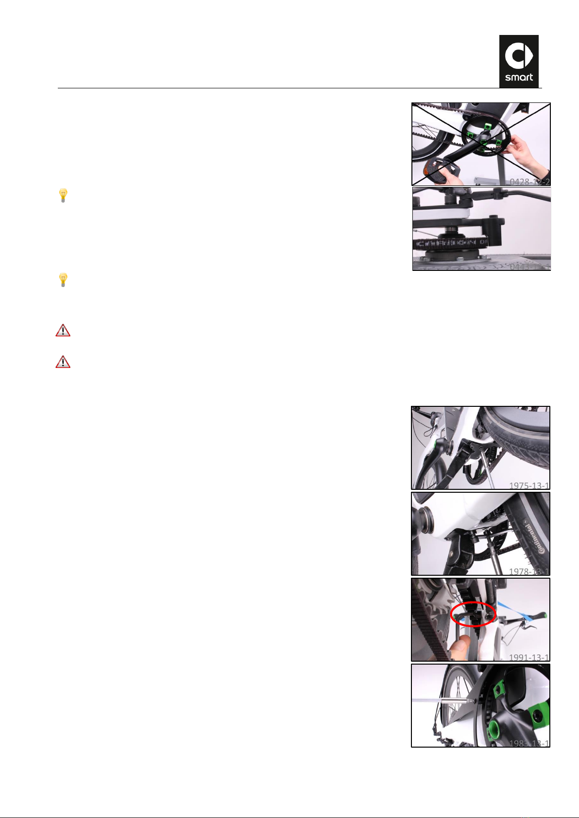
The following movements must be avoided at all costs when handling the drive belt:
Kinking it
Twisting it
Bending it against its curvature
Turning it inside out
Lashing or tying it together with a cable tie or cord
Using it as a wrench
Installing the drive belt under tension with a lever
RL39 - Repair instructions for changing the frame
Version 1.0, last revised 03/2016
4/58
Installing the drive belt under tension by turning the crankset
To rule out the possibility of the belt skipping on the rear belt pulley, a guide
is installed on the dropout of your smart ebike. This ensures that the belt
always remains meshed with the belt pulley. The guide can be moved in the
slot in the right dropout after slackening the mounting bolt. In normal
operation, the distance between the belt and the guide is 1 – 1.5 mm. The bolt
is tightened with a size 5 Allen wrench and a torque of 6 Nm.
The disc brakes installed on the smart ebike use a low-viscosity mineral oil as brake fluid which, compared to DOT
brake fluid (as used in cars, motorcycles and other disc brakes for bicycles) is not irritant towards skin and eyes.
And in contrast to DOT brake fluid, this mineral oil is not hygroscopic. Therefore it does not tend to absorb moisture
from the environment which would reduce its boiling temperature. The brake fluid can thus be used for many years
as long as the brake system is leaktight and correctly filled.
When filling the disc brake system on your smart ebike, you should only use the mineral oil offered by the brake
manufacturer (“Magura Royal Blood”). Oils from other manufacturers and DOT brake fluid could cause damage to
the seals and lead to failure of the brakes.
Brakes which have been filled even once with the wrong medium, i.e. with DOT brake fluid, cannot be repaired. They
must be replaced completely.
A. Removing the belt guard (only on models with belt guard)
1.
Undo the two rear bolts of the kickstand plate using a size 5 Allen wrench.
2.
Undo the bolt on the mounting bracket of the belt guard on the rear stay using
a T25 angled Torx wrench.
3. L
Undo the bolt on the battery nest using a T25 Torx wrench.
RL39 - Repair instructions for changing the frame
Version 1.0, last revised 03/2016
5/58
B. Reducing the belt tension
In order to allow the belt to be removed from the belt pulleys without tension, the distance between the spindle of
the bottom bracket and the rear axle must be reduced. To do this, use the horizontally adjustable dropouts of the
ebike.
4.
Undo the bolts at the dropouts on both sides of the ebike using a size 6 Allen
wrench (2 bolts on the right, 3 bolts on the left).
5.
First undo the nuts for axial adjustment on both sides of the ebike using a size
10 open end wrench while countering the adjusting bolt with the second size
10 open end wrench. Then loosen the adjusting bolt too.
6.
Push the dropouts towards the front in the slot of the frame. To do this, pull the
rear wheel towards the front while bracing yourself against the frame with
your other hand.
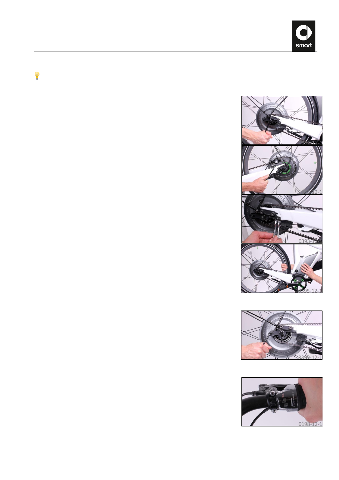
C. Removing the belt guide
7.
Undo the bolt of the belt guide at the right dropout using a size 5 Allen wrench
and remove it.
D. Removing the rear wheel
8.
Turn the twist grip to 1st gear.

RL39 - Repair instructions for changing the frame
Version 1.0, last revised 03/2016
6/58
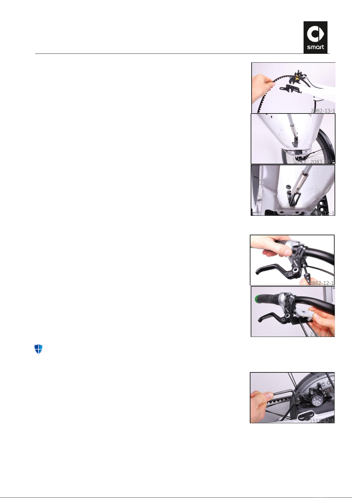
9.
Separate the connection between the shift cable and the rear wheel hub on the
right chain stay by pressing the tab on the locating sleeve and pulling the
sleeve off the threaded element.
CAUTION: When REMOVING the rear wheel, separate the communication
connector first, and then the power connector!
10.
Cut the end cap off the shift cable using side cutting pliers.
11.
Loosen the grub screw using a size 2.5 Allen wrench so that the shift cable can
be pulled out of the plastic sleeve.
12.
Disconnect the data cable (round connector) on the left chain stay from the
motor. To undo the catch of the connector, push the plastic sleeve on the jack
in the opposite direction to the printed arrow.
13.
Disconnect the power cable (flat, oval connector) on the left chain stay from the
motor and release both cables from the cable guide.

RL39 - Repair instructions for changing the frame
Version 1.0, last revised 03/2016
7/58
14.
Carefully press the belt off the rear belt pulley first, and then off the front belt
pulley.
Alternatively, push the lower span of the belt carefully towards the ebike so that it runs off the front belt pulley
when the crank is turned backwards.
Always observe the notes on handling the belt at the beginning of this repair guide.
In the next step, hold onto the rear wheel firmly so that it does not accidentally fall out of the frame.
15.
Undo the nuts on the rear wheel axle using a size 15 open end wrench. The rear
wheel can now be removed downwards from the dropouts.
16.
Push the transport lock between the brake pads.

RL39 - Repair instructions for changing the frame
Version 1.0, last revised 03/2016
8/58
E. Removing the cable outlets
17.
Undo the bolts of the cable outlet on the right side of the downtube using a T25
Torx wrench and detach the cable outlet.
18.
Undo the bolts of the cable outlet on the right rear stay using a T25 angled Torx
wrench and detach the cable outlet.
Repair instructions “Replacing rear brake”: Loosen the rear bolt of the cable
outlet on the left rear stay using a T25 angled Torx wrench (approx. 3 turns). It
is not necessary to remove it completely!
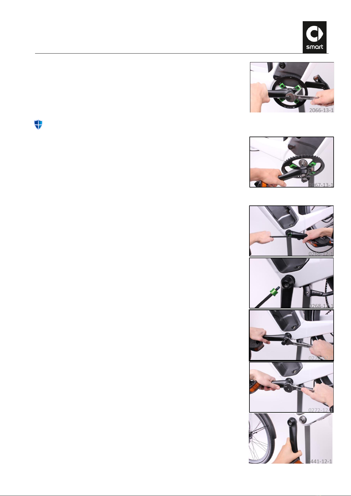
F. Removing the right crank
19.
Undo the crank bolts using a size 8 Allen wrench and remove the trim sleeve.
20.
Grease the crank thread and screw the crank remover clockwise all the way in
finger-tight. Make sure when doing this that the puller screw is unscrewed as
far as the stop.
RL39 - Repair instructions for changing the frame
Version 1.0, last revised 03/2016
9/58
21.
Remove the crank by turning the puller screw of the crank remover clockwise.
Always observe the notes on handling the belt.
22.
Take the crank off the axle.
G. Removing the left crank
23.
Undo the crank bolts using a size 8 Allen wrench and remove them and the trim
sleeve.
24.
Grease the crank thread and screw the crank remover clockwise all the way in
finger-tight. Make sure when doing this that the puller screw is unscrewed as
far as the stop.
25.
Remove the crank by turning the puller screw of the crank remover clockwise.
26.
Remove the crank remover and take the crank off the axle.

RL39 - Repair instructions for changing the frame
Version 1.0, last revised 03/2016
10/58
H. Removing the kickstand plate
27.
Undo the four bolts of the kickstand plate using a size 5 Allen wrench and
remove it together with the kickstand.
I. Removing the inner bearing
28.
Carefully pull the rectangular connector out of the frame and unplug the
connector. To do this, press in the locking clip using your fingernail to undo
the catch on the connector.
The inner bearing tool has only a short insertion depth in the bearing shells. When installing/ removing the
bearing shells, always exert an axial pressure on the tool in order to prevent it from slipping and causing damage.
The smart ebike has an inner bearing which can be adjusted in the axial direction by means of spacer rings. This
allows the line of the belt to be corrected. The line of the belt is set correctly at the factory, but it may need to be
adjusted if parts of the drive system have been replaced.
29.
Remove the seals on both sides of the inner bearing from the axle.

RL39 - Repair instructions for changing the frame
Version 1.0, last revised 03/2016
11/58
30.
Fit the inner bearing tool on the internal teeth on the left of the inner bearing
and detach the plastic shell. When doing so, hold the inner bearing tool with
your other hand so that it does not accidentally slip out of the teeth. If
necessary, make a note of the number of spacer rings installed on the bearing
shell.
The right bearing shell of the inner bearing has a groove in which the axle unit engages. To prevent the axle unit
from turning while the right bearing shell is being removed, the shell must be separated from the axle unit using
the inner bearing assembly press.
31.
Fit the inner bearing assembly press on the bottom bracket shell of the frame
and screw the hemisphere against the inner bearing axle until a cracking noise
is heard and the axle unit has detached.
32.
Carefully pull the axle unit out of the left side of the bottom bracket shell while
feeding through the connector of the sensor.
33.
Now remove the right bearing shell (left-hand thread!) and, if necessary, make
a note of the number of spacer rings installed on the bearing shell.

RL39 - Repair instructions for changing the frame
Version 1.0, last revised 03/2016
12/58
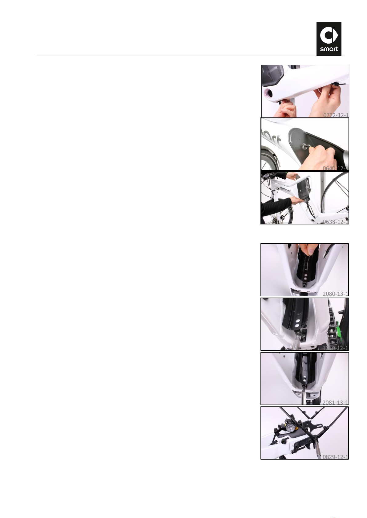
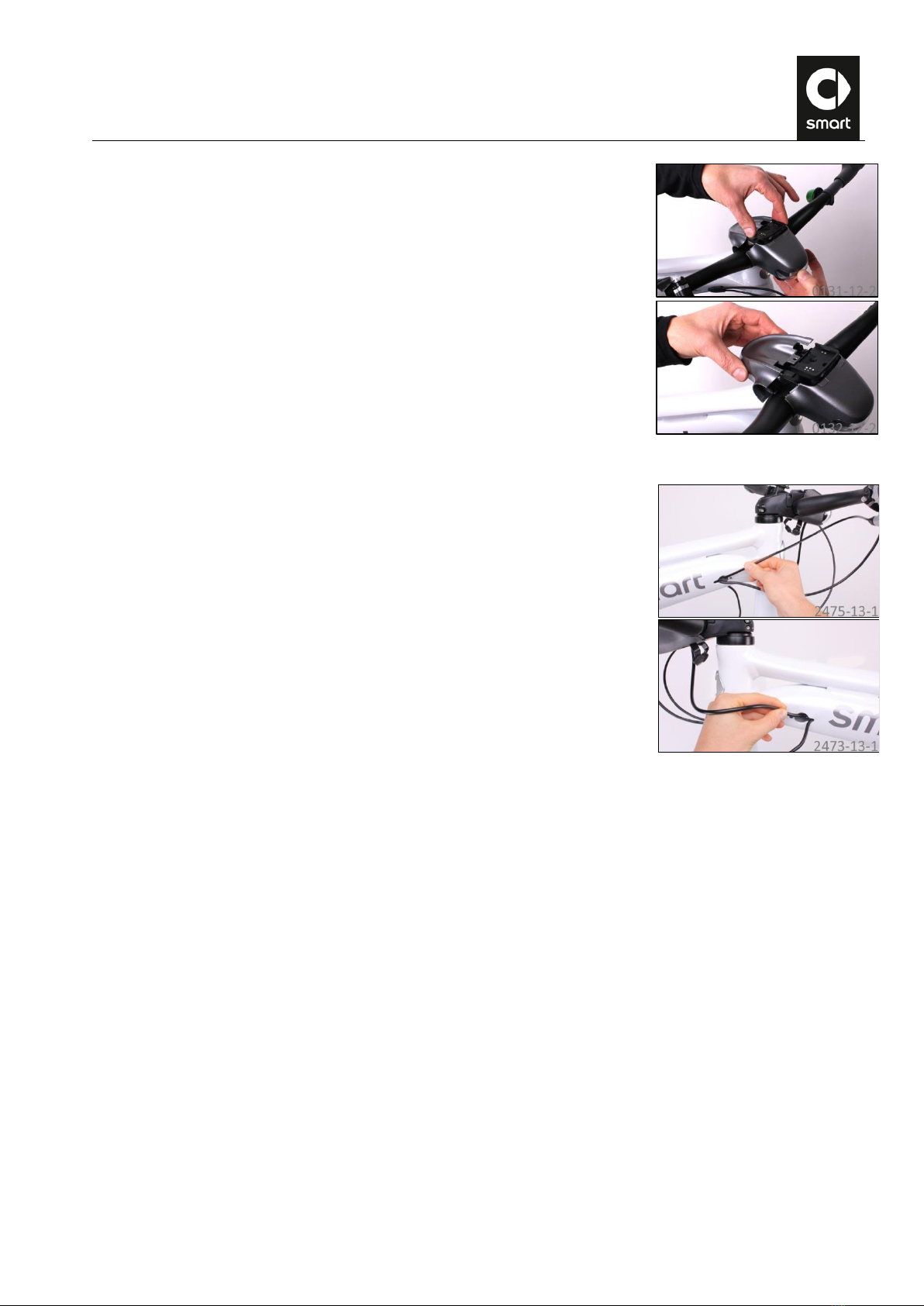
J. Removing the battery nest
34.
Carefully unplug the data cable from the jack underneath the stem assembly.
35.
Pull out the light cable connectors (3MTM ScotchlokTM).
36.
Snip off the two ScotchlokTM connectors flush.
37.
Take a 2.4 mm welding rod and bend it over approx. 20 mm as shown.
38.
Fasten the connector of the front data cable to the welding rod using adhesive
tape.
39.
Grip the front data cable in the bottom bracket and pull and feed it out of the
frame.
40.
Remove the adhesive tape. The welding rod remains in the frame for further
work.
41.
Grip the power cable in the bottom bracket and pull and feed it out of the frame.
RL39 - Repair instructions for changing the frame
Version 1.0, last revised 03/2016
13/58
42.
Grip the rear data cable in the bottom bracket and pull and feed it out of the
frame.
43.
Undo the bolts of the battery nest using a T30 angled Torx wrench and remove
the collared washers.
44.
Pull the battery nest upwards towards the right side out of the frame with the
cable set.
K. Removing the rear mudguard
45.
Pull the light cable out of the hole in the mudguard.
46.
Undo the bolt connecting the mudguard to the frame with a T25 Torx wrench.
47.
Undo the bolts connecting the mudguard stays on the left and right dropouts
with a T30 Torx wrench.
RL39 - Repair instructions for changing the frame
Version 1.0, last revised 03/2016
14/58
48.
Take the belt off the frame.
49.
Undo the two bolts on the frame with a T25 Torx wrench and remove the
mudguard connection from the frame.
L. Removing the right brake line
50.
Push the protective cap on the line connection of the right brake lever a few
centimeters along the brake line.
51.
Use the cable cutter to snip off the brake line of the old brake at the brake lever.
In doing so, shorten the brake line as little as necessary.
Do not pull the brake lever while the brake system is open.
M. Removing the rear brake caliper
52.
Undo the brake caliper retaining bolts using a size 5 Allen wrench and remove
the brake caliper.

RL39 - Repair instructions for changing the frame
Version 1.0, last revised 03/2016
15/58
53.
Carefully pull the brake line out of the frame.
The brake line of the rear brake should measure 1470 mm when installed on the
smart ebike. As it is necessary to cut the brake line in order to route it inside
the frame, it is delivered with surplus length. Measure the length of the brake
line in its original condition and make a note of how much it will have to be
shortened by after routing so as to have a total length of 1470 mm.
N. Removing the dropouts
54.
Loosen the bolts at the dropouts on both sides of the ebike using a size 6 Allen
wrench (2 bolts on the right, 3 bolts on the left) and remove the dropouts.
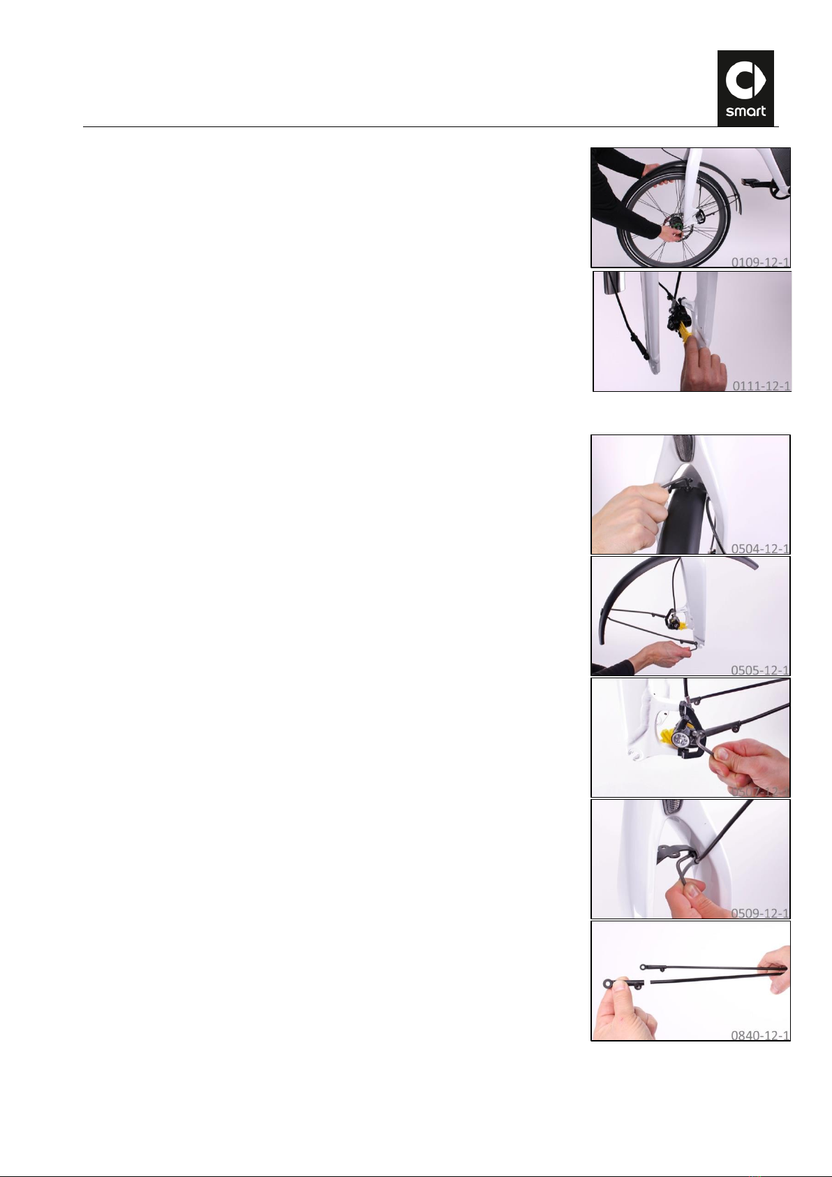
O. Removing the front wheel
The axle on the front wheel of the smart ebike is fitted with a quick-release
system for rapid assembly and disassembly. The quick-release clamp basically
consists of two elements:
The hand lever on one side. This uses a cam to convert the closing action
into a clamping force.
The nut on the opposite side. This is used to adjust the preload.
To open the connection, the hand lever is moved away from the wheel and then
the nut on the opposite side is unfastened counterclockwise. To close, the
preload is adjusted with the nut and the connection is clamped by flipping the
hand lever through 180°. The hand lever is moved from the OPEN position to the
closed position. The lettering CLOSE should now be readable. The preload
should start to act when the hand lever is in line with the hub axle. A adequate
preload is obtained when it is so difficult to close the quick-release clamp that
you need to make a fist in order to flip the clamping lever.
A restrainer on the fork of the smart ebike prevents the front wheel from falling out accidentally when the quick-
release lever is opened. To remove the wheel, also slacken the nut on the opposite side from the quick-release lever.
RL39 - Repair instructions for changing the frame
Version 1.0, last revised 03/2016
16/58
55.
Open the quick-release lever and remove the front wheel from the fork.
56.
Push the transport lock between the brake pads.
P. Removing the front mudguard
57.
Remove the mudguard and the mudguard bracket from the fork with the aid of
a T25 angled Torx wrench and a size 8 open end wrench.
58.
Only when converting from a rigid fork to a suspension fork:
Remove the mudguard stay adapters from the mudguard stays. To do this, undo
the bolts using a T20 Torx wrench.

RL39 - Repair instructions for changing the frame
Version 1.0, last revised 03/2016
17/58
Q. Removing the front brake caliper
59.
Pull the brake line guide off the brake line. (Also when converting from a rigid
fork to a suspension fork!)
CAUTION: When replacing a suspension fork: Cut the cable tie on the fork bridge
using side cutting pliers.
60.
Undo the brake caliper retaining bolts using a size 5 Allen wrench and remove
the brake caliper.
Return the removed rigid fork to the customer in case it is reinstalled at a later
date. You can use the original box of the suspension fork for this purpose.
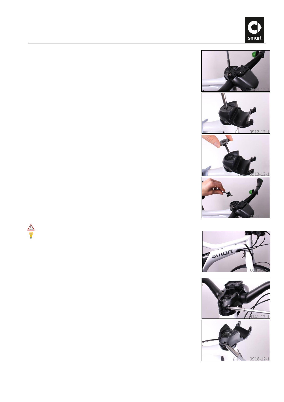
R. Removing the stem trim
61.
Remove the control console from its cradle.
62.
Unplug the connector of the brake sensor cable from the jack underneath the
stem assembly.
63.
Carefully unplug the data cable from the jack in the control console cradle.
64.
Unscrew the bolt in the control console cradle using a T20 Torx wrench.
RL39 - Repair instructions for changing the frame
Version 1.0, last revised 03/2016
18/58
S. Removing the stem
67.
When replacing the frame/fork: Pull the Bowden cable with its sheath out of the
frame.
68.
Pull the light cable out of the frame.
65.
Carefully push the control console cradle approx. 1 cm upwards out of the
housing by pressing carefully from below between the cable jacks while
simultaneously pulling up on the control console cradle.
66.
Pull the plastic cover off the stem towards the rear.
RL39 - Repair instructions for changing the frame
Version 1.0, last revised 03/2016
19/58
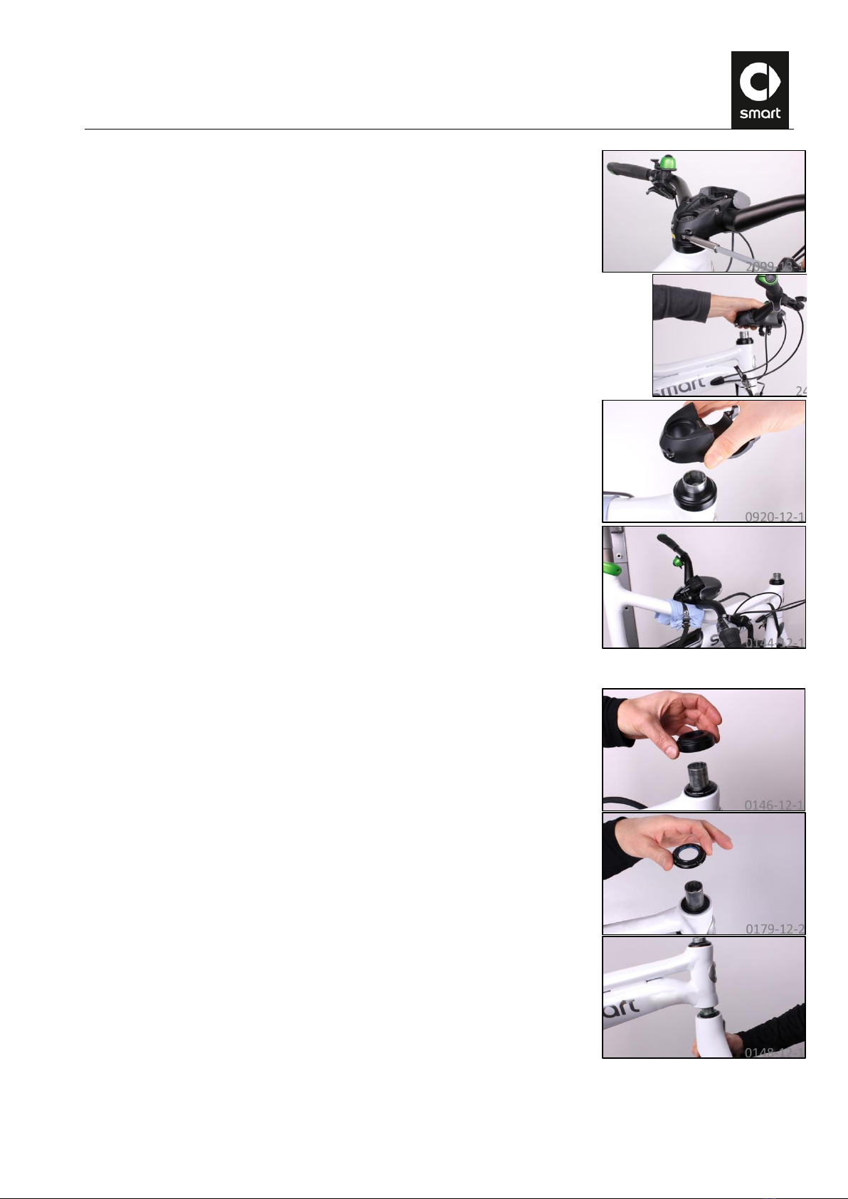
69.
Undo the threaded connection of the A-head cap using a size 5 Allen wrench
and remove the A-head cap.
In the next step, the fork can fall down out of the head tube.
Secure the fork with a tensioning strap or a cable tie to prevent it from falling.
70.
Hold the fork securely while loosening the stem clamping bolts with a size 5
Allen wrench.
RL39 - Repair instructions for changing the frame
Version 1.0, last revised 03/2016
20/58
71.
Pull the handlebar/stem assembly upwards off the steerer tube. Make sure that
you do not damage the light cable.
72.
73.
Fasten the handlebar/stem assembly to the frame. For this, use a tensioning
strap for example. Protect the paintwork with a cleaning cloth.
Removing the fork
74.
Remove the spacer ring from the steerer tube.
75.
Remove the sealing ring from the steerer tube.
76.
Carefully pull the fork downwards out of the head tube.
Table of contents
Other Bion X Bicycle manuals


