Bion X Bicycle User manual

USER MANUAL
GUIDE D’UTILISATION
BENUTZERINFORMATION

2
english

3
Welcome
Thank you for choosing BionX™. It is our goal to provide you with the highest quality electric
propulsion systems available, and offer you the best possible after sales experience.
This document serves as a supplement to your bicycle user manual. Please read this manual
thoroughly, even if you are an experienced cyclist. Should you be unable to find an answer in
the manual, please contact your dealer for immediate assistance.
We have always believed that a bike should remain a bike. It is our love of cycling that drives
us, and a passion that we continue to share with our customers. We hope you enjoy your
new electrically assisted bicycle for many years to come.
If you ever have concerns or questions that your dealer cannot provide
answers to, or have comments relating to this user manual, feel free to contact
[email protected], and anywhere else in the world at
english

4
User Precautions
We want you to have a fun ride, but also a safe one. Carefully read the following information,
even if you are an experienced rider. Take the opportunity to familiarize yourself with your
BionX electric propulsion system before you take your first trip.
1. BionX recommends that you have your system installed professionally by an authorized dealer.
2. Read all of the enclosed installation and operating instructions from the manufacturer
and follow the instructions, if any, prior to its first use.
3. Familiarize yourself with your electric bicycle and the functions of the BionX system in a safe
environment before participating in road traffic for the first time.
4. Always wear a helmet when riding an electric bicycle for your own safety. In some jurisdictions,
this is the law.
5. Make sure that the tires have the pressure recommended by the manufacturer before riding the bike.
6. Make sure that the brakes are operating properly before riding the bike.
7. Do not use a mobile phone or any other electronic devices while riding an electric bicycle; it is
imperative that you pay attention to traffic.
8. If possible, ride in bike lanes and always in the correct direction of traffic.
9. Adhere to all valid traffic regulations.
10. Keep in mind that other traffic participants may underestimate the speed of an electric bicycle.
11. Ride with both hands on the handlebars when riding your electric bicycle.
12. Ride as defensively as possible.
Enjoy your new BionX electric propulsion system!
Your BionX Team
english

5
Table of Contents
User Precautions 4
Description of the BionX SL Propulsion System 6
Description of the BionX PL Propulsion System 8
Inserting or Removing the Console 10
Inserting or Removing the Battery 11
Handling and Charging the Battery 12
Power supply 14
Chargers 15
Assist Mode / Generate Mode /
Mountain Mode (where applicable) 16
Operating the BionX Propulsion System 17
Operating the G2 throttle 19
Programming the Basic Settings 20
Removing and Installing the Rear Wheel 21
Maintenance and Care 22
Cleaning 23
Transporting an Electric Bicycle 23
Repair and Spare Parts 23
Troubleshooting 24
Warranty Information and Guarantee 25
english

6
4
2a
1
3
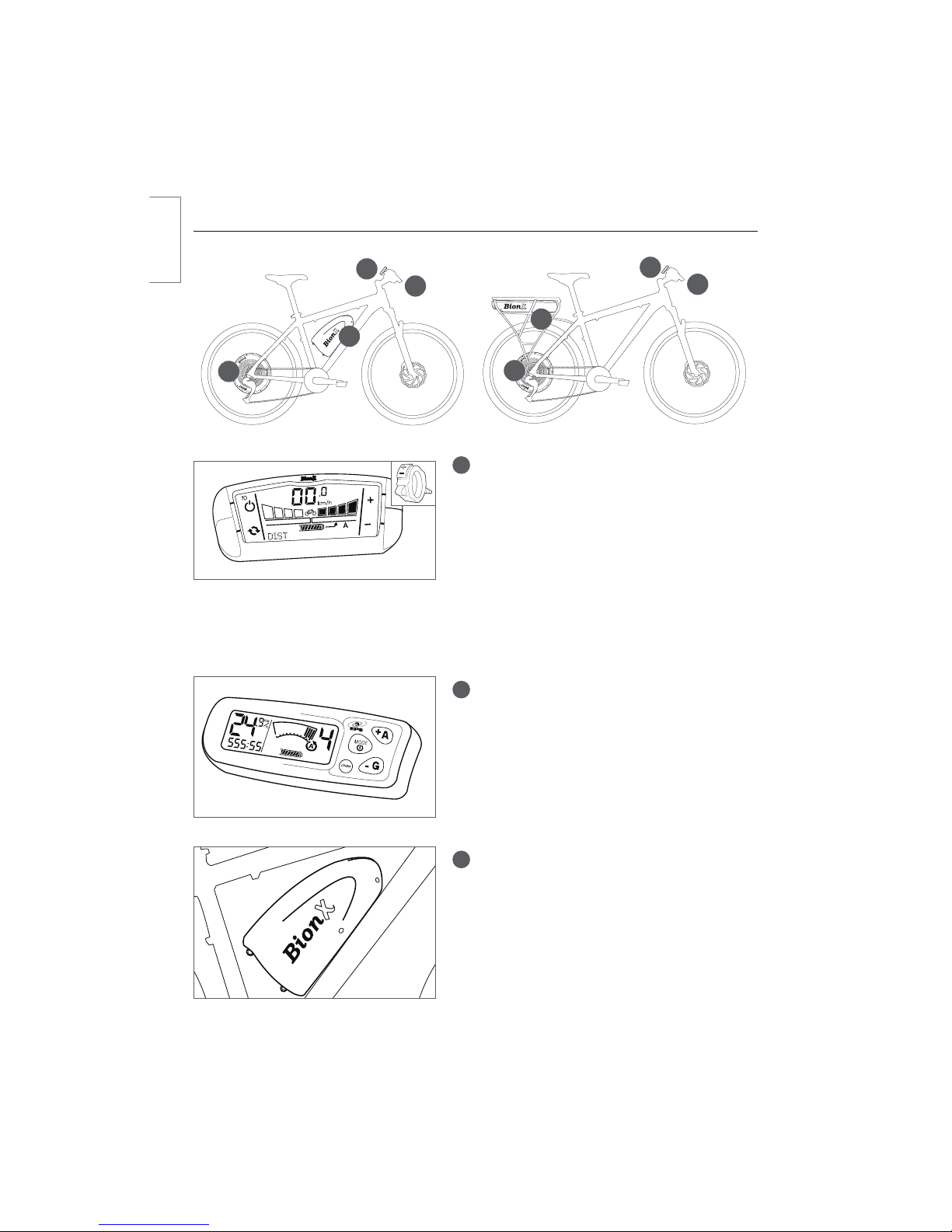
Description of the BionX SL Propulsion System
1G2 Console
tRemovable G2 console
tIlluminated LCD display with battery state-of-charge
t"TTJTUBODFMFWFMTt(FOFSBUFMFWFMTt#BDLMJHIUBOECJDZDMFMJHIUDPOUSPMTJGBQQMJDBCMFt0GGFSTDZDMFDPNQVUFSGVODUJPOTTQFFEPEPNFUFSDMPDLBWFSBHFTQFFEUSJQEJTUBODFRemote throttle (where applicable)
t"TTJTUBODF(FOFSBUF5PHHMFt7BSJBCMFDPOUSPMUISPUUMFMFWFS2a 48V Down Tube Battery
t-JUIJVN*PO-J*POtRemovable, lockable
t506$)1035TUBUFPGDIBSHFJOEJDBUPSt9-o7"I8It-o7"I8IXIFSFBWBJMBCMFt%$0VUQVU%FGBVMU7BEKVTUBCMFGSPN7UP7XIFSFBQQMJDBCMF.BYJNVNDVSSFOUBNQT
$POOFDUPS5ZQF+BDLNN2b 48V Rear Rack Battery
t-JUIJVN*PO-J*POtRemovable, lockable
t506$)1035TUBUFPGDIBSHFJOEJDBUPSt339-7"I8It33-7"I8IXIFSFBWBJMBCMFt%$0VUQVU%FGBVMU7BEKVTUBCMFGSPN7UP7XIFSFBQQMJDBCMF.BYJNVNDVSSFOUBNQT
$POOFDUPS5ZQF+BDLNN2b
3
1
4
english

7
3SL Motor
t%$SFBSIJHIUPSRVF)5IVCNPUPSt1PXFSo8"66,8&68/"t5PSRVFo/N/NMCGUt8FJHIUoLHMCtBrushless, gearless
tGenerate mode for energy recuperation
tIntegrated torque sensor
4Brake switch
tA surface mounted reed switch and magnet –
connected to the BionX console
t6QPOCSBLFBQQMJDBUJPOBTTJTUBODFJTTIVUPGG
iLJMMTXJUDIwBOE(FOFSBUFNPEFJTBDUJWBUFEPower Supply
t1PXFSTVQQMZUPSFDIBSHFUIF7-J*POCBUUFSZt*OQVUWPMUBHF7t0VUQVUWPMUBHF7t.BYDIBSHFDVSSFOU"t0VUQVU8
english
8
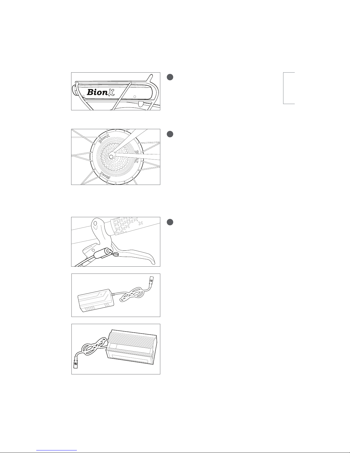
Description of the BionX PL Propulsion System
1G2 Console (systems 2011 to present)
tRemovable G2 console
tIlluminated LCD display with battery state-of-charge
t"TTJTUBODFMFWFMTt(FOFSBUFMFWFMTt#BDLMJHIUBOECJDZDMFMJHIUDPOUSPMTJGBQQMJDBCMFt0GGFSTDZDMFDPNQVUFSGVODUJPOTTQFFEPEPNFUFSDMPDLBWFSBHFTQFFEUSJQEJTUBODFRemote throttle (where applicable)
t"TTJTUBODF(FOFSBUF5PHHMFt7BSJBCMFDPOUSPMUISPUUMFMFWFS1G1 Console (systems 2010 and earlier)
t(DPOTPMFPQUJPOBMUISPUUMFMFWFSXIFSFBQQMJDBCMFtIlluminated LCD display with battery state-of-charge
t"TTJTUBODFMFWFMTt(FOFSBUFMFWFMTt#BDLMJHIUBOECJDZDMFMJHIUDPOUSPMTJGBQQMJDBCMFt0GGFSTDZDMFDPNQVUFSGVODUJPOTTQFFEPEPNFUFSDMPDLBWFSBHFTQFFEUSJQEJTUBODF2a 22, 26 or 37V Down Tube Battery
t-JUIJVN*PO-J*POtRemovable, lockable
t-7"I8It.7"I8It47"I8I4
2a
1
3
2b
3
1
4
ODO
english
9
2b 37V Rear Rack Battery
t-JUIJVN*PO-J*POtRemovable, lockable
t33-7"I8It33.7"I8It%$0VUQVU%FGBVMU7BEKVTUBCMFGSPN7UP7XIFSFBQQMJDBCMF.BYJNVNDVSSFOUBNQT
$POOFDUPS5ZQF+BDLNN
3250, 250HT, 350HT, or 500HS* Motor
tDC rear hub motor
tOPNPVUQVU"66,PSXBUUo
OPN/NNBY/NMCGUUPSRVFt)5)5OPNPVUQVU"66,
&6/"XBUUToOPN/NNBY/N
MCGUUPSRVFtOPNXBUUoOPN/NNBY/NMCGUUPSRVFt8FJHIULHMCtBrushless, gearless
tGenerate mode for energy recuperation
tIntegrated torque sensor
4Brake switch
tA surface mounted reed switch and magnet –
connected to the BionX console
t6QPOCSBLFBQQMJDBUJPOBTTJTUBODFJTTIVUPGG
iLJMMTXJUDIwBOE(FOFSBUFNPEFJTBDUJWBUFE37V Single LED Battery Charger
(PL systems 2011 to present)
t5PSFDIBSHFUIF7-J*POCBUUFSZt*OQVUWPMUBHF7t0VUQVUWPMUBHF7t.BYDIBSHFDVSSFOU"22V, 26V or 37V Two LED Battery Charger
(PL systems 2011 and earlier)
t5PSFDIBSHFUIF77PS7-J*POCBUUFSZt*OQVUWPMUBHFTXJUDIBCMFCFUXFFO7t0VUQVUWPMUBHF77PS7EFQFOEJOH
upon model
t.BYDIBSHFDVSSFOU"/PUFUIFXBUUNPUPSJTOPUMFHBMJOBMMKVSJTEJDUJPOT$IFDLXJUIZPVSMPDBM#JPO9EFBMFSGPSMPDBMMFHJTMBUJPOBOEPSBWBJMBCJMJUZ
english

10
Inserting or Removing the Console
Inserting the console
tSlide the console into the console mount on the handlebar
t.BLFTVSFUIBUUIFDPOTPMFFOHBHFTTFDVSFMZ8IFOJOTFSUFEDPSSFDUMZZPVXJMMIFBSBiDMJDLwRemoving the console
tRelease the console by pushing the release lever on the console mount
tSlide the console out of the console mount
iDMJDLw
english
11
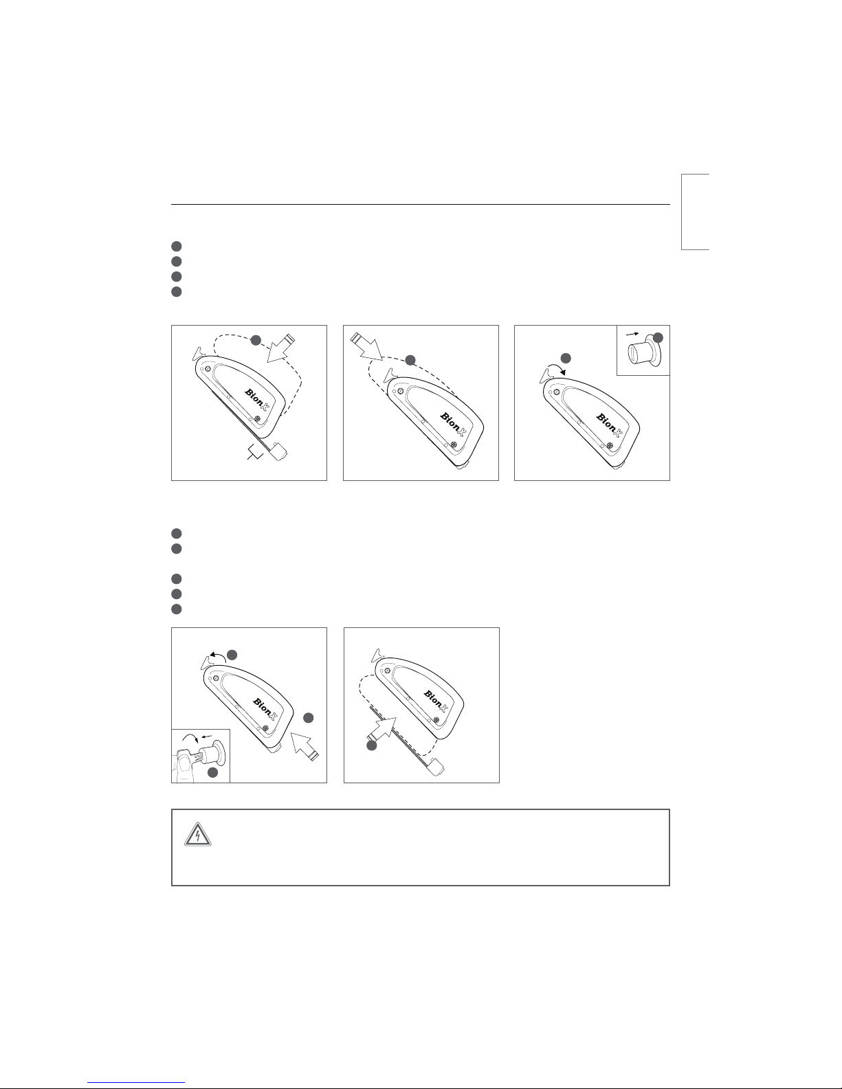
Inserting or Removing the Battery
Inserting the down tube battery
1Place the battery onto the docking station
2Slide the battery down the rail gently towards the connector
3The release arm will begin to move to the closed position as the battery slides towards the connector
4When the release arm is almost closed, hold it in place and simultaneously push in the lock cylinder –
ZPVXJMMIFBSBiDMJDLwXIFOUIFMPDLDZMJOEFSJTQSPQFSMZDMPTFERemoving the down tube battery
15VSOPGGUIF#JPO9QSPQVMTJPOTZTUFNWJBUIFDPOTPMFOPJMMVTUSBUJPO2Lightly press on the battery release arm, insert the key and turn clockwise
The lock cylinder will pop out, freeing the battery release arm
3Remove the battery by opening the release arm
4Slide the battery upwards on the rail
5Lift the battery to remove
001
001
2
3
4
5
WARNING
Do not force the battery release arm closed, or force the battery onto the battery dock.
This can damage the battery connector.
1” (25.4mm)
1
23
iDMJDLw
4
english
12
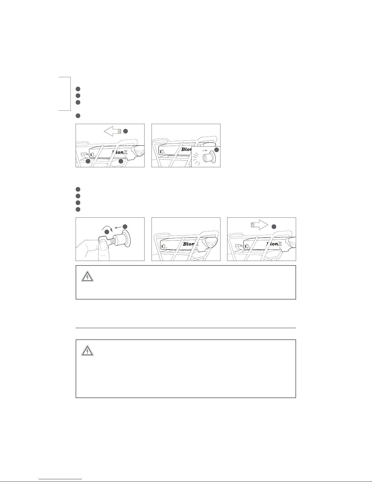
Inserting the rear rack battery:
10QFOUIFMPDLDZMJOEFSQMFBTFFOTVSFUIBUUIFLFZJTSFNPWFEGSPNUIFMPDLDZMJOEFS2Place the battery onto the battery docking station
3Gently push the battery in a forward direction, towards the battery connector
Make sure the battery is inserted all the way, flush with the docking station cover
4Push in the lock cylinder until a ‘click’ is heard
Removing of the rear rack battery:
15VSOPGGUIFTZTUFNWJBUIFDPOTPMFOPJMMVTUSBUJPO2Turn the key in the lock cylinder until it pops out
3Remove the key from the lock cylinder
4Pull the battery backwards, along the battery rail
Handling and Charging the Battery
WARNING
BionX batteries shall only be recharged with BionX chargers or BionX power supplies.
Never short circuit the battery by connecting the contacts of the battery. Never open
the battery, as this could damage the battery and possibly lead to overheating. The
battery cannot be serviced by the user. Opening the battery case voids all warranty and
product liability claims. Never use a battery which has obvious damage to the case(s) or
the battery connector.
001
001
2
3 4
WARNING
Do not force the battery onto the battery docking station. This can damage the battery
connector, or damage the rear light.
CLICK
1 2
3
4
english
13
Make sure that the battery is no longer connected to the power supply or charger once the charging
operation is complete. The Lithium Ion battery cells have a low self-discharge rate, therefore a continuous
connection of the battery to the power supply or charger is not necessary. We recommend that you fully
charge the battery when it will not be used for a longer period of time, for example, before storing it for
the winter, and then recharge the battery at minimum every three months.
*UJTCFTUUPTUPSFUIFCBUUFSZJOBDPPMMPDBUJPOBUUFNQFSBUVSFTCFUXFFO¡$¡'BOE¡$¡'/FWFSTUPSFUIFCBUUFSZJOMPDBUJPOTXIFSFUIFUFNQFSBUVSFTDBOSFBDINPSFUIBO¡$¡'PS
GBMMCFMPX¡$¡'5IFCBUUFSZTIPVMEOFWFSCFFYQPTFEUPFYUSFNFUFNQFSBUVSFnVDUVBUJPOT
or humidity, and always protect the battery during storage from humidity to prevent corrosion of the
connectors. Never drop the battery. Always protect it from physical damage. Damage may lead to short-
circuits, and as a result cause overheating of the battery.
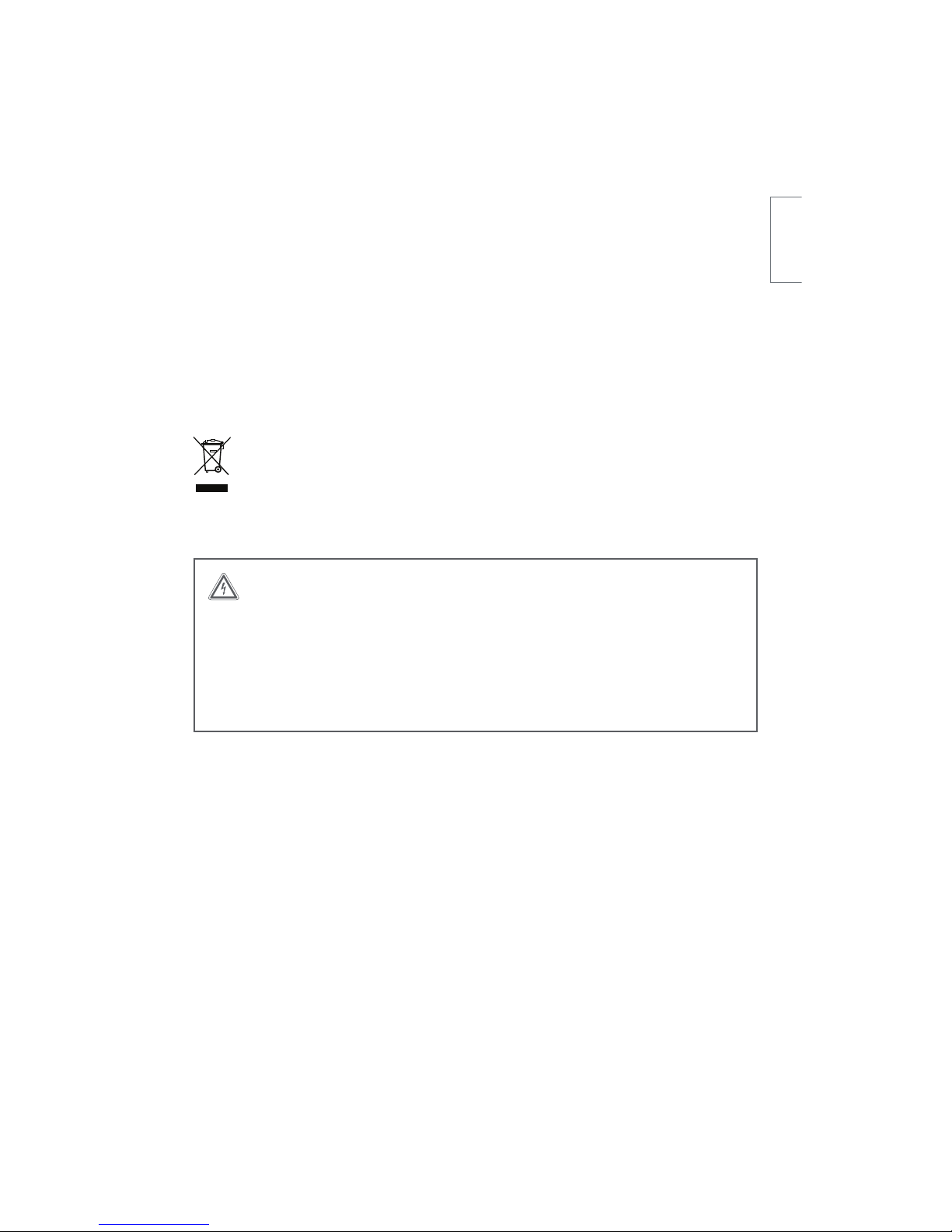
Do not dispose of used batteries in regular household trash!
Be aware that used batteries must be disposed of properly!
BionX batteries can be returned to BionX to be recycled.
Charging the battery:
WARNING
Only use the BionX power supply or charger that was supplied with the system to charge
the battery. The use of other power supplies/chargers can damage the battery.
The BionX power supply/charger should be used exclusively for BionX rechargeable
batteries of the specified type. Keep the power supply or charger away from water or
moisture when charging and/or connected to prevent electrical shock or short-circuits.
Do not use a power supply or charger that has obvious signs of damage to the cable,
housing, or the connector.
Extreme temperatures will affect battery life, especially during charging. Avoid charging in direct sunlight
or in very hot or cold temperatures. This will reduce the life of the battery considerably. We recommend
DIBSHJOHUIFCBUUFSZBUSPPNUFNQFSBUVSFBQQSPYJNBUFMZ¡$¡'5IFCBUUFSZTIPVMECFXBSNFEUProom temperature before it is charged, particularly if it was exposed to cold temperatures during a ride.
The battery can be charged when mounted on the bicycle or removed from the docking station.
A Lithium Ion battery does not have a memory effect, which means that the battery’s maximum energy
capacity is not affected if it is repeatedly recharged after only being partially discharged. The battery does
not need to be completely drained before charging. We recommend charging the battery after every ride,
preferrably when the state-of-charge display shows less than 50%. We recommend that you fully charge
the battery when it will not be used for a longer period of time, for example, before storing it for
the winter, and then recharge the battery at minimum every three months. When the battery is de-
pleted to the level where there is risk it could fall into deep discharge, the battery will signal that a recharge
is needed by beeping. The battery is fully charged after approximately 4 to 5.5 hours.
english
14
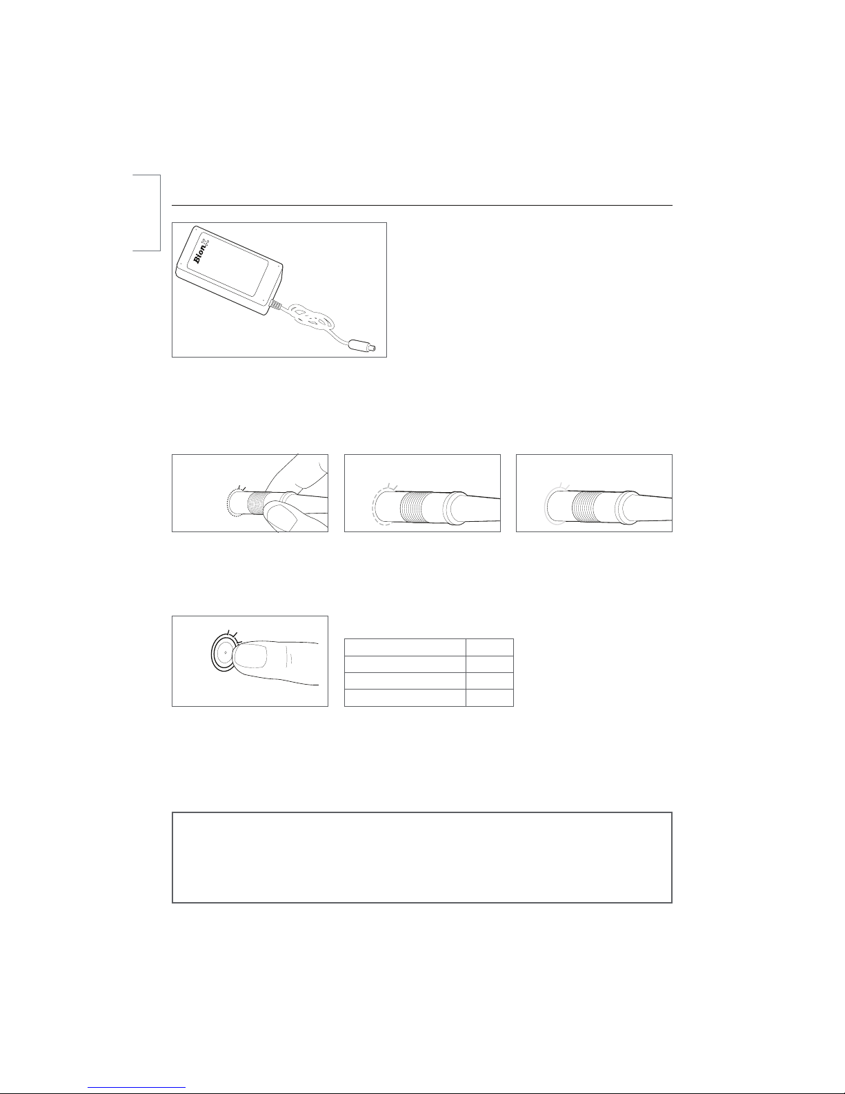
Power supply
SL system charging procedure (power supply)
tConnect the power supply and the battery by
JOTFSUJOHUIFDIBSHFDPOOFDUPSJOUPUIF506$)1035– the BionX system can be on or off
tConnect the power supply to a power receptacle
t5IFCBUUFSZ506$)1035-&%SJOHBSPVOEUIFDIBSHFDPOOFDUPSMJHIUTVQSFEVQPOJOTFSUJPOBOEthen turns to amber during the charging process
tWhen fully charged, the colour of the LED ring
changes to green. The battery charging process is
then complete
tFollowing this procedure the charging connector should be disconnected from the battery
tDuring the charging process you can check the battery state-of-charge through the console if the
CBUUFSZJTDPOOFDUFEUPUIFTZTUFNoB7TZTUFNDBOCFTXJUDIFEPOXIJMFJUJTDIBSHJOH
Battery state-of-charge Colour
100-75 % Green
75-20 % Amber
< 20 % Red
Checking the 48V Battery state-of-charge
t4XJQFZPVSmOHFSTMPXMZPWFSUIF506$)1035tBattery state-of-charge LED will illuminate
t"MMPXUFOTFDPOETCFGPSFDIFDLJOHTUBUFPGDIBSHFBHBJONOTE
The power supply is suitable for line voltage ranges of 110-115V or 220-230V, and com-
pensates automatically. The 48V battery is designed to be charged by a 26V BionX power
supply. The battery has an integrated charger which permits the use of a small, portable
power supply.
Ensure that a completely charged battery is no longer connected to the power supply after the charge
procedure is completed. 506$)1035HSFFO
fully charged
506$)1035BNCFScharging
506$)1035SFE
upon insertion
english
15
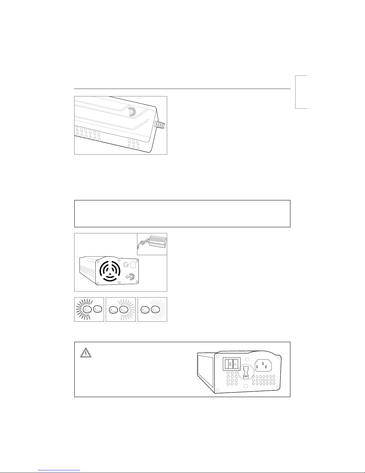
PL-250HT / PL-350HT / PL-500HS
systems charging
procedure, systems 2011 to present (single LED
charger)
tConnect the charger and battery by inserting the
charge connector into the charge port. The BionX
system should be turned off
tConnect the charger to a power receptacle
tThe light on the charger will turn red automatically
tThe same light will then turn yellow to indicate
charging
tThe light will turn green when the battery is fully
charged and the charging process is complete
tFollowing this procedure, the charger should be
disconnected from the battery
PL systems 22V, 26V, 37V charging procedure,
systems 2011 and earlier (two LED charger)
tConnect the charger and battery by inserting the
charge connector into the charge port. The BionX
system should be turned off
tConnect the charger to a power receptacle
tThe power switch must be set to ‘on’ and the red
LED will illuminate
tThe LED to the right of the red LED will illuminate
yellow to indicate charging
tWhen the right LED turns green the battery is fully
charged and the charging process is complete
tFollowing this procedure, the charger should be
disconnected from the battery
WARNING
Check input voltage when travelling with
the two LED charger. Failure to adjust the
voltage switch on a two LED charger to
the correct voltage range can result in
damage to the charger.
115
This notch is very important
NOTE
The 37V single LED charger is suitable for line voltage ranges of 110-115V or 220-230V,
and compensates automatically.
FUSE
-FGU-&%
red, charger on 3JHIU-&%
yellow, charging 3JHIU-&%
green, fully charged
FUSE
-FGU-&%
red, charger on 3JHIU-&%
yellow, charging 3JHIU-&%
green, fully charged
Chargers
english

16
Assist Mode / Generate Mode / Mountain Mode (where applicable)
The BionX propulsion system offers four levels of assist in the Assistance mode, and four levels of
regeneration in the Generate mode. In the Assistance mode, your pedaling is assisted proportionally by
an electric motor that drives the rear wheel. A torque sensor is located on the axle of the BionX motor
and measures the effort provided by the rider; this produces a natural feeling assistance from the motor.
A cadence of roughly 80 RPM is ideal, this allows for effective response from the torque sensor and
efficient use of battery energy.
When in Generate mode, the BionX motor functions as a generator and recharges the battery. When
going downhill, you can regulate your speed by varying the Generate level. This Generate function
provides a level of braking, however it does not replace legally required brakes. If the rear brake lever is
pulled, the drive system automatically enters Generate mode. The range can therefore be extended up to
15%, depending upon road conditions.
The Mountain mode uses an intelligent algorithm based upon the effort and the assistance level required.
The Mountain mode provides the rider with an assistance level optimized for climbing long steep hills.
Without this mode, the motor can automatically revert to an overheat protection mode thereby dimin-
JTIJOHUIFBTTJTUBODFQSPWJEFE5IF.PVOUBJONPEFDBOCFBDUJWBUFEXIFSFBWBJMBCMFCZZPVSEFBMFSthrough a software update of the system.
NOTE
It is recommended that the BionX system should always be turned ON while riding.
It allows the rider to use the regenerative braking feature, speedometer and odometer
functions. Speeds in excess of 60km/h (37mi/hr) are not recommended.
250HT (EU) / 350HT (NA) Motor performance
Assistance Mode (A) Level of Assist Riding Situation
135% Riding on level ground
275% Slight inclines, head wind
3150% Steep hills, strong head wind
4300% 7FSZTUFFQSPBET250/500 Motor performance
Assistance Mode (A) Level of Assist Riding Situation
125% Riding on level ground
250% Slight inclines, head wind
3100% Steep hills, strong head wind
4200% 7FSZTUFFQSPBETMountain Mode (where available) Long, steep climbs
Generation Mode (G)
1Slight downhill grade, tailwind
2Significant downhill grade, tailwind
3Steep descent
47FSZTUFFQEFTDFOU
english
17
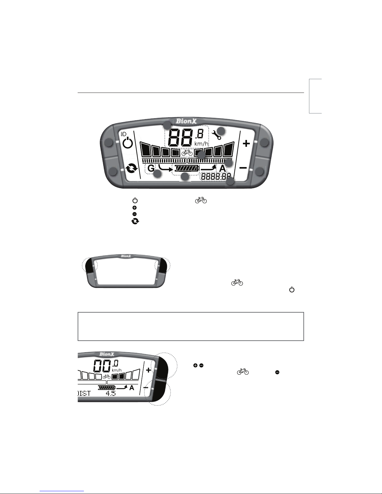
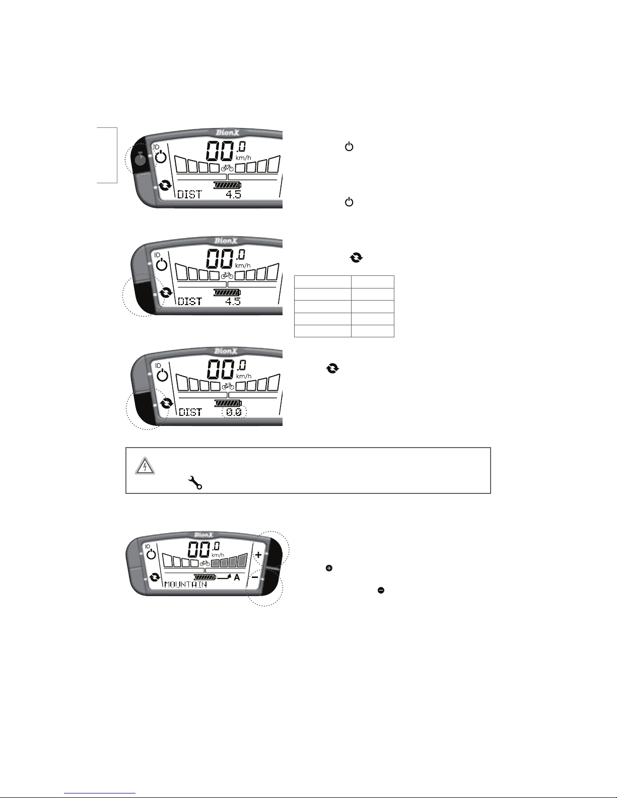
Operating the BionX Propulsion System
Turn the system on
Briefly push either top button on the console. The
battery will beep 4times and you will see a countdown,
this is the system perfoming a self check. After startup,
the system is always in NPEFOPNPUPSBTTJTUCJLFPQFSBUJPO5PUVSOUIFTZTUFNPGGCSJFnZQVTI.
5IFCBUUFSZXJMMCFFQUJNFT"GUFSNJOVUFTPGiOPPQFSBUJPOwUIFTZTUFNUVSOTPGGBVUPNBUJDBMMZSelect Assistance/Generate level
Push LFZGPSNPSFMFTTBTTJTUTFFCBSimFMETwBCPWFEJTQMBZi"w'SPNmode push key to
enter continuous Generate mode.
10
9
21
4 3
7
5
8
6
1. Power
2. Key
3. Key
4. Cycle
5. State-of-charge
indicator
6. CJDZDMFNPEF7. Speedometer
5SJQEJTUBODFBWFSBHFTQFFE
DISPOPNFUFSPEPNFUFSDMPDL"TTJTUMFWFM"(FOFSBUFMFWFM(11. Wrench symbol
G2 Console
NOTE
The system performs a self check approximately every hour. Do not be alarmed if the
system turns itself on briefly, and off again, or if the TOUCH PORT flashes momentarily.
11
english
18
Turn on backlight and bicycle light (if applicable)
Push and hold key for 4 seconds - display backlight
BOECJDZDMFMJHIUJGBWBJMBCMFCBUUFSZJOUFHSBUFEBSFturned on.
Turn off backlight
Push and hold key again for 4 seconds.
Select the cycling computer functions
Briefly push the LFZUPDIBOHFCFUXFFOTrip Distance DIST
0EPNFUFS0%0Clock $-0$,Average Speed "741%Chronometer $)30/0To reset the cycle computer functions
)PMEUIFkey for a few seconds to reset the distance,
chronometer, or average speed values to zero.
4s
WARNING
If this symbol appears please contact your BionX dealer for service.
Mountain Mode (where available)
)PMEUIFCVUUPOGSPNBOZMFWFMPG"PS(UP
FOHBHF5IFGPVSBTTJTUMFWFMTXJMMnBTI.06/5"*/
will appear briefly. Press to disengage.
english

19
Operating the G2 throttle
Throttle engagement:
%FGBVMUNJOLNIUPFOHBHFUISPUUMF/PUFUISPUUMFDPOUSPMJTWBSJBCMFBOEUIFGPSDFgauge on the console reacts proportionally
Assistance levels 1-4:
From press for more assist
or for less assist
Generation 1-4:
From press for more resistance
or for less resistance
NOTE
The G2 throttle is only compatible with the G2 console, and may not be available in all
jurisdictions. Check with your local BionX dealer for local legislation and/or availability.
G1 Console For the G1 console, substitute mode for power, and
crono for cycle. The assistance toggle remains the same.
G1 G2 .PEF1PXFSCFDPNFT1PXFSCrono becomes Cycle
Remains the same
Remains the same
If you require more information on the G1 console,
please contact your dealer.
english
20
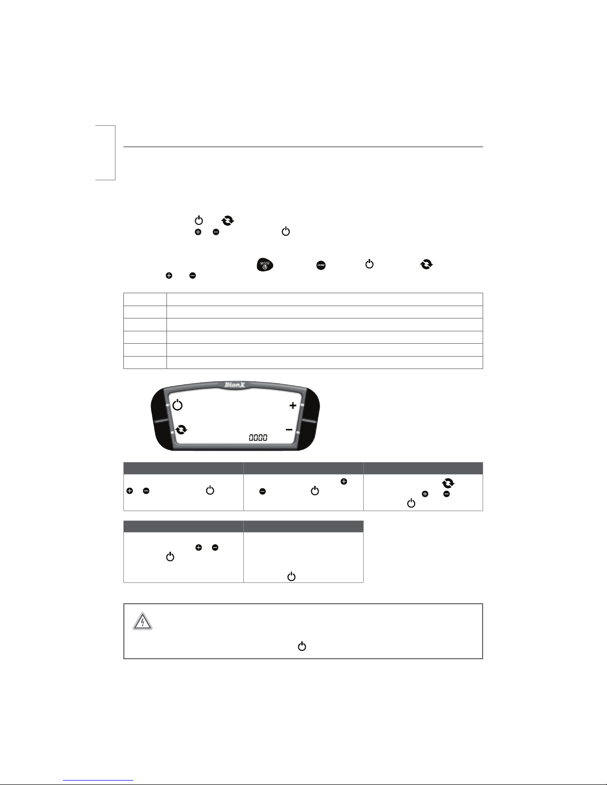
Programming the Basic Settings
In general, all settings of your BionX electric propulsion system are pre-set. Basic display functions can
be set by entering the programming mode. Contact your dealer to customize the advanced functions of
your system.
Turn on the programming mode
Simultaneously push and VOUJMUIFEJTQMBZTIPXTiw5IFmSTU[FSPCMJOLT$IBOHFUIFWBMVFof the selection with or and confirm with . Select the other digits in the same manner until the
desired program is displayed.
Note: For G1 programming, substitute NPEFBOEDSPOPGPSQPXFSBOEDZDMF
respectively, and remain the same.
Code Description
2001 4FMFDULNIPSNQI2002 3FHFOFSBUJPOCSBLFPVUQVUGPSSFFETXJUDIJEFBMMZ2004 Clock adjust
2005 5JSFDJSDVNGFSFODFNJMMJNFUFST2009 'MJQ%JTQMBZQPXFSMFGUQPXFSSJHIU(POMZCode 2001 Code 2002 Code 2004
4FMFDUVOJULNIPSNQI4FMFDUXJUIor , and confirm with . %FGBVMUWBMVF$IBOHFXJUI
and . Confirm with . 4FMFDUIPVSNJOVUFTXJUI,
change value with and .
Confirm with .
Code 2005 Code 2009
4FUUJSFTJ[FJONN4FMFDUEJHJUTone after another with or , and
confirm with .
Current setting of main functions is
EJTQMBZFE'MJQBTTJTUUPHHMFJT
on
UIFSJHIUTJEFPGDPOTPMF'MJQ
assist
toggle is on the left side of console.
Confirm with .
WARNING
Do not use other programming codes without consulting your authorized dealer.
If you type the wrong code, please push the key to exit programming mode.
english
Table of contents
Other Bion X Bicycle manuals


