VENGE VIAS User manual

USER MANUAL


CONTENTS
GENERAL NOTES ABOUT ASSEMBLY....................................................................................... 2
BOLT SIZE / TOOLS / TORQUE SPECS...................................................................................................................................2
GENERAL NOTES ABOUT MAINTENANCE................................................................................. 3
SPARE PARTS............................................................................................................................................................................4
WARRANTY................................................................................................................................................................................4
STEM / STEERER TUBE PARTS ................................................................................................ 5
1. FRAME FIT (ViAS SETUP)..................................................................................................... 7
A. DETERMINING FIT.................................................................................................................................................................7
B. ADJUSTING SADDLE AND SEATPOST POSITION............................................................................................................9
2. FORK ASSEMBLY................................................................................................................. 12
A. CUTTING STEERER TUBE....................................................................................................................................................12
B. INSTALLING THE FRONT BRAKE HOUSING AND EXPANDER PLUG .............................................................................13
C. REMOVING THE EXPANDER PLUG (if necessary).............................................................................................................14
3. FRAME ASSEMBLY .............................................................................................................. 15
A. INSTALLING BRAKE / SHIFTER HOUSINGS IN FRAME (electronic)...............................................................................15
B. INSTALLING BRAKE / SHIFTER HOUSINGS IN FRAME (mechanical)............................................................................17
4. HANDLEBAR/STEM ASSEMBLY (electronic shifting) ............................................................ 19
A. PREPARING FACEPLATE......................................................................................................................................................19
B. INSTALLING ELECTRONIC SHIFT WIRES AND HYDRAULIC BRAKE HOUSINGS ........................................................19
5. HANDLEBAR/STEM ASSEMBLY (mechanical shifting) .......................................................... 23
A. PREPARING FACEPLATE......................................................................................................................................................23
B. INSTALLING MECHANICAL SHIFT AND HYDRAULIC BRAKE HOUSINGS.....................................................................23
NON-ViAS SETUP .................................................................................................................... 28
SPARE PARTS............................................................................................................................................................................28
BRAKE HOUSING ROUTING SETUP .......................................................................................................................................28
MECHANICAL SHIFTING SETUP .............................................................................................................................................29
ELECTRONIC SHIFTING SETUP ..............................................................................................................................................29
Please note all instructions and notices are subject to change and updates without notice.
Please visit www.specialized.com for periodic tech updates.
Feedback: techdocs@specialized.com
SPECIALIZED BICYCLE COMPONENTS
15130 Concord Circle, Morgan Hill, CA 95037 (408) 779-6229
0000069863_UM_EN_R1, 07/16

1
VENGE ViAS DISC USER MANUAL
IMPORTANT:
This user manual is specific to your Specialized Venge ViAS Disc bicycle. It contains important safety, performance and
technical information, which you should read before your first ride and keep for reference. You should also read the entire
Specialized Bicycle Owner’s Manual (“Owner’s Manual”), because it has additional important general information and
instructions which you should follow. If you do not have a copy of the Owner’s Manual, you can download it at no cost at
www.specialized.com, or obtain it from your nearest Authorized Specialized Retailer or Specialized Rider Care.
Additional safety, performance and service information for specific components such as suspension or pedals on
your bicycle, or for accessories such as helmets or lights, may also be available. Make sure that your Authorized
Specialized Retailer has given you all the manufacturers’ literature that was included with your bicycle or
accessories. If there is a difference between the instructions in this manual and the information provided by the
component manufacturer, please refer to your Authorized Specialized Retailer.
When reading this user manual, you will note various important symbols and warnings, which are explained below:
WARNING! The combination of this symbol and word indicates a potentially hazardous
situation which, if not avoided, could result in serious injury or death. Many of the Warnings say
“you may lose control and fall.” Because any fall can result in serious injury or even death, we
do not always repeat the warning of possible injury or death.
CAUTION: The combination of the safety alert symbol and the word CAUTION indicates a
potentially hazardous situation, which, if not avoided, may result in minor or moderate injury, or
is an alert against unsafe practices.
The word CAUTION used without the safety alert symbol indicates a situation which, if not
avoided, could result in serious damage to the bicycle or the voiding of your warranty.
INFO: This symbol alerts the reader to information which is particularly important.
GREASE: This symbol means that high quality grease should be applied as illustrated.
CARBON FRICTION PASTE: This symbol means that carbon friction paste should be applied as
illustrated to increase friction.
TORQUE: This symbol highlights the correct torque value for a specific bolt. In order to achieve
the specified torque value, a quality torque wrench must be used.
TECH TIP: Tech Tips are useful tips and tricks regarding installation and use.
SUPPLEMENTAL DOCUMENTATION
Additional documents related to the Venge (e.g. crank and bottom bracket installation) can be found at www.specialized.com.
Instructional videos can be found at http://servicevideos.specialized.com.
Shimano documents can be found at techdocs.shimano.com.
INTENDED USE
The Specialized Venge ViAS Disc bicycle is intended and tested for road biking (condition 1) use only. For more information
on intended use and structural weight limits for the frame and components, please refer to the Owner’s Manual.

2
GENERAL NOTES ABOUT ASSEMBLY
This manual is not intended as a comprehensive assembly, use, service, repair or maintenance guide. Please see
your Authorized Specialized Retailer for all service, repairs or maintenance. Your Authorized Specialized Retailer
may also be able to refer you to classes, clinics or books on bicycle use, service, repair, and maintenance.
WARNING! Due to the high degree of complexity of the Venge ViAS Disc, proper assembly requires a
high degree of mechanical expertise, skill, training and specialty tools. Therefore, it is essential that
the assembly, maintenance and troubleshooting be performed by an Authorized Specialized Retailer.
WARNING! Many components on the Venge ViAS, including, but not limited to, the handlebars and
the stem, are proprietary to the Venge ViAS. Only use originally supplied components and hardware
at all times. Use of other components or hardware will compromise the integrity and strength of the
assembly. Venge ViAS specific components should only be used on the Venge ViAS and not on other
bicycles, even if they fit. Failure to follow this warning could result in serious injury or death.
CAUTION: Do not face or ream the bottom bracket shell! This can prevent proper installation
of the crank. Your Specialized frame does not require any bottom bracket shell pre-installation
preparation, as all surfaces have been precisely machined to specific tolerances at the factory
for proper interface with OSBB/BB30 compatible crankset. Please refer to the manufacturer
instructions for crank and bottom bracket installation.
In order to successfully build the Venge ViAS Disc bicycle, it is very important to follow the order of
operations as outlined in this manual. Modifying the order of assembly will result in a longer build process.
BOLT SIZE / TOOLS / TORQUE SPECS
WARNING! Correct tightening force on fasteners (nuts, bolts, screws) on your bicycle is important
for your safety. If too little force is applied, the fastener may not hold securely. If too much force is
applied, the fastener can strip threads, stretch, deform or break. Either way, incorrect tightening
force can result in component failure, which can cause you to lose control and fall.
Where indicated, ensure that each bolt is torqued to specification. After your first ride, and
consistently thereafter, recheck the tightness of each bolt to ensure secure attachment of the
components. The following is a summary of torque specifications in this manual:
LOCATION Bolt Spec Torque (in-lbf) Torque (Nm)
Stem @ Steerer Tube 4mm 45 5.1
Stem @ Handlebar 5mm 100 11.3
Mechanical shifting - stem cable guide (bolted to stem) 3mm 45 5.1
Garmin mount bracket @ stem 2.5mm 25 2.8
Garmin mount @ bracket 2.5mm 25 2.8
Fork expander plug 4mm 45 5.1
Bottom bracket door (Di2 only) 2.5mm 10 1.1
Bottom bracket door (Carbon - mechanical or electronic) 2.5mm 15 1.7
Saddle rail clamp bolt 5mm 120 13.5
Seat collar bolt 5mm 55 6.2
Derailleur hanger 3mm 20 2.3
CAUTION: Ensure that all contact surfaces are clean and bolt threads are greased or have a
threadlocking compound (refer to the instructions for each bolt) prior to installation.

3
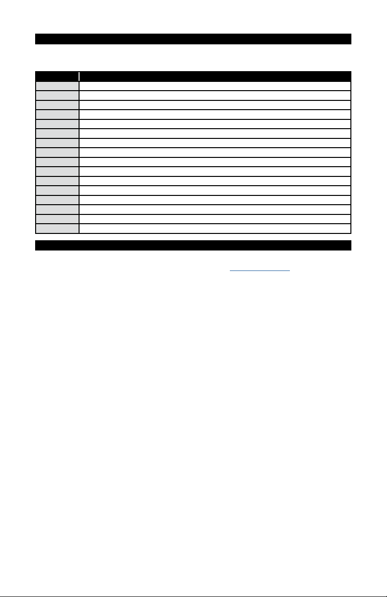
The following tools are required for assembly of this product:
2, 2.5, 3, 4, 5mm Allen keys
3, 4, 5mm socket Allen keys
ReachR, PullR, PointR tools
Torque wrench
Cable and housing cutters
High-quality grease
Blue threadlocker (Loctite 242)
The ReachR, PullR and PointR tools are custom tools designed to aid in the efficient and correct assembly of the
Venge ViAS Disc bicycle.
GENERAL NOTES ABOUT MAINTENANCE
The Specialized Venge ViAS Disc is a high performance bicycle. All regular maintenance, troubleshooting, repair
and parts replacement must be performed by an Authorized Specialized Retailer. For general information regarding
maintenance of your bicycle, please refer to the Owner’s Manual. In addition, routinely perform a mechanical safety
check before each ride, as described in the Owner’s Manual.
• Great care should be taken to not damage carbon fiber or composite material. Any damage may result in a loss of structural
integrity, which may result in a catastrophic failure. This damage may or may not be visible in inspection. Before each ride,
and after any crash, you should carefully inspect your bicycle for any fraying, gouging, scratches through the paint, chipping,
bending, or any other signs of damage. Do not ride if your bicycle shows any of these signs. After any crash, and before you
ride any further, take your bicycle to an Authorized Specialized Retailer for a complete inspection.
• While riding, listen for any creaks, as a creak can be a sign of a problem with one or more components. Periodically examine all
surfaces in bright sunlight to check for any small hairline cracks or fatigue at stress points, such as welds, seams, holes, and points
of contact with other parts. If you hear any creaks, see signs of excessive wear, discover any cracks, no matter how small, or any
damage to the bicycle, immediately stop riding the bicycle and have it inspected by your Authorized Specialized Retailer.
• Lifespan and the type and frequency of maintenance depends on many factors, such as frequency and type of use, rider
weight, riding conditions and/or impacts. Exposure to harsh elements, especially salty air (such as riding near the ocean
or in the winter), can result in galvanic corrosion of components such as the crank spindle and bolts, which can accelerate
wear and shorten the lifespan. Dirt can also accelerate wear of surfaces and bearings. The surfaces of the bicycle should
be cleaned before each ride. The bicycle should also be maintained regularly by an Authorized Specialized Retailer, which
means it should be cleaned, inspected for signs of corrosion and/or cracks and lubricated. If you notice any signs of
corrosion or cracking on the frame or any component, the affected item must be replaced.
• Regularly clean and lubricate the drivetrain according to the drivetrain manufacturer’s instructions.
• Do not use a high pressure water spray directly on the bearings. Even water from a garden hose can penetrate bearing seals
and crank interfaces, which can result in increased bearing and crank wear, which can affect the normal function of the
bearings. Use a clean, damp cloth and bicycle cleaning agents for cleaning.
• Do not expose the bicycle to prolonged direct sunlight or excessive heat, such as inside a car parked in the sun or near a
heat source such as a radiator.
WARNING! Failure to follow the instructions in this section may result in damage to the components
on your bicycle and will void your warranty, but, most importantly, may result in serious personal injury
or death. If your bicycle exhibits any signs of damage, do not use it and immediately bring it to your
Authorized Specialized Retailer for inspection.

4
SPARE PARTS
The spare parts listed below are either not referenced in other parts of the manual, or have been identified as
frequently needed.
PART # DESCRIPTION
S166800001 ELE MY16 VENGE VIAS SHIMANO DI2 BATTERY MOUNT FOR VENGE VIAS SEATPOST
S164700001 STC MY16 VENGE VIAS SEATPOST CLAMP KIT
S162500005 HDS MY16 VENGE VIAS HEADSET UPPER BEARING
S162500008 HDS MY16 VENGE VIAS HEADSET LOWER BEARING
S169900005 MSC MY16 VENGE VIAS GARMIN MOUNT
S159900006 MSC MY15 TARMAC MY16 VENGE VIAS DROPOUT EXIT FRAME PLUG FOR DI2 WIRE
S169900008 MSC MY16 VENGE VIAS REAR DER PLUG FOR MECHANICAL SHIFTING
S169900001 MSC MY16 VENGE VIAS BOTTOM BRACKET COVER
S169900002 MSC MY16 VENGE VIAS BOTTOM BRACKET COVER - DI2 HOLDER
S170200004 AXL MY17 ROAD THRU AXLE FRONT WITH 5MM BOLT ON 100MM X 12MM
S170200006 AXL MY17 ROAD THRU AXLE REAR WITH 5MM BOLT ON 142MM X 12MM
S170200005 AXL MY17 ROAD THRU AXLE FRONT WITH FIXED POSITION HANDLE 100MM X12MM
S170200007 AXL MY17 ROAD THRU AXLE REAR WITH FIXED POSITION HANDLE 142MM X 12MM
S160200001 SKW DT SWISS FRONT THRU AXLE WITH ROAD HANDLE 100MM X 12MM (RWS-10) (HWQXXX00S6708C)
S170200002 AXL MY17 DT SWISS RWS ROAD THRU AXLE REAR WITH ROAD HANDLE 142MM X 12MM
S152600003 HGR MY15-16 ROAD CARBON THRU AXLE DER HANGER
WARRANTY
A copy of the Specialized Limited Warranty Policy For Bicycles is provided with your bicycle, and is available from
your Authorized Specialized Retailer. It is also available for download at www.specialized.com.

5
STEM / STEERER TUBE PARTS
Many small parts for the stem and steerer tube are etched with one or more icons to denote if the part is for electronic
( ) or mechanical ( ) shifting (exceptions include the spacer stack parts and the steerer tube expander plug).
The Venge design offers a wide range of frame and component options to help the rider find the perfect position.
This range is provided through a combination of the following variables:
• Frame stack and reach - 7 size options: 46, 49, 52, 54, 56, 58, 61cm
• Spacer stack - 15 stack options: 6.5-75.5mm in 5mm increments
• Stem length - 7 options: 70, 85, 95, 105, 115, 125, 135mm
• Handlebar rise - 8 options: 0, 25mm rise x 38, 40, 42, 44cm width
• Seatpost length/setback - 6 options: 330, 380mm length x 0, 20, 35mm setback
STEM TOP CAP
S164800008
VENGE STEM
70mm: S164800013
85mm: S164800014
95mm: S164800015
105mm: S164800010
115mm: S164800011
125mm: S164800012
135mm: S164800016
STEM SHIM
MECHANICAL SHIFT : S164800001
ELECTRONIC SHIFT: S164800002
EXPANDER PLUG - DISC
S162500006
COMPRESSION RING - DISC
MECHANICAL SHIFT: S162500003
ELECTRONIC SHIFT: S162500001
CABLE GUIDE - MECHANICAL SHIFT
S164800003
VENGE SEATPOST
380 x 0mm: S164900001
380 x 20mm: S164900002
380 x 35mm: S164900003
330 x 0mm: S164900006
330 x 20mm: S164900007
330 x 35mm: S164900008

6
STEERER TUBE SPACER (LOW STACK)
HEIGHT: 5mm
S172500003 (x2)
STEERER TUBE TOP CAP (LOW STACK)
HEIGHT: 6.5mm
S172500010
TOP SPACER (HIGH STACK)
HEIGHT: 4mm
S172500002
STEERER TUBE SPACER (HIGH STACK)
HEIGHT: 5mm
S162500016 (x1)
STEERER TUBE SPACER (HIGH STACK)
HEIGHT: 10mm
S162500012 (x1)
STEERER TUBE SPACER (HIGH STACK)
HEIGHT: 20mm
S162500014 (x2)
STEERER TUBE TOP CAP (HIGH STACK)
HEIGHT: 16.5mm
S172500001
VENGE AEROFLY HANDLEBAR (0mm RISE)
38cm: S160800008
40cm: S160800001
42cm: S160800002
44cm: S160800003
VENGE AEROFLY HANDLEBAR (25mm RISE)
38cm: S160800007
40cm: S160800004
42cm: S160800005
44cm: S160800006
LOW STACK: Choose the LOW STACK TOP CAP (S172500010 - 6.5mm tall). Add either one or two 5mm low stack
spacers.
HIGH STACK: Choose the HIGH STACK TOP CAP (S172500001 - 16.5mm tall) and the HIGH STACK TOP SPACER
(S172500002 - 4mm tall). Add the desired combination of high stack spacers (5/10/20mm spacers, total 0 to
55mm) between the top cap and the top spacer.

7
1. FRAME FIT (ViAS SETUP)
A. DETERMINING FIT
Install the drivetrain on the frame (bottom bracket, crank, pedals, rear wheel, derailleurs and chain).
1
A
2
3
B
C
Fig.1: Install the lower headset bearing
A
(S162500008) on the fork.
Fig.2: Install the fork in the head tube.
Fig.3: Install the upper bearing
B
(S162500005).
Fig.3: Install the compression ring
C
(S162500001 or S162500003).
4
BRAKE GUIDE - BACK
ELECTRONIC:
S164800002
MECHANICAL:
S164800001
SHIM SLOT - FRONT
D D
Fig.4: Install the stem shim
D
(S164800001 or S164800002) into the stem. Make sure the etchings are on top
and the arrow is pointing toward the front of the bike.

8
5
F
F
E
G
H
I
J
K
LOW STACK OPTION:
6.5-16.5mm
HIGH STACK OPTION:
20.5-75.5mm
LOW STACK OPTION:
STACK HEIGHT 6.5mm LS TOP CAP (E) 5mm LS SPACER (F) 5mm LS SPACER (F)
6.5mm X
11.5mm X X
16.5mm X X X
HIGH STACK OPTION:
STACK
HEIGHT
16.5mm HS TOP
CAP (G)
5mm HS SPACER
(H)
10mm HS
SPACER (I)
20mm HS
SPACER (J)
20mm HS
SPACER (J)
4mm TOP
SPACER (K)
20.5mm X X
25.5mm X X X
30.5mm X X X
35.5mm X X X X
40.5mm X X X
45.5mm X X X X
50.5mm X X X X
55.5mm X X X X X
60.5mm X X X X
65.5mm X X X X X
70.5mm X X X X X
75.5mm X X X X X X
Specialized recommends using a stationary trainer and working with an experienced fit
professional. Since the fork must be cut to the correct height before the bike can be built and
ridden, determining the proper fit is more important than with a traditional bike.
To help transfer measurements from a current bike, use the Venge ViAS Sizing tool, located at https://www.retul.
com/venge-vias-sizing/.
Install the front wheel and place the bike in a stationary trainer.
Fig.5: If stack/reach are already known measurements, choose the spacers (low stack or high stack), stem and
handlebar that correspond to the desired stack/reach.

9
If stack/reach are not yet known measurements, start experimenting with different spacer stacks, stem lengths,
handlebar heights/widths and handlebar/brake lever positions.
Fig.5: Assemble the chosen spacer stack in order. The spacers are keyed to fit either the low or high stack
configuration. Low and high stack parts cannot be interchanged.
6
L
7
N
M
MARK POSITION
LOWER EDGE:
NO GAP
UPPER EDGE:
LARGE GAP
8
Fig.6: Install the stem
L
onto the steerer tube (the steerer tube will stick out the top of the stem, which is ok at this
time). Do not torque! Tighten the bolts enough so that the stem doesn’t move.
Fig.7: Apply carbon friction paste to the surfaces between the stem, faceplate and handlebar. Install the
handlebar
N
against the stem. Adjust the angle of the handlebar until it’s in the desired position.
Fig.8: While holding the handlebar in its desired position, rotate the faceplate downward so that there is no
gap between the faceplate and the stem body, at the underside of the stem. The gap should only be above the
handlebar. Torque the stem bolts to 100 in-lbf (11.3 Nm).
If the faceplate is not bottomed against the lower edge of the stem, the faceplate and handlebar can rotate
downward under rider weight until the faceplate bottoms out against the stem below the handlebar.
Fig.7: Install the brake levers
M
and adjust the angle until they’re in the desired positions.
Fig.7: Once the stack/reach and handlebar/brake lever angle positions are determined, mark the handlebar and
lever positions, then disassemble the handlebar from the stem.
B. ADJUSTING SADDLE AND SEATPOST POSITION
To prevent damage to the frame and/or seatpost, it is important to have a minimum amount of insertion in the seat tube.
Use the sight hole in conjunction with the minimum insertion/maximum extension (min/max) mark on the seatpost.
The seatpost MUST be visible through the sight hole, AND the seatpost must be inserted into the frame deep
enough so the min/max mark on the seatpost is not visible.
If the seatpost is at the min/max mark and the seatpost is not visible through the sight hole, the seatpost is not
inserted deeply enough into the seat tube and should be lowered until it can be seen through the sight hole. This
may result in the saddle being too low. If so, the seatpost must be replaced with a longer seatpost.

10
WARNING! Your seatpost and frame BOTH require a minimum amount of insertion into the frame
in order to maintain structural integrity. If your seatpost is not inserted deep enough into the seat
tube to meet BOTH requirements, it may result in damage to the frame and/or seatpost, which
could cause you to lose control and fall.
If the seatpost is cut short, the min/max mark on the seatpost may no longer be accurate. Before
cutting the seatpost, note the min/max depth required by the seatpost manufacturer.
WARNING! For general instructions regarding the installation of the seatpost, refer to the appropriate
section in the Owner’s Manual. Riding with an improperly tightened seatpost can allow the saddle to
turn or move and cause you to lose control and fall.
WARNING! Inspect the seatpost and seat tube to ensure that there are no burrs or sharp edges.
Remove any burrs or sharp edges using fine grit sandpaper.
CAUTION: The shape of the seat tube is not continuous. This limits the maximum insertion depth
of the seatpost When the seatpost is fully inserted, back it out 10mm, which is the maximum
insertion depth of the frame. Be careful when lowering it into the seat tube to prevent damage.
If your seatpost is at its maximum insertion depth and the saddle is too high, the post needs to be
replaced with a shorter one or cut to size.
Do not apply grease to the contact surfaces between the seatpost and the seat tube. Grease
reduces the friction, which is critical to proper seatpost grip. Specialized recommends the
application of carbon assembly compound (fiber paste), which can increase friction between
carbon surfaces. Please visit your Specialized Authorized Retailer for additional information.
1
2
Fig.1: Apply grease as illustrated to the surfaces between the upper and lower wedge, as well as the barrel. bolt
threads and bolt head.
Fig.2: Insert the wedge assembly into the seat tube.
Fig.2: Apply carbon friction paste to the seatpost, then insert into the seat tube. The use of carbon friction paste
is required.

11
7x9mm
7x7mm
3ANGLED SURFACES
A
F
B BC CD
E
Tab into groove Align arrows
Fig.3: Apply grease as illustrated to the conical surfaces
C
of the clamp mechanism, then install them in the
seatpost
D
.
Engage the saddle rails into the slots of the conical portions of the clamp mechanism.
Ensure that the wedges are parallel to each other. If the wedges are offset relative to each other,
they can force the saddle rails to twist, which can result in permanently bent rails and an uneven
saddle position.
Place the outer cap portions
B
of the clamp mechanism over the saddle rails.
The seatpost hardware is available for 7x7mm round alloy rails, or 7x9mm oval carbon fiber rails.
Install the nut
A
. To avoid damage to the clamp mechanism, the arrows must align
F
to ensure the tab is
placed in the groove of the outer cap.
Fig.3: Install the bolt
E
. Use blue threadlocker (Loctite 242) on the threads, place into the opposite side outer
cap and thread into the nut. Tighten lightly.
Remove all burrs and square edges from the seat tube and seatpost surfaces in contact each other. These edges and
burrs can dig into the material, compromising the strength of the carbon.
Install the seatpost into the seat tube.
Adjust the saddle to the desired angle and fore-aft position.
Fig.3: Torque the seatpost bolt to 120 in-lbf (13.5 Nm).
Adjust the seatpost to the desired height for proper leg extension.
Fig.2: Torque the seat collar to 55 in-lbf (6.2 Nm).

12
2. FORK ASSEMBLY
A. CUTTING STEERER TUBE
1
A
2
A
B
3
B
C
STEM
EXPANDER
PLUG
STEERER TUBE
STEM SHIM
3mm MAX
1mm
Fig.1: Mark the steerer tube at the top of the stem shim
A
.
Remove the stem and parts (set aside for future installation).
Fig.2 & 3: Remove the fork and cut the steerer so that when installed, the top of the expander plug is 0-3mm
C
below the top of the shim. The expander plug lip is 1mm thick
B
.
If the steerer tube extends above the shim, it can result in contact between the expander plug and
the stem cap, which can prevent proper headset adjustment.
WARNING! Inspect the fork and stem to ensure that there are no burrs or sharp edges. Remove any
burrs or sharp edges using fine grit sandpaper.
WARNING! Do not apply carbon friction paste to the interface between the stem and the steerer
tube. Carbon friction paste at this location can result in steerer tube failure which can cause you to
lose control and fall.

13
B. INSTALLING THE FRONT BRAKE HOUSING AND EXPANDER PLUG
1
2
POINTR TOOL
EXPANDER BOLT
UPPER WEDGE
SLEEVE
LOWER WEDGE
STEERER TUBE
3
ALIGN POINTR
TOOL TOWARD
FRONT OF BIKE
FRONT BRAKE HOUSING
Fig.1: Route the brake housing up through the housing port in the fork leg until it exits out the top of the steerer tube.
Fig.2: Disassemble the expander plug, then route the brake housing up through each part of the expander plug.
Fig.2: With the housing through the expander parts, reassemble the expander plug and insert the PointR tool
into the expander plug to align the upper and lower wedges.
Fig.3: Install the expander plug in the steerer tube, then orient the parts so that the PointR tool, expander arrow
and expander mark are aligned with the fork, toward the front of the bike (see fig.4).
Fig.3: Torque the expander plug to 45 in-lbf (5.1 Nm).
The PointR tool
E
is a long custom Allen key designed to help align the expander plug with the
fork and stem (kit includes ReachR tool).
POINTR TOOL:
S165300010

14
4SHIM ARROW
EXPANDER ARROW
EXPANDER MARK
FRONT BRAKE
REAR BRAKE
ELECTRONIC WIRE
C. REMOVING THE EXPANDER PLUG (if necessary)
PULLR TOOL:
S165300011
Loosen the expander bolt.
Lightly tap the bolt down to dislodge the lower wedge.
The PullR tool is a custom tool designed to thread
into and remove the expander plug.
Thread the PullR tool into the upper wedge until it bottoms out
in the expander plug, then turn the lever clockwise to pull the
upper wedge out of the expander body.
Once the upper wedge is removed, the expander sleeve can be removed as well.
If the system is fully installed and the steerer tube needs to be cut shorter, the housing will have to be
removed from the fork and the housing installation steps must be repeated with a new piece of housing.

15
3. FRAME ASSEMBLY
ELECTRONIC WIRING / HOUSING LENGTH CHART
LOCATION LENGTH LOCATION LENGTH
Front Derailleur 500mm Shifters (x2) 350mm
Rear Derailleur 700mm Down Tube 1200mm
Battery (Seatpost) 1000mm Rear Brake 1700mm
For wireless shifting systems, disregard all steps for installing wires.
A. INSTALLING BRAKE / SHIFTER HOUSINGS IN FRAME (electronic)
FACTORY ROUTING: Junction B inside handlebar, junction A under bottom bracket.
1
BROWN:
ELECTRIC WIRING (ED)
RED:
REAR BRAKE (RB)
Insert the rear brake housing into the chainstay entry port (see chart on page 15 for specific housing length).
Route the housing over the bottom bracket shell and up the down tube until it exits at the head tube.
2
A
BC
D
E

16
Fig.1 & 2: Route the wires through the chainstay
A
, seat tube (battery
B
and front derailleur
C
) and down tube
D
, over/in front of the bottom bracket, then connect the wires to the junction A box. Use the BB guide door
E
designed specifically to contain the junction A box.
ALTERNATE ROUTING: Junction A attached to Garmin bracket, Junction B inside down tube.
3
4
Insert the rear brake housing into the chainstay entry port (see chart on page 15 for specific housing length).
Route the housing over the bottom bracket shell and up the down tube until it exits at the head tube.
Fig.3 & 4: Route the wires through the chainstay, seat tube (battery and front derailleur) and down tube, over/in
front of the bottom bracket, then connect the wires to the junction B box. Place the junction B box into the down
tube, then install the standard BB door.
5
Install a section of foam tubing over the brake housing to ensure the housing doesn’t rattle in the down tube.
Fig.5: Apply grease as illustrated to the bearing surfaces, then re-install the upper headset bearing.
Fig.5: Insert the shift wire and brake housing into their respective slots in the compression ring.
Fig.5: Apply grease as illustrated to the compression ring, then seat the compression ring into the upper bearing
with the arrow pointing toward the front of the bike.

17
B. INSTALLING BRAKE / SHIFTER HOUSINGS IN FRAME (mechanical)
FRAME HOUSING - RECOMMENDED STARTING LENGTH
LOCATION LENGTH
REAR BRAKE (RED) 2000mm
REAR DERAILLEUR (GREEN) 1650mm
FRONT DERAILLEUR (BLUE) 900mm
1
RED:
REAR BRAKE (RB)
GREEN:
REAR DERAILLEUR (RD)
BLUE:
FRONT DERAILLEUR (FD)
The following housing lengths are for the initial installation, for all frame sizes. Once routed, the
housings must be trimmed according to the instructions.
While order of installation is not critical, it’s recommended to follow the order below.
One at a time, insert each housing (rear brake, front and rear shift) into their respective entry ports (see chart on
page 15 for specific housing lengths). Route the housings over the bottom bracket shell and up the down tube
until they exit at the head tube.
Make sure the housings aren’t winding around each other in the down tube. Shine some light into the down tube
from the bottom bracket cable guide hole to make sure they’re not crossing.
Make sure the ends of the shift housings are clean cut with no metal burrs, and that the inner sheaths have been
fully opened using a pick or other narrow object.
Install a section of foam tubing over each length of housing to ensure the housings don’t rattle in the down tube.
Table of contents
Popular Bicycle manuals by other brands

Fresh Breeze
Fresh Breeze XCitor Owner's manual & service booklet

Kettler
Kettler Familiano C-10 Translation of the original operating instructions

Denver
Denver E Quick Rider X7 Instructions for use and maintenance

HASE Bikes
HASE Bikes TRETS user manual

yeep.me
yeep.me eSIXTEEN manual

HITWAY
HITWAY BK7 Quick installation guide