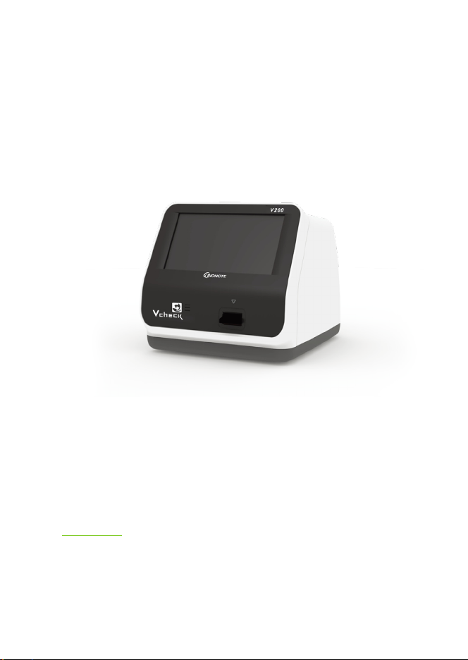
BioNote Vcheck V200 User manual

V200
Fluorescent Immunoassay systems
user manual
For veterInary use only

VC7402EA
Doc. No.: I7402-2E(CE)
Issued date : Sep. 05, 2017
Authorized Representative
Altenhofstrasse 80 D-66386 St. Ingbert Germany
Tel: +49-6894-581020 l Fax: +49-6894-581021
Manufactured by
Head oce
C-4th&5th, 16, Deogyeong-daero 1556beon-gil, Yeongtong-gu,
Suwon-si, Gyeonggi-do, 16690, Republic of Korea
Manufacturing site
74, Osongsaengmyeong 4-ro, Osong-eup, Heungdeok-gu,
Cheongju-si, Chungcheongbukdo, 28161, Republic of Korea
Tel: +82-31-300-0400 l Fax: +82-31-300-0499
www.sdbiosensor.com
Distributed by
22, Samsung 1-ro 4-gil, Hwaseong-si, Gyeonggi-do 18449,
Republic of Korea
Tel: +82-31-211-0516 l Fax: +82-31-8003-0618
www.bionote.co.kr
Thank you for your purchase of the BIONOTEV200
This user manual contains all the information needed to use the analyzer and keep it ready to operate. Please read this
user manual carefully before using the analyzer. Familiarize yourself with the required preparations and the measure-
ment procedure before performing the rst measurement. Please read the insert included in each test device package
before you try testing.
If you have any questions about the analyzer, please contact your healthcare professional or local distributor. You can also
visit www.bionote.co.kr for product demonstrations.
Thank you again for choosing the BIONOTE V200.

4
TABLE OF CONTENTS
CHAPTER 01. General Information
Main Menu Structure........................................................................................................................................ 6
Symbols and Abbreviation.............................................................................................................................. 10
Brief Precautions and Limitations................................................................................................................... 12
CHAPTER 02. Introduction
Intended Use ................................................................................................................................................... 13
Product Description......................................................................................................................................... 13
BeforeYou Start Testing .................................................................................................................................. 13
System Components ....................................................................................................................................... 15
CHAPTER 03. Settings and Performance
Operating the Analyzer................................................................................................................................... 19
Performing a Measurement ........................................................................................................................... 34
CHAPTER 04. Using the Analyzer Memory and Data Transfer
Displaying Stored MeasuredValues................................................................................................................ 41
Send Results .................................................................................................................................................... 42
CHAPTER 05. Quality Control
ControlTest ...................................................................................................................................................... 44
How to Perform Quality Control ..................................................................................................................... 45
CHAPTER 06. Calibration
Calibration SetTest.......................................................................................................................................... 48
How to Use the Calibration SetTest................................................................................................................ 49
CHAPTER 07. Cleaning and Maintenance
Cleaning the Analyzer..................................................................................................................................... 52
Maintenance andTransportation................................................................................................................... 52

5
CHAPTER 08. Screen Messages and Troubleshooting
Warning Messages.......................................................................................................................................... 53
Error Messages ................................................................................................................................................ 55
ANNEX 01. Information for Healthcare Professionals
Protection against Infections ......................................................................................................................... 58
ANNEX 02. Reference
Warranty ......................................................................................................................................................... 59
Return ............................................................................................................................................................. 59
Disposal ........................................................................................................................................................... 59

6
CHAPTER 01. General Information
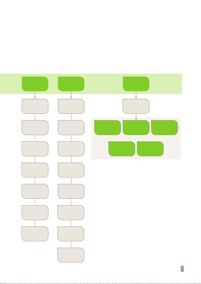
Main Menu Structure
Main
Standard Test Read Only Review
Login Login Q.C
Result
Search
Select
Calibration
Results
Detailed
Results
Send
Results
Patient
Results
Insert Device Insert Device
Device Check Device Check
Apply Sample Select All
Sample Check Delete
Analyze Delete All
Analyze
Finish
Finish
7
Q.C Calibration Supervisor
Login Login Password
Load/
Save
Setting
Update
Info
Manage
Operator
Insert Device Insert Device
Insert Device
Device Check Eject Device
Eject Device
Apply Sample
Analyze
Sample Check
Finish
Insert Device
Analyze
Finish

8
Send Results
Load / Save
Update Info
Manage Operator
Send Unsent Result
Settings Load Save
S/W Update View Version
Add
Send All Q.C Results
Save Test Records
Delete
Send All Patients Results
Send All Results
Operator ID Load Save
F/W Update View Network
Edit
Send Last Results
Send Selected Result
9
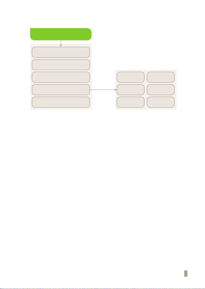
Settings
Set Print Option
Set Calibration and Q.C
Instrument Name
Set Timeout
General Settings
Date/Time Language
Units
LIS
Parameters
Network
Volume/
Brightness

10
Symbols and Abbreviation
Symbols
These symbols and abbreviations may appear on the packaging, on the labels, and in the instructions for the BIONOTE
V200.
Symbol Description
Manufacturer
Consult instructions for use
Reference number
Date of manufacture
To indicate the date of analyzer manufacture
Serial number
Note
Indicates that the product is fragile and to handle it with care
Batch code :
Indicate the lot number for the analyzer
Indicates to discard it separately from other household waste
This product fullls the requirements of European Low Voltage Directive 2014/35/EU (Low Voltage
Directive, LVD), Electromagnetic Compatibility Directive 2014/30/EU (EMC Directive), RoHS Directive
2011/65/EU
Indicate that you should keep the product dry
Caution!
Indicate a situation, which if not avoided could result in damage to the analyzer or incorrect results

11
Abbreviation
Abbreviation Description
cCRP Canine C-Reactive Protein
fSAA Feline Serum Amyloid A
Comm Communication
LIS Laboratory Information System
HIS Hospital Information System
GUI Graphic User Interface
S/W Software
F/W Firmware
BN BioNote, Inc.

12
Brief Precautions and Limitations
Caution
To reduce the risk of analyzer damage
· Keep the BIONOTE V200 analyzer on a at and dry surface and avoid direct sunlight
when operating
· The analyzer has internal correction for normal levels of ambient light, but highly
intense light entering the analyzer may cause serious interference with the results
and thus must be avoided
· Never move the analyzer while a test is in progress
· Do not drop the analyzer as the unit could be damaged
· Do not attempt to disassemble the analyzer
· Do not immerse the analyzer in water or cleaning solutions
To reduce the risk of incorrect results
· The analyzer should be used by trained operators
· Do not use if the analyzer is displaying an error message that cannot be corrected
· To obtain accurate results, refer to the test device package insert for test storage and
system operating conditions
· Using test devices that are expired can cause the results to be inaccurate
Potential
Biohazard!
To reduce the biohazard risk
· Dispose of used specimens in accordance with federal, state and local requirements
· Treat specimens as potentially biohazardous material
· Seek specic training or guidance if you are not experienced with specimen collection
and handling procedures
· Use of nitrile, latex, or other gloves is recommended when handling patient
specimens

13
CHAPTER 02. Introduction
Intended Use
The BIONOTE V200 analyzer is effective for measuring quantitative or qualitative biomarkers using body fluid in
the laboratory and point-of-care settings. The analyzer is indicated for monitoring and diagnoses using body uid
parameters in clinical settings by healthcare professionals.The analyzer should be used with the specied test device
produced by BioNote, Inc. Refer to the assay-specic package insert for details on specic tests.
Product Description
The BIONOTE V200 analyzer automatically recognizes the lot of the specic test devices in use by reading their 2D
barcodes. While the test device is inserted into the BIONOTE V200 analyzer, the application well of the test device is
illuminated by UV or RGB LED (light-emitting diode) with scanning. Before performing the measurement, the type
of the light reected determines the way the test device is analysed. When the specimen is applied, an enzymatic
reaction occurs forming a dye and the amount of formed dye is proportional to the concentration of the analyte.
The intensity of visual color or uorescence can be measured by illuminating with motor and LED, and detected by
reectance photometry. The measured value takes into account the signal strength of the light, measured a blank
value and information read including 2D barcode data. Finally, the test result is displayed on the screen and stored in
the memory of the analyzer simultaneously.
Before You Start Testing
Note
Read and follow the instructions carefully in the user’s manual and the Instructions for use of the
test device and control. It is very important to follow the instructions to prevent incorrect results
or improper treatment.
Specimens
The BIONOTEV200 analyzer should only be used with specic test devices for the analyzer. Because specimens are quite
dierent for each parameter, follow the instructions from each test device insert.
Safety information
There is a potential risk of infection. Healthcare professionals using the BIONOTE V200 analyzer to perform measurements
for more than one patient should use gloves and follow all other locally applicable health and safety regulations.

14
Operating conditions
To ensure proper function of the BIONOTEV200 analyzer, observe the following guidelines.
· Operate the analyzer only within the acceptable environmental conditions. Within the above range, the
acceptable temperature range varies depending on the reagent.
· To perform a measurement, place the analyzer on a at surface.
· Strong electromagnetic elds may impair the function of the analyzer. Do not use the analyzer close to sources
of strong electromagnetic radiation.
· The analyzer's air vents must be free for ventilation (Do not cover the air vents).
· If the analyzer experiences a sudden malfunction, unplug the adaptor from the outlet.
15
System Components
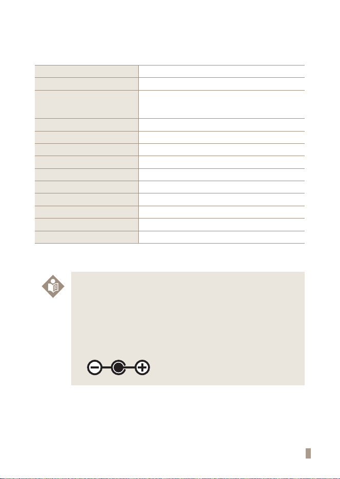
Unpack the shipping container and inspect the unit and components for damage.
Analyzer BIONOTEV200 Analyzer
Calibration Set BIONOTEVcheck Calibration Set
DC Power Supply
Input: AC100~240V, 50/60Hz
(Voltage tolerance ±10%)
Output: DC12V/5A
Display 7" ColorTFT LCD (800x480)
Display Controls Graphical User Interface
Power Consumption Max 50W
Over Voltage Category Ⅱ
Pollution Degree Ⅱ
Memory 3000
RTC RTC Backup Battery Included
Size 214.9 x 261 x 203 mm
Labeling User Manual
Barcode Scanner (Optional) Barcode Scanner
Note
· The AC/DC power adaptor is not supplied by BioNote, Inc. All users must use approved
Adaptor. (VDE, UL,TUV and etc.)
· Do not connect to the power supply other than AC/DC adaptor specified rating in the
specication.
· The size of Jack which connects with DC power adaptor is 5.5 mm, 2.5 mm (External, Internal
diameter).
· Must check adaptor polarity when plugging the adaptor into the device.

16
Overview of BIONOTE V200 analyzer
A
B
C
E
G
H
I
J
K
D
F

17
A. Color TFT LCD
Use for displaying the test screen and interacting with the graphical user interface
B. Test Slot
Slot for inserting a test device into the analyzer
C. Test Device
Use for initiating the test by inserting the specied test device
D. Printer Cover
Use for covering and protecting the printer sheet
E. Printer Cover Button
Use for opening the printer cover
F. DC Jack Port
Use for connecting the power supply adaptor 12V/5A to its compartment
G. Power switch
Use for turning on/o the analyzer
H. USB x 4
Use for connecting the keyboard, barcode scanner and USB drive
I. LAN
Use for communicating through the local area network
J. Mini USB
Use for upgrading the F/W upgrade by connecting to a PC
K. Additional Device Port
Use for connecting to specic devices manufactured by BioNote, Inc.
18
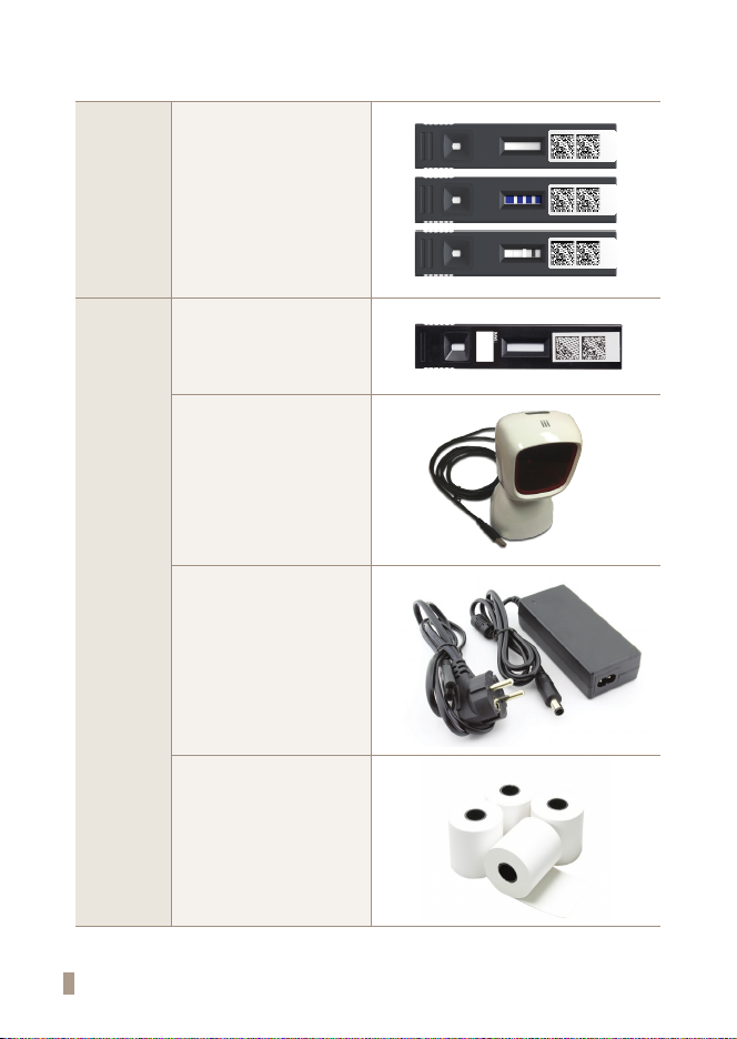
Accessories of the BIONOTE V200 analyzer
Included Calibration set
CAL-1 CAL-2 CAL-3
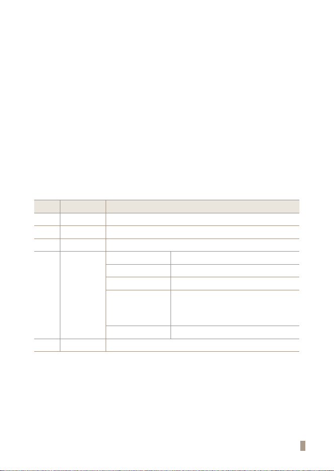
Optional
Test device
Barcode scanner
(For patient ID recognition)
12V/5A AC/DC
power adaptor
Print paper
19
CHAPTER 03. Setting and Performance
Operating the Analyzer
STEP 1. Connect AC/DC adaptor jack
1-1. Place the analyzer on a bench top within reach of an electrical outlet. The unit is portable and
can be moved to a suitable location for testing. Ensure the bench top is stable, at and dry. Also
ensure the bench provides adequate space for the analyzer and barcode scanner stand.
1-2. Plug the DC power cord into the power port in the back of the analyzer. Plug the country specic
AC/DC adapter power cord into an available electrical outlet.
1-3. Once the connection is complete, the analyzer is ready for use.
STEP 2. Setup the analyzer
2-1 When setting up the analyzer for the rst time, the operator's ID should be registered.The initial
supervisor password is 0000.
2-2 It is recommended to acknowledge the table presented on the supervisor menu.
Stage Menu Sub menu
1Manage Operator Add / Edit / Delete
2Load/Save Settings / Operator ID / Save test records
3Update F/W update, S/W update
4Settings
Print option Printed sheet 1/Printed sheet 2/Auto-printing
Time out Automatic turn-o time /Insert test device time
Calibration & Q.C Time period
General
Date/Time/Language/Units/Network/LIS/Volume/ /
brightness
※LIS/HIS can be set only when LIS/HIS server and
connection is ready.
Instrument name Instrument name/Facility name
5Info View version /View network

20
1st step: Entering setup mode
1. First, touch the 'Supervisor' button on the screen in the main menu to enter setup mode and begin the test.
2016. 10. 26 l16:18:57
2. Input the password and press‘OK’for entry. The initial password is 0000. Press‘Cancel’if you want to return to the
previous setting.
2016. 10. 26 l16:19:00
3. The supervisor menu the allows the operator to access additional functionality and security options depending
on the work environment and the location of the analyzer.
2016. 10. 26 l16:19:03
Table of contents
Other BioNote Medical Equipment manuals


