Bioprom AIR BIO User manual

1
OPERATION MANUAL FOR
AIR BIO
ELECTRONIC CONTROL UNIT FOR
SOLID FUEL BOILER
Kharkov city

2
WARNING!
ELECTRICAL EQUIPMENT CHARGED WITH ELECTRICITY!
Prior to carrying out of any actions associated with hooking up power supply wires,
please, make sure that AIR BIO control unit (hereinafter referred to as Controller) is not
connected to the electric power network! Assembling and connection to the electric power
network shall be done by the specialist with the corresponding authority for this type of
work. Before switching on the Controller it is required to verify grounding effectiveness of
electric motors, the boiler as well as inspect electric wires insulation.
Caution! You shall definitely earth AIR BIO Control unit. The Controller shall be
connected to the earth bar in accordance with «Operating and Maintenance Rules
for Electric Installations of Consumers».
1 INTRODUCTION
1.1 Product Purpose and Delivery Set
AIR BIO control unit is designed to ensure cost-effective and safe operation of a
solid fuel boiler for the central heating, hot water supply pump, a fan and fuel supply
system.
AIR BIO delivery set includes:
1. Network cable with plug tip 2 m long - 1 ea.;
2. Wire for hooking-up the fan with connector 0,5m long - 1 ea.;
3. Wire for hooking-up the pump 2m long - 2 ea.;
4. Wire for hooking-up the unit of automatic fuel supply 2m long - 1 ea.;
5. Temperature sensor with connecting wire 2 m long - 3 ea.;
6. Safety appliances - 2 ea.;
7. Operation Manual (passport) - 1 ea.;
8. Thermal protection sensor with connecting wire 2 m long - 1 ea.;
9. Clamp for fastening sensors, metal - 3 ea.
Additional options:
10. External alarm system - 1 ea.
1.2 Installation Requirements
Installation and adjustment of the Controller shall be carried out in the presence of
the qualified specialist. All installation works associated with installation/removal of the
unit or electric wiring shall be carried out only after power cut. Hookup diagram for the
control unit is shown on Picture 1, Picture 2, Picture 3.
AIR BIO Diagram
1. Network 220V6. Hot Water Supply Boiler Temperature Sensor
2. Central Heating Pump 7. Thermal Protection Sensor
3. Fuel Screw Feed 8. Central Heating Temperature Sensor
4. Hot Water Supply Boiler pump feed 9. Screw Feeder Temperature Sensor
5. Air Pressurization (fan feed)

3
Picture1 - AIR BIO Hookup Diagram
Picture 2 –AIR BIO Hookup to Central Heating System Diagram

4
Picture 3 –Diagram of hooking up sensors, external alarm system, and loads on Controller’s
board
1.3 AIR BIO Application Benefits
If using AIR BIO Control Unit for the solid fuel boiler the operator gets the following
advantages:
- fuel significant saving; because there is a capability to control burning intensiveness;
- capability to adjust Hot Water Supply temperature;
- capability to adjust Central Heating temperature;
- capability to adapt boiler operation to different types of fuel;
- safety: if Central Heating heat carrier starts boiling or temperature sensor breaks, the
safety system described in Item 3.3 is actuated.

5
2 DESCRIPTION
2. Description of the Controller components and control elements
Picture 4 –Controller External View
Power switch is intended for switching ON/OFF AIR BIO Control unit.
Safety fuse connector in intended to protect the unit from short circuit.
Control unit screen displays the boiler operation mode. When entering the «MENU» it
displays the menu items and modes for setting up the respective items.
Switch
ON/OFF
Switches ON/OFF the Controller. Instead of this button, there
might be on-off switch.
Central Heating Pump operation indicator
Hot Water Pump operation indicator
Fuel screw feed

6
Fan operation indicator. It is ON when fan is operating.
Emergency indicator. It is ON when working in an emergency
mode.
Menu button. When pressing this button, you enter the User
Menu and User Submenu.
Menu selection button, upward motion. You select menu
sections as well as increase the setup values.
Menu selection button, downward motion. You select menu
sections as well as decrease the setup values.
Exit button for getting back to the main page from the User
Menu. When pressing this button, you save the setup values of
the User Menu.
3 OPERATION
3.1 Controller Settings Description
If boiler temperature is lower than «Unit Switch Off Temperature»,it means that the
Controller is in «Standby»,mode in which all the loads are deactivated. If boiler temperature
is higher than «Unit Switch Off Temperature», it means that the Controller is in
«Operation», mode in which the blow-off (fan) operates on a continuous basis. Operation
time for fuel supply gear is set up by the consumer manually (the consumer set up both
operation time and interval time for fuel supply gear). If boiler temperature is equal or higher
than the preset temperature, the Controller is in «Standby»mode.
Each Controller shall be adjusted individually depending on the type of fuel used, and
boiler model.
The manufacturer is not responsible for consequences of improper setting up of the
Controller.
The Controller controls the fan with constant running capacity that is set up in the
User Menu with increments of 5% in the range of 0% to 100%. Once the preset boiler
temperature is achieved the Controller switches off the fan (moves to «Standby»mode). If
boiler temperature drops lower than the preset temperature up to the boiler hysteresis value
AIR BIO renews the fan operation (back to operation mode). When controlling the fan
operation in «Standby»mode, the Controller carries out periodic «Blow Off» of the boiler.
Operation duration and intervals for switching on the boiler blow off function are set
up in the User Menu.
Once the boiler reached «Pump Switch On Temperature», the Controller switches on
the central heating pump. If boiler temperature drops lower than «Pump Switch On
Temperature»minus «Pump Hysteresis», the Controller switches off the central heating
pump.

7
If boiler temperature drops lower than «Fan Switch Off Temperature», the Controller
switches off the fan. In this case it is considered that the boiler died down and further fan
operation is not reasonable.
When heat carrier temperature in the boiler drops lower than +5ºС, AIR BIO will
automatically switch on the central heating pump. This function is intended to prevent the
heat carrier from freezing in the heating system.
Boiler Hysteresis is the value that shows difference between the preset boiler
temperature and boiler temperature dropping to the value whereby the Controller again will
move back to «Operation»mode.
Pump Switch Off Hysteresis is the value that shows difference between the preset
«Pump Switch On Temperature»of central heating and boiler temperature dropping to the
value whereby the Controller will switch off the pump.
Pump hysteresis is set up by a user or an engineer independently.
3.2 Main Display
When supplying power and pressing «Power» button the Controller LCD display will
show the main page –User Menu with the following information:
STANDBY
t CH –XX/YY
t HWХ–XY/YX
ZZ% screw t –QQ
Picture 5 –Main Page
The first line describes the system status (Standby).
Below you will find readings of temperature sensors and their settings, where:
-XX –set value for boiler temperature, up to which the central heating heat carrier shall be
heated;
-YY –current value for central heating boiler temperature;
-XY –set value, up to which the hot water supply heat carrier shall be heated;
-YX –current value for hot water supply boiler temperature;
-ZZ% –fan power, %;
-QQ –current value of screw temperature.
The required value for the boiler temperature (YY) is set up on the main page of the
User Menu by pressing buttons ▲and▼. Boiler temperature can be set up within the range
of 45-95ºС.
«MENU» button is used for entering the User Menu.
3.3 Controller Menu
3.3.1 Manual Operation
For the sake of convenience the Controller is equipped with «Manual Operation»
function (when entering this menu section, all hooked-up to the Controller devices are de-

8
energized). This menu section is intended for the forced switching on and switching off
devices and units hooked up to the Controller.
Menu Functions:
а.) Screw: ON/OFF
This function allows switching on fuel supply in a forced manner for filling the screw
with fuel during its first start-up, clean-up, or check-up.
b.) Fan.
This function allows controlling fan operation with constant running capacity that is
set up in the User Menu with increments of 5% in the range of 0% to 100%.
c.) Central Heating Pump: ON/OFF
This function is intended for the forced switching on and switching off the pump,
check-up of its operability.
d.) Hot Water Supply Pump: ON/OFF
This function is intended for the forced switching on and switching off the pump,
check-up of its operability.
3.3.2 Firing: ON/OFF
This function is intended for starting up the cold boiler. When activating this function
you transfer the boiler from «Standby»mode to «Operation» mode («Standby»mode was
activated due to temperature drop lower than the limit set up in Item 7.7).
3.3.3 Fan
І. Pressurization Force: 0 –100%
This function controls fan operation efficiency. Adjustment limits are within the range
of 5% to 100% (conventionally it can be considered that these are steps of fan rpm).The
higher percent is the higher fan operation efficiency is.
ІІ. Blow off
Blow off function is intended for removing accumulated gases from the combustion
chamber when the boiler is in support mode.
«Blow off» includes two values: Pause –frequency of fan switch on and Operation –
duration of fan operation.
а.) Pause: value change limits from 1 to 250 (min.)
b.) Operation: value change limits from 1 to 250 (sec.)

9
Recommended pressurizer fan settings *
Fuel type
Heating output
kWatt*h/kg
Min power, %
Max power, %
Wood 20%
4,0
10
40
Wood 40%
3,3
10
60
Wood briquette
5,0
10
40
Peat briquette
5,4
10
60
Straw briquette
5,2
10
60
Anthracite
8,3
10
70
Brown coal
6,2
10
80
Small coal
6,4
10
100
CAUTION! Continuous, long-term operation of the fan might result in significant
rise of the preset boiler temperature and its «boiling up». Long duration of pause
time might result in flame failure in the boiler.
3.3.4 Screw Feed
This function is intended to adjust the operation cycle for the screw feed. The user sets
up operation time and breaks in screw feed operation.
І. Screw in «Operation»mode:
This function is intended for changing time lengths for fuel delivery to the furnace
when the boiler is in the mode of gaining temperature up to the preset value.
а.) Delivery time:
Value is set up from 1 to 250 sec. Delivery time is selected in accordance with boiler
capacity, fuel type, and fuel value.
b.) Pause time:
Value is set up from 1 to 250 sec. Pause time is selected in accordance with boiler
capacity.
ІІ. Screw in «Support»mode:
This function is required to maintain smoldering in the boiler during long-term staying
higher than the preset temperature (in support mode).
Caution! Quantity of supplied fuel in this mode shall be sufficient to maintain
smoldering. Too long load might result in boiler quench or its overheat!!!
а.) Delivery time: operation time for the screw in «SUPPORT»mode is set up 1 –250
sec. b.) Pause time: breaks between deliveries in «SUPPORT»mode are set up 1 –250
min.
ІІІ.) Screw switch off: ON/OFF
This function is intended for emergency switch off or switch on of fuel delivery as
well as when using AIR BIO without automatic fuel supply.

10
3.3.5 Boiler Operation Mode Selection
This function is intended for selecting one of three modes of boiler operation.
І. House Heating: ON/OFF
When activating this mode the heating system will give priority to heating the line of
the central heating pump.
ІІ. Parallel Pumps: ON/OFF
When activating this mode the heating system equally distributes the heat carrier to
heating lines depending on temperature ranges assigned by the user.
ІІІ. Summer Mode: ON/OFF
When activating this mode the heating system will be functioning only to maintain the
temperature of the hot water supply pump line.
3.3.6 Pumps
This function allows setting up the temperature value whereby the Controller will
switch on the central heating pump or hot water supply pump to supply heat carrier to this or
other system. Hysteresis value in this case is the value that shows difference between the
preset temperature of pump switch on and boiler temperature dropping to the value whereby
the Controller will switch off the Central Heating pump.
а.) Pump Switch on Temperature: changes within the range of 30–95°С
b.) Pump Hysteresis: changes within the range 1–10°С.
3.3.7 Adjuster Menu
This function allows adjusting basic parameters of the Controller’s program.
3.3.7.1 Screw feeder alarm switch on temperature: 50–95°С.
This parameter ensures safe operation of the boiler and protects fuel bunker from
burn-up. In case of temperature rise on screw sensor higher than the preset one in this item,
the Controller moves to the emergency mode (burn-up in the feeder). The fan switches off,
the screw feeder switches on for the time period set up in Item 7.2. to push out burning fuel
from the bunker.
3.3.7.2 Screw feeder operation during alarm: 1–20 min.
This parameter is intended for setting up screw feeder operation time for fuel off-
loading during its burn-up. If, in a certain time period the temperature on the sensor does not
drop up to the appropriate one, the off-loading cycle will be repeated.
3.3.7.3 Factory Settings: factory reset NO/YES
This function allows carrying out factory reset.
Once factory reset is done it is required to set up the Controller’s parameters again.
3.3.7.4 Sensors Switch off:
І. Hot Water Supply Sensor: on/off
This function allows deactivating control of hot water circuit in systems where it is not

11
used.
ІІ. Screw Sensor: on/off
This function allows switching off the screw temperature sensor in systems where
external fire fighting systems are used, to protect the screw feeder from reverse ignition.
3.3.7.5 Unit switch off temperature: 10 –75°С
If boiler temperature drops lower than the preset one AIR BIO Controller moves to
Standby mode. It is considered, that fuel in the bunker is over and further operation is not
reasonable.
3.3.8 Hot Water Supply Temperature:
Temperature change range: 40 –95°С.
The required temperature of hot water circuit is set up in this item.
3.3.9 Boiler Hysteresis:
Range: 1-10°С.
You set up the value up to which heat carrier operation temperature goes down from
the preset temperature whereby the Controller will transfer the boiler from «Support» mode
to the temperature gaining mode.
4 Controller Menu Structure
1.
Manual Operation
1.1.
Screw
OFF
1.2.
Fan
0%
1.3.
Central heating pump
OFF
1.4.
Hot water supply pump
OFF
2.
Firing
OFF
3.
Fan
3.1.
Pressurization force
30%
3.2.
Blow off
3.2.1.
Pause
5 min.
3.2.2.
Operation
30 se.
4.
Screw Feed
4.1.
Screw in Operation mode
4.1.1.
Supply time
10 sec.
4.1.2.
Break time
10 sec.
4.2.
Screw in Support mode
4.2.1.
Supply time
20 sec.
4.2.2.
Break time
5 min.
4.3.
Screw switch off
ON
5.
Boiler operation mode selection
5.1.
House heating
ON
5.2.
Parallel pumps
OFF
5.3.
Summer mode
OFF
12
6.
Pumps
6.1.
Pumps switch on temperature
45
6.2.
Pumps hysteresis
5°С
7.
Adjuster Menu
7.1.
Screw alarm switch on temperature
80
7.2.
Screw operation during alarm
1 min.
7.3.
Factory settings
Factory reset NO\YES
7.4.
Sensors switch off
7.4.1.
Hot water supply sensor
ON
7.4.2.
Screw sensor
ON
7.5.
Unit switch off temperature
25°С
8.
Hot water supply temperature
45°С
9.
Boiler hysteresis
5°С
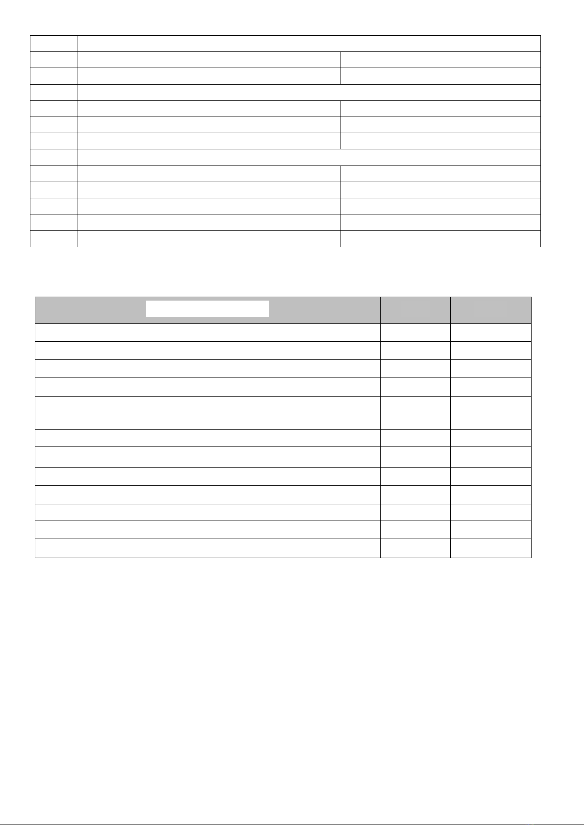
5 PERFORMANCE DATA
Parameter Description
UoM
Value
1. Power supply voltage
V/Нz
230 АС/50
2. Max power input
Watt
4.5
3. Automatic equipment operation temperature range
°С
+10 - +50
4. Circulating pump output load
Watt
500
5. Fan output load
Watt
1000
6. Screw feed output load
Watt
500
7. Boiler pump output load
Watt
300
8. Temperature measurement range
°С
0-95
9. Temperature measurement accuracy
°С
2
10. Temperature adjustment range
°С
45-95
11. Temperature sensor stability
°С
–55 - +125
12. Mass, not more
kg
3.15
13. Fusing element
А
10

13
6 APPLICATION INSTRUCTIONS FOR AIR BIO
6.1 Operating Restrictions
AIR BIO Controller for solid fuel boilers has the following operating restrictions:
Parameter Description
AIR BIO
Permissible humidity, %
from 40 to 90, non-
condensing
Permissible atmospheric pressure, kPa
from 84 to 107
Case proofness per GOST 14254
IP 41
Temperature sensor hardness, оС
from -55 to +125
6.2 Installation Rules
While installation and operation it is recommended to adhere to the following rules:
-the Controller shall be used for its intended purpose only.
-installation and removal of the Controller shall be carried out by the specialist
having the corresponding qualification;
-all installation works associated with installation/removal of the unit or electric
wiring shall be carried out only after power cut (disconnect plug 220V from the main);
-mistaken connection of electric wiring might result in damage of the Controller;
-central heating systems shall be equipped with safety valves, operating under
pressure, surge tanks, protective systems to ensure there will be no water boiling in the
central heating system.
-it is recommended to use the surge arrester for stable and accurate Controller
operation;
-it is prohibited to make any changes in electrical and mechanical knots of the unit.
Such changes might result in improper Controller operation or its breakdown;
-when hooking up the Controller make sure it will not cause overload in electric
network; avoid to hook up the unit to the same electric circuit along with engines and other
devices causing impulse interferences (e.g. washing machines, refrigerators, etc.);
-it is prohibited to allow the unit to undergo strikes or vibration;
-all connections shall be carried out in accordance with the electric installation
diagram and local norms on electric installations;
-it is prohibited to use the controller with damaged cables (wires); the damaged cable
shall be replaced by a special service company, the cable shall be new with the same
parameters as the original one.

14
6.3 Alarm Signs
AIR BIO Controller for solid fuel boilers provides for situations when emergency
messages might be sent:
-in case of «boiler overheat», when boiler temperature is more than +95ºС;
-in case of ignition in a screw feed, when temperature on the screw sensor is higher
than the temperature set up in Item 7.4.
-in case of temperature sensor failure;
Emergency Indicator lights up on the front panel, the Controller switches off the fan,
and at the same time the central heating pump continues uninterrupted operation cooling the
boiler by ducting the heat carrier through the central heating system. As well as AIR BIO
Controller provides for hooking up the external alarm system that will create closed-loop
(unclosed-loop) in case of emergency situation.
AIR BIO is additionally equipped with thermal protection sensor. The sensor is
intended for forced switching off the forced-draft blower and screw feed if the heat carrier
reaches abnormally high temperature in the heating circuit. 90 degrees in a standard way.
Response tolerance is 10%.
7 TECHNICAL MAINTENANCE
7.1 Safety
1. Installation and operation of AIR BIO Controller shall be performed in accordance
with fire safety regulations and electrical safety requirements.
2. Installation and adjustment of the Controller shall be carried out in the presence of
the qualified specialist.
3. It is recommended to install the Controller on the boiler in such a way to prevent it
from being dirtied and mechanically thermally damaged during boiler operation.
4. It is prohibited to use the Controller beyond the operating temperature range
specified in this Operation Manual.
5. It is prohibited to make any changes in the Controller construction at its own
discretion.
6. It is prohibited to locate the temperature sensor in fluids.
7. During operation it is necessary to ensure that there are no any contacts of wire
insulation with boiler heating up elements.
8. Safety appliance shall be replaced only when the Controller is off (disconnected
from power supply network) and with the safety appliance having the nominal specified in
this Operation Manual.
7.2 Technical Maintenance Procedure
When using the Controller, it is recommended to adhere to the following rules:
-it is recommended to hook up the unit using the surge arrester;
-it is recommended to clean up the boiler in accordance with the Boiler Manual
requirements;
-it is necessary to keep the unit away from moist environment and make sure that no
water will go inside the unit;
-it is recommended to wipe clean of dust, when required;

15
-installation, operation and repair of the Controller shall be carried out in strict
compliance with all the rules described in the Operation Manual;
-hookup, adjustment and technical maintenance of the Controller shall be carried out
by the qualified personnel that are familiar with the Controller configuration, hookup
diagram, НПАОП 40.1-1.21 and «Regulations for Operation of Consumer Electrical
Installations» (ПТЭ);
-it is required to check the technical condition of wiring prior to start of the heating
season and inspect it from time to time; it is also required to check stability of position of
the Controller during its operation;
-it is required to measure grounding effectiveness for the pump and fan.
7.3 Storage Instructions
The Controller shall be stored in closed heated premises in cardboard boxes under the
following conditions:
-surrounding air temperature from 0 to 40°С.
-relative air humidity of not more than 90% under temperature of 35°С.
-There should be no dust, fumes of acid and alkaline as well as aggressive gases in
the premises air.
8 WARRANTY OBLIGATIONS
1. The life cycle for AIR BIO Controller determined by LTD «Bioprom Company Kharkov»
is not less than 10 years.
2. LTD «Bioprom Company Kharkov» provides warranty for AIR BIO Controller for the
period of 18 months from the date of sale but not longer than 24 months from the date of
manufacture.
3. Warranty repair can be performed only by the company-manufacturer or it authorized
service centers.
4. Warranty repair is carried out within 3 working days from the date of receiving the
Controller by the service center, in certain cases the repair period can be prolonged up to 14
days.
5. Warranty is valid:
- only on the territory of the country where the Controller was purchased;
- 12 months on conditions that the Controller and the boiler have been operated
properly in strict compliance with manuals for the Controller and the boiler;
- if the user has not incorporated (made) any changes into the Controller configuration
and construction;
- if the works on putting the Controller into operation have been carried out by the
authorized representative of the manufacturing plant. The list of authorized representatives of
the manufacturing plant can be found on website of LTD «Bioprom Company Kharkov»
bioprom.ua.
6. Warranty does not cover damages occurred through:
- user’s fault due to improper installation of the unit and/or boiler;
- user’s fault due to violation of operation rules described in the present Manual or
Boiler Operation Manual;

16
- loss of the delivery set contents mentioned in Item 1. INTRODUCTION;
- willful damage;
- repair (or attempt to repair) performed by an unauthorized individual;
- power outages;
- use of low quality fuel;
- for the product that was installed and adjusted by a company or individual that are
non-authorized by the manufacturing plant;
- natural disasters (lightning strike, fire, flood, submergence, etc.).
7. In case of revealing defects mentioned in item 6, repair is carried out at buyer’s
expense, and a buyer will be notified thereof prior to start of repair.
8. When submitting the damage certificate it is required to add the description of a defect,
accurate return address and contact phone; otherwise the damage certificate will be reviewed
within the longer time period.
9 TRANSPORTATION
For the purpose of keeping (maintaining) the Controller integrity and proper
functionality during transportation one shall follow all the transportation conditions:
- temperature and humidity (see Item 3 of this Manual);
- stockpiling –not more than 10 ea.;
- rain protection;
- direct sun rays protection;
- crush protection;
- electromagnetic shielding.
8 UNIT DISPOSAL
It is prohibited to dispose the used unit in containers with domestic waste, the
Controller shall be sent to the special enterprise. Transfer of Controller decomposition
products to the environment might result in negative consequences.
9 REGULATORY HISTORY
All products of LTD «Bioprom Company Kharkov» undergo the certification process
(certificate validation) on a yearly basis as well as periodic test for interference immunity in
the State Enterprise «KharkovStandardMetrology». Certificates can be found on the
company sites.

17
10 INFORMATION ON PRICES AND PURCHASE CONDITIONS
All the data on prices and purchase conditions for the products of LTD «Bioprom
Company Kharkov» can be found on the company sites:
- www.bioprom.com.ua - www.bioprom.kh.ua
- www.bioprom.ua - www.bioprom.kharkov.ua
For all issues relating to warranty and post-warranty service, please feel free to contact
us at the address of: 126/1, Plekhanovskaya Str., Kharkov city, 61037.Telephone of Service
Center: +38(095)654-67-19, +38(098)232-52-15. E-mail –no12service@bioprom.com.ua.
You can watch video on LTD «Bioprom Company Kharkov» product operation on the
company sites.

18
For Notes

19
For Notes

20
Warranty Ticket
# ____________________
In accordance with the mentioned conditions the warranty for AIR BIO Controller is
granted for a period of 18 (eighteen) months from the date of sale but not longer than 24
months from the date of manufacture, and on conditions that the Controller is used in strict
compliance with the manufacturer’s specification.
Unit is checked by:______(Full Name)___________(signature)
Serial Number ______________________
Date
Manufacturer’s Signature and Stamp
_______________________
Date of Sale
Seller’s Signature and Stamp
______________________
LTD «Bioprom Company Kharkov»
126/1, Plekhanovskaya Str.
Kharkov Region
Kharkov, Ukraine
tel. +380 57 757-68-33
Email: info@bioprom.com.ua
www.bioprom.ua
www.bioprom.com.ua
www.bioprom.kh.ua
Table of contents
Popular Control Unit manuals by other brands

Lippert Components
Lippert Components OneControl X1 OEM INSTALLATION MANUAL

CALEFFI
CALEFFI ThermoSetter 1164 Series Installation, commissioning and servicing instructions

BD Sensors
BD Sensors AX16-DL 01 operating manual

Carel
Carel E2V S0 Series user manual

Whadda
Whadda Arduino 3.3 V user manual

SEA
SEA USER 1 - 24v DG R1 manual


HomeMatic
HomeMatic CCU2 HM-Cen-O-TW-2 Series Installation and operating manual

SMC Networks
SMC Networks XT323-4 user manual

Dennerle
Dennerle Profi-Line Instructions for use

AJH Synth
AJH Synth MiniMod Dual Contour user guide

Lightronics
Lightronics TL - 112 owner's manual

Murata
Murata 1PS installation manual