SEA USER 1 - 24v DG R1 User manual

USER 1 - 24V DG MAXI
SEA S.p.A.
Zona Ind.le S. Atto - 64020 S. Nicolò a Tordino (TE)
Tel. 0861.588341 - Fax 0861.588344
www.seateam.com
e-mail: [email protected]
Sistemi Elettronici
di Apertura Porte e Cancelli
International registered trademark n. 804888
®
67411261
23024074
REV. 01 - 07/2016
Italiano
English
Français
Español
APPAR. ELETTRONICA 24V PER CANCELLI SCORREVOLI E BARRIERA
24V ELECTRONIC CONTROL UNIT FOR SLIDING GATES AND BARRIERS
ARMOIRE ELECTRONIQUE 24V POUR PORTAILS COULISSANTS ET BARRIERES
DISPOSITIVO ELECTRÓNICO 24V PARA CANCELAS CORREDIZOS Y BARRERAS

DESCRIPTION OF THE COMPONENTS
CN1 = Input/Output connector
CN2 = Pre-wired limit switch connector
CN3 = Not Pre-wired limit switch connector
CN4 connector= Master/slave
CN5 = Courtesy light output connector
CN6 otors connector= M
CN7 = Batteries connector - Quick connection
CN8 = Power connector
Cn9 = Jolly 3 connector
CNA = RX Receiver connector
CNE = Encoder connector
CNP = Programming connector
CNS = RF FIX receiver connector
EXP = External module connector
OK = Programming button
DOWN = Programming button
UP = Programming button
RL1 = Motors control relay
Rl2 = Motors control relay
RL3 = Light/dry output contact relay
PR1 = Rectifier bridge
F1 = Fuse 20 AT
Jp1 = Relay 3 activation
JP2 = Light/dry contact selection
TECHNICAL SPECIFICATIONS
Control unit power supply: 24 V~
Absorption in stand by: 30 mA
Maximum motor current: 20A
Environment temperature: -20°C +50°C
Specifications of external enclosure: 305 x 225 x 125 mm - Ip55
English
USER 1 - 24V DG MAXI
156 mm
100 mm
RX RECEIVER
JOLLY3
CN8 F1
CNA
CN9
CN5
CNP
RL1
CN4
UP DOWN OK
PR1
DISPLAY
EXP
POWER FUSE MOTOR LIGHT
MASTER/SLAVE
PROG
RADIO MODULE
JOLLY
CNE
ENCODER
1
CN7
RL2
CNS
CNS CN2
CN3
LIMIT SWITCH
- S +
RL3
JP2
JP1
CN1
CN6
22
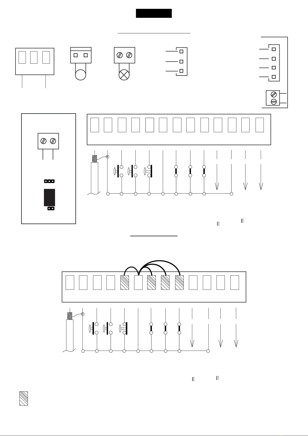
CONNECTIONS
JUMPERS
The herein reported functions
are available starting from
revision 01.21 compatible only
with Jolly 3.
English
123 4 5 6 7 8 910 11 12 13
CN1
Start
Stop
Common
Antenna
START Ped.
Common
Photocell 1
Common
ANT COM START
PEDST
STOP COM PH1 PH2
EDGE
AUX
COM 24V (FL)-
24V 750 mA max
(Accessori)
Safety edge
Flash (-)
Photocell 2
+ +
- -
123 4 5 6 7 8 910 11 12 13
CN1
ANT COM START
PEDST
STOP COM PH1 PH2
EDGE
AUX
COM 24V (FL)-
Start
Stop
Common
Antenna
START Ped.
Common
Photocell 1
Common
24V 750 mA max
(Accessori)
Safety edge
Flash (-)
Photocell 2
+ +
- -
Optional
WARNING: The control unit is designed with the automatic detection of not used N.C. inputs (photocells, Stop and Limit switch) except the
SAFETY EDGE input. The exclude inputs in self-programming can be restored in the “Check inputs” menu without need to repeat the
programming (pag.33).
Limit switch Cl.1 (Yellow)
Limit switch Cl.1 (Yellow)
24V (Red)
Common (White)
Limit switch Op.1 (Green)
Limit switch Op.1 (Green)
MOTOR (CN6)
Max 400W
ENCODER (CNE)
1
Brown
White
Green
USER 1 - 24V DG MAXI
AUX Programmable
(24V 300 mA max)
AUX Programmable
(24V 300 mA max)
1
LIMIT SWITCH
CN2
CN3
LIGHT (CN5)
Light/Dry contact
M
LIGHT (CN5)
Max 100mA
POWER (CN8)
24V~
RL3
JP2
JP1
23

QUICK SELF-EARNING
PROGRAMMING
Start quick programming
You can start the quick programming by
holding UP for 5 s in the “Input check
menu", until the motor starts.
English
“Input check
menu"
USER 1 - 24V DG MAXI
Fast self-learning START command by
radio control
You can store the START button of the
remote control while pressing DOWN for 5 s
in the “Input check menu".
Once the writing "Press button" appears,
press the button of the transmitter, which
you want to store for the START command.
By pressing OK, you can exit the menu,
otherwise it will be left automatically after 5
seconds.
DISPLAY
UP DOWN
5 s 5 s
---
--
---
UP DOWN
24

UPDOWN
ALL OTHER PARAMETERS HAVE DEFAULT SETTINGS WHICH ARE USEFUL FOR THE 90% OF THE APPLICATIONS
BUT CAN BE HOWEVER SET THROUGH THE SPECIAL MENU. FOR ENTERING INTO THE SPECIAL MENU MOVE
ON ONE OF THE MENU AND PRESS THE UP AND DOWN BUTTONS AT THE SAME TIME FOR 5 S.
English
PROGRAMMING
QUICK START
MENU
SEA
SET
MENU
SEA
SET
MENU
SEA
SET
MENU
SEA
SET
MENU
SEA
SET
MENU
SEA
SET
MENU
SEA
SET
MENU
SEA
SET
MENU
SEA
SET
MENU
SEA
SET
MENU
SEA
SET
OK
2
3
5
6
7
8
9
OK
OK OK
OK OK
OK OK
OK OK
OK OK
OK OK
UP
UP
UP
UP
UP
UP
UP
PRESS
BUTTON STORED
TRANSMITTERS
START
MOTOR
REVERSE
MOTOR
LOGIC
PAUSE TIME
START IN
PAUSE
PROGRAM-
MING
TEST START
10
Skip this step if you do not want to program a transmitter
Press the
button of the
TX to be
stored
OK to exit
Menu or press
the button of
the next TX to
be stored
OKOK Choose the type of
motor with
UP or DOWN
To confirm and return
to main menu
Choose "ON" with UP or
DOWN button only if in
programming the motor starts
in opening
With UP or DOWN
choose
the desired logic
To confirm and return
to main menu
With UP or DOWN
choose a delay for
automatic closing
To confirm and return
to main menu
Skip this step
if you wna tto work
in half-automatic
logic
With UP or DOWN
Choose ON
To confirm and return
to main menu
With UP or DOWN choose ON
to start times learning
At the end of the selflearning
the control unit returns automatically
to the main menu
With
UP or DOWN Choose
ON to start test
To confirm and return to
main menu
Skip this step if a TX has already been stored
1
MENU
SEA
SET
MENU
SEA
SET
OK
UP
LANGUAGE ITALIANO
UP
MENU
SEA
SET
(See
page 26)
(See
page 26)
If the motor has
magnetic limit switches,
select "Magnetic"
in the special menu:
104 - SELECT LIMIT SWITCH
RECEIVER
MISSING
If on the display
appears the item:
Check if a receiver has
been connceted
(see page 22)
The gate will execute a CLOSING-OPENING-CLOSING CYCLE
UP
MENU
SEA
SET
OK
END
15
MENU
SEA
SET
OK
SPECIAL
MENU
16
UP
Press OK to return to the
display of the inputs state.
Press OK to enter the special menu.
PROGRAMMING
BUTTONS
OK
DOWNUP
USER 1 - 24V DG MAXI
To confirm and return
to main menu
Return to the
9-PROGRAMMING menu,
put the gate halfway and
repeat the times programming.
25
MENU Default
SET
MENU FUNCTIONS TABLE USER1 24V DG MAXI
Description Set value
English
Stop
Start Start
Stop
Unloch Storing of a command for
unlocking an electric brake
Italian
English
French
Spanish
2 - TRANSMITTERS
External module
Pedestrian Start
Clear memory
Delete A TX
External module
Pedestrian Start
Delete single transmitter
Delete transmitter memory
Olandese
1 - LANGUAGE
Español
English
Français
Italiano
Dutch
Italiano
Start
Pedestrian
Start
8 - START IN PAUSE
6 - LOGIC
Automatic
Open-stop-close-stop-open
2 buttons
Safety
Dead man
Open-stop-close-open
Automatic
Step by step type 1
Step by step type 2
Two buttons
Safety
Dead man
7 - PAUSE TIME Setting from 1s to 4min.
OFF
(semi-automatic logics)
In pause start is not acceped
In pause start is accepted
(See page 27)
1 240
Off
Off
On
Off
Off
5 - REVERSE MOTOR Off
On
Synchronized right motor
Synchronized left motor Off
9 - PROGRAMMING
10 - TEST START
15 - END
Start command
Times learning start
(See page 27)
Off On
Off On
Off
Off
Press OK to return to the display of the firmware version and to the one of inputs state.
16 - SPECIAL MENU Press OK to enter the special menu.
Open-stop-
close-open
USER 1 - 24V DG MAXI
End “Transmitters” menu output
Joint Joint
3 - MOTOR
Saturn fast-
Saturn
super fast
Saturn Fast - Saturn Super Fast
Saturn Fast - Saturn Super Fast
Centralina idraulica
Hydraulic unit
Please note:
currently not available
Lepus box chain Lepus box chain
Saturn 1500 - Lepus 2000
Saturn 1500 - Lepus 2000
Slim Slim
26
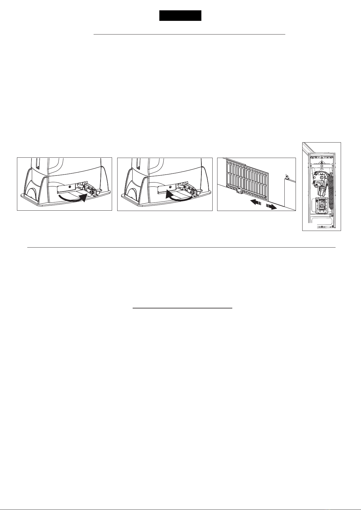
WORKING TIMES SELF LEARNING
English
Fig. 1 Fig. 2 Fig. 3
Fig.4
The control unit is pre-set with the default settings, to start the control unit with the DEFAULT settings just keep
pressed the UP and DOWN buttons at the same time power supplying the control unit the display shows the
message “Init”.
The DEFAULT settings are shown in the Menues table.
NOTE: When using a magnetic limit switches in general; make sure that the control unit is set on magnetic limit switch before
learning.
MENU 104 - SELECT LIMIT SWITCH - “Magnetic”
1) Disconnect the power supply, release the motor (Fig. 1) and manually position the leaves or the beam on halfway (Fig. 3-4).
2) Reset the mechanical lock (Fig. 2)
3) Select 9 - PROGRAMMING on the display, press OK and than one of the UP or DOWN buttons. Now the gate will automatically execute a
closing, opening and reclosing cylce.
Note: If the motor starts in opening, remove and re-put power supply, select on the display 5 - REVERSE MOTOR. And through the UP and
DOWN button put it on ON, or if you have the Jolly 3 programmer, activate the motor and limit switch exchange function. If the motor starts in
closing and stops, remove the power supply and reverse the motor cables, then repeat the programming procedure.
4)The self-learning is done.
ATTENTION: This procedure is potentially dangerous and should only be performed by qualified personnel in safety conditions.
FUNCTION LOGIC
AUTOMATIC LOGIC
A start impulse opens the gate. A second impluse during the opening will not be accepted.
A start impulse during closing reverses the movement.
SECURITY LOGIC
A start impulse opens the gate. A second impulse during opening reverses the movement.
A start impulse during closing reverses the movement.
STEP BY STEP TYPE 1 LOGIC
The start impulse follows the OPEN-STOP-CLOSE-STOP-OPEN logic.
STEP BY STEP TYPE 2 LOGIC
The start impulse follows the OPEN-STOP-CLOSE -OPEN logic.
NOTE1 : To have the automatic closing in this logic it is necessary to set a pause time , otherwise all the logics will be
semi-automatic
NOTE2: It is possible to choose whether to accept or not the start in pause, by selecting in the MENU point 8-START IN
PAUSE and choosing ON or OFF. The default parameter is OFF.
DEAD MAN LOGIC
The gate opens as long as the START button of opening is pressed; releasing it the gate stops. The gate closes as long as the
button connected to the PEDESTRIAN START is pressed; releasing it the gate stops. To execute complete opening and/or
closing cycles the related pushbuttons must be constantly pressed.
2 PUSH BUTTONS LOGIC
One start opens, one pedestrian start closes. In opening the closing will not be accepted. In closing a start command reopens, a
pedestrian start command (closes) will be ignored.
USER 1 - 24V DG MAXI
The SLIM motor has no limit switches and works only with Encoder. For the stroke learning it is necessary that the motor reaches the
mechanical stops. Learning provides a CLOSE-OPEN-CLOSE cycle with automatic detection of the mechanical stops. During normal cycle
the motor will stop at about 1 cm from the mechanical stop. This space will be regulated through the motor release parameter (meu 82).
Attention:
In case of the STOP command, power failure or obstacle detection, the motor will perform a closing maneuver at low speed up to the
mechanical stop in closing, to retrieve the position.
PROGRAMMING SLIM MOTOR WITHOUT LIMIT SWITCH
27

PRESS AT THE SAME TIME FOR 5 SECONDS TO ENTER OR TO EXIT THE SPECIAL MENU
MENU SP Default
SET
SPECIAL MENU FUNCTIONS TABLE USER 1 24V DG MAXI
For entering into the special menu move on one of the menu and press the UP and DOWN
buttons at the same time for 5 s. For exiting the special menu press END or move on one of the
menu and press the UP and DOWN buttons at the same time for 5 s.
Description Set Value
English
SPECIAL MENU
UPDOWN
30 100
17 - OPENING SPEED 1 *
18 - CLOSING SPEED 1 * 30 100
Setting from 30 to 100
Setting from 30 to 100
21 - OPENING SLOWDOWN
SPEED 1 *
22 - CLOSING SLOWDOWN
SPEED 1 *
30 100
30 100
Setting from 30 to 100
Setting from 30 to 100
25 - LEARNING SPEED * 30 100 Setting from 30 to 100
28 - OPENING TORQ 1 *
29 - CLOSING TORQ 1 *
10 100
10 100
On
xxx.
Encoder impulses during operation.
This parameter is useful for seeing if the
Encoder is working correctly.
Encoder impulses stored in programming
In ON enables the Encoder
32 - ENCODER *
xxx.
48 - ENCODER TOT. *
47 - ENCODER PAR. *
Off
32 - ENCODER *
In OFF disabled the Encoder
Off
33 - OPENING SENSITIVITY
MOTOR1 *
34 - CLOSING SENSITIVITY
MOTOR1 *
Disabled
Adjusts the intervention time
of the Encoder in opening
Off (Intervention excluded)
10% (Fast intervention)
99% (Slow intervention)
Disabled
Off (Intervention excluded)
10% (Fast intervention)
99% (Slow intervention) Adjusts the intervention time
of the Encoder in closing
35
35
* 70
* 70
* 40
* 40
* 75
* 70
* 70
ON
USER 1 - 24V DG MAXI
- - - - -
Shows the absorbed current
by the motor during the
movement. The letter H at the
left of the current value
indicates the exceeding of the
set inversion threshold.
57 - WORKING CURRENT
100% Maximum torque
10% Minimum torque
Enables the reading of
the potentiometer with
LE card.
Potentiometer
Reports the current position
of the potentiometer on the
leaf.
This parameter is useful for
seeing if the potentiometer
is read correctly.
Reports the impulses
stored by the control unit
when the leaf is fully open.
Reports the impulses stored
by the control unit when the
leaf is fully close.
32 - ENCODER * Off
- - - - - - - -
51 - I.PAR.M1 *
52 - I.AP.M1 *
53 - I.CH.M1 *
- - - - - - - -
- - - - - - - -
Note: Menus 47 and 48 are only present if the encoder is ON.
28

English
MENU SP Default
SET Description Set Value
0.0 5.0
Pre-flashing only
active before closing
85 - PREFLASHING Only closing
Pre-flashing time
0.0
1 100
82 - MOTOR RELEASE
Off Disabled
Setting from 1 to 100
Off
Buzzer Buzzer
86 - FLASHING LIGHT
Normal
Light
Always
Normal
Control lamp
Always ON Normal
Off
Off
On
The flashing light remains
ON with active timer and
open gate
The flashing light remains
OFF with the active timer
and open gate
87 - FLASHING LIGHT
AND TIMER
USER 1 - 24V DG MAXI
Off
Off
79 - ANTI INTRUSION Only closing
Only opening
Opening and closing
If you force the gate
manually, the control
unit starts the motor to
restore the state of the
gate before forcing.
0 100
Adjust the tolerance between
stop and obstacle opening
72 - OPENING TOLERANCE
MOTOR1 0
0 100
73 - CLOSING TOLERANCE
MOTOR1
Adjust the tolerance between
stop and obstacle closing
0
60 - CLOSING
SLOWDOWN 1 *
59 - OPENING
SLOWDOWN 1 * * 30
* 30
Off
5 100
Off
5 100
Disabled
Disabled
Setting from 5 to 100
Setting from 5 to 100
Acceleration ramp.
Adjusts the motor start.
0 15 6 %
0 15 6 %
70 - OPENING POSITION
RECOVERY
71 - CLOSING POSITION
RECOVERY
Retrieves the inertia of the
motor in opening after Stop
or reversing
Retrieves the inertia of the
motor in closing after Stop
or reversing
63 - DECELERATION
Adjust the passage
between normal speed
and slowdown speed
64 - ACCELERATION * * 70%
10%
Off
100%
0 %
100%
29

English
MENU SP Default
SET Description Set Value
USER 1 - 24V DG MAXI
Always AUX output always
power supplied
94 - 24V AUX
In cycle
In pause
Opening
Closing
AUX output power
supplied only during opening
AUX output power
supplied only during closing
AUX output power
supplied only during pause
AUX output active only
during cycle
Always
Fototest
In cycle and fototest
AUX output only during cycle
with fototest function active
AUX output for
connection of photocell
TX to autotest
Positive brake management
Positive Electrobrake
(output only when the
motor is stopped )
Negative brake management
Negative Electrobrake
(output only during cycle)
1 flash per sec. in opening
2 flashes per sec. in closing
Steady lit in Stop or Open.
Gate open warning
light
92 - TIMER
Off
On photo2 Off
On pedestrian entry
Transforms the selected
input in an input on
which to connect an
external clock.
Off on Off
89 - TRAFFIC LIGHT
RESERVATION
When setting this function
the pedestrian input will be
activated to work on the
auxiliary board SEM
(traffic light management).
20 100 30
90 - PEDESTRIAN OPENING
Setting from 20 to 100
= Start
91 - PEDESTRIAN PAUSE
Pause in pedestrian opening
same as in total opening
= Start
Off Disabled
1 240 Setting from 1s to 4 min.
In cycle
With J1 between 1 and 2,
and J2 not inserted, on CN5
you will have a dry contact
with activation of one "
second at each start impulse."
With J1 between 2 and 3,
and J2 not inserted, on CN5
you will have 24 volts always.
With J1 between 2 and 3, and
J2 inserted on CN5, you will
have 24V only during the cycle.
With J1 between 2 and 3, and
J2 inserted on CN5, you will
have 24 volts only during the
cycle plus for the set time.
Dry contact
1 240
Always
In cycle
88 - COURTESY LIGHT
30

English
MENU SP Default
SET Description Set Value
104 - SELECT LIMIT SWITCH *
Mechanical limit switch
Magnetic limit switch
Mechanical
Magnetic
Mechanical
USER 1 - 24V DG MAXI
Active in opening
and closing
Photocell active before
opening
Stop
Opening and closing
Closing Photocell active in closing
98 - PHOTO2
The photocell gives a
command to close during
opening, pause and
closing
The photocell stops in closing
and closes when released
Stop and close
Close Opening
And
clousure
The photocell charging the
pausing time
Pause reload
Delay pause time
If the photocell is occupied
during opening, pause or
closing, the gate reopens
completely and closes
without observing the
pause time.
99 - PHOTO OFF IN CLOSING 0 50 0
Setting from 0 to 50
100 - EDGE1 8K2
Edge is active and
protected by a 8k2 resistor
Normal N.C. contact
Normal
Normal
95 - FOTOTEST
Photo1
Photo2
Photo1-2
Auto-test active only on
Photo1
Auto-test active only on
Photo2
Auto-test active on
Photo1 and Photo2
Photo1-2
Stop
97 - PHOTO1
Opening and closing
Closing
Stop and close
Close
Pause reload
Active in opening
and closing
Photocell active in closing
Photocell active before
opening
The photocell gives a
command to close during
opening, pause and
closing
The photocell charging the
pausing time
The photocell stops in closing
and closes when released
Closing
Delay pause time
If the photocell is occupied
during opening, pause or
closing, the gate reopens
completely and closes
without observing the
pause time.
31
105 - MASTER-SLAVE
Master
Slave
Off
Off
For applications with two
motors in master-slave,
you can set the control
unit as slave
For applications with two
motors in master-slave, it
allows to set the control
unit as master
Disabled
1 10
Shows last event
106 - DIAGNOSTICS
0 10E9 0
100 10E4 10E3
107 - MAINTENANCE CYCLES
108 - PERFORMED CYCLES
Setting from 100 to
100000
Reports the executed
cycles. Keep pressed OK
to reset the cycles
112 - PASSWORD - - - -
Allows the entering of a
password blocking the
control unit parameters
modification.
- - - -
When ON, if no mains power
and batteries connected, the
gate will open fully and will
remain open until the power
returns. At this point it will
perform an automatic
reclosing.
113 - EMERGENCY Off On
Off
Press OK to exit the special menu.
The special menu switches off automatically after 20 minutes.
120 - BASIC MENU
Note 1: The * indicates that the default value or the parameter visualization may change depending on the
selected motor type.
Note 2: After initialization the parameters "motor type" and "limit switch type" remain son the value chosen in the
setup program.
English
MENU SP Default
SET Description Set Value
USER 1 - 24V DG MAXI
32

MENU
SEA
SET
DISPLAY INPUT STATUS
When the segment
is ON during self-
learning, the input
status is closed or
OFF.
Start
Start
pedestrian
Stop
Limit
Switch
opening
motor 1
Photocell 1
Photocell 2
Edge 1
Limit
Switch
closing
motor 1
Initial system
Software Version
Programming example
UP
OK
UP
UP
UP
DOWN
DOWN
DOWN
OK
OK
OK
DOWN
UP
0.0V
MENU
Exit menu
MENU FUNCTION TABLE CHECK USER1 24V DG MAXI INPUTS
To access the Menu for input check keep pressed OK for about 5 seconds.
Description Description
Start test The contact must be N.O. If activating the related command on the
display the item SET lights up, the input will be working.
If SET is always on, check the wirings.
Stop test
Pedestrian
start test
The contact must be N.C. If activating the related command on the
display the item SET lights up, the input will be working.
If SET is always on, make sure that the contact is a N.C. one
The contact must be N.O. If activating the related command on the
display the item SET lights up, the input will be working.
If SET is always on, check the wirings
Safety
edge test
Photocell 1
test
Photocell 2
test
The contact must be N.C. If activating the related command on the
display the item SET lights up, the input will be working.
If SET is always on, make sure that the contact is a N.C. one
The contact must be N.C. If activating the related command on the
display the item SET lights up, the input will be working.
If SET is always on, make sure that the contact is a N.C. One
The contact must be N.C. If activating the related command on the
display the item SET lights up, the input will be working.
If SET is always on, make sure that the contact is a N.C. one.
Opening limit
switch test
Closing limit
switch test
The contact must be N.C. If activating the related command on the display
the item SET lights up, the input will be working. If SET is always on,
make sure that the contact is a N.C. one or that the related
limit switch is not occupied.
The contact must be N.C. If activating the related command on the display
the item SET will light up, the input will be working. If SET is always on,
make sur that the contact is a N.C. one or that the related
limit swith is not occupied.
Batteries’
voltage level Batteries charge level indicator
OK
OK
OK
Note: If the Stop, Photocell 1 and Photocell 2 contacts are not bridged in self-learning, they will be deactivated
and can be reactivated through this menu, without repeating times self-learning.
OK
English
INPUT CHECK MENU
- - -
- -
- - -
VERG
SLIDING
JOINT
U.001
MOTOR
LIMIT SWITCH
CLOSING
LIMIT SWITCH
OPENING
START
EDGE
PHOTO1
PHOTO2
PEDESTRIAN START
END
STOP
Enabled
Blocked
Enabled
Blocked
Enabled
Blocked
Enabled
Blocked
The settings of the control unit are made through the UP, DOWN and OK buttons. The UP and DOWN buttons to scroll through the MENUS and
SUBMENUS. By pressing OK you enter from MENU into SUBMENU and confirm the choice.
Moving in the menu pressing the UP and DOWN buttons at the same time you access the SP MENU for special settings. 1-LANGUAGE
Moving in the menu pressing the OK button for 5 seconds, you enter the CHECK MENU, where you can check the operating 1-LANGUAGE
status of all inputs.
USER 1 - 24V DG MAXI
33

English
RADIO TRANSMITTER SELF LEARNING
WITH RECEIVER ON BOARD OF CONTROL UNIT
!
WARNING: Make the radio transmitters programming before you connect the antenna and insert the receiver into the
special CMR connector (if available) with turned off control unit.
With RF UNI and RF UNI PG module it will be possible to use both Coccinella Roll Plus transmitters and radio transmitters with fixed
code. The first memorized radio transmitter will determine the type of the remaining radio transmitters.
If the receiver is a Rolling Code, press twice the button of the radio transmitter that you want to program to memorize the first TX.
In the case of transmitters with fixed code it is necessary to press 1 time the button of the transmitter you want to program to store the first
remote control
Notes:
- Enter radio transmitters learning only when the working cycle stops and the gate is closed.
- You can store max. 2 of the available 4 functions. If the control unit receives a code which was already associated to another function it will be
updated with the new function.
MENU
SEA
SET
MENU
SEA
SET
MENU
SEA
SET
UP
MENU
SEA
SET
MENU
SEA
SET
MENU
SEA
SET
MENU
SEA
SET
UP
MENU
SEA
SET
MENU
SEA
SET
UP
MENU
SEA
SET
MENU
SEA
SET
MENU
SEA
SET
UP
MENU
SEA
SET
MENU
SEA
SET
UP
MENU
SEA
MENU
SEA
SET
MENU
SEA
SET
MENU
SEA
SET
SET
START
PEDESTRIAN
START
EXTERNAL
MODULE
STOP
DELETE A
TRANSMITTER
0OK? OK
CLEAR
MEMORY OK
PRESS
BUTTON STORED
STORED
STORED
STORED
PRESS
BUTTON
PRESS
BUTTON
PRESS
BUTTON
If you want to program
the pedestrian
start as second
channel.
If you want to
delete a single
transmitter.
If you want
to delete the
whole memory
If you want to program
the activation
of the LIGHT
output
as second channel.
Press the
button of the
transmitter
to be stored
Press the
button of the
transmitter
to be stored
Press the
button of the
transmitter
to be stored
Select with
UP or DOWN
the memory
location
to be deleted
and press OK
Press the
button of the
transmitter
to be stored
If you do not want to execute the cancellation,
press UP or DOWN to return to the
2-TRANSMITTER menu.
Confirm the cancellation.
If you want to
program the
UNLOCH as
second channel.
MENU
SEA
SET
MENU
SEA
SET
UP
MENU
SEA
SET
UNLOCH STORED
PRESS
BUTTON
Press the
button of the
transmitter
to be stored
If you want to
program the
STOP as
second channel.
OK
for 10 s.
MENU
SEA
SET
OK
TRANSMITTERS
OK
UP
OK
OK
OK
OK
OK
OK
MENU
SEA
SET
MENU
SEA
SET
If you want
to exit the
TRANSMITTERS
menu
Menu output
END OK
OK
USER 1 - 24V DG MAXI
1 2 3 4
0
1
2
3
TABLE EXAMPLE
Transmitter
button
Memory
location Serial number Customer
1 2 3 4
0
1
2
3
Transmitter
button
Memory
location Serial number Customer
16 USERS Whitout memory
800 USERS With additional memory MEMO
100 USERS Fixed code
800 USERS Roll Plus
800 UTENTI Fixed code
800 UTENTI Roll Plus
RF UNI
RF UNI PG
RF UNI PG
Old model without additional memory
New model with MEMO additional memory
34

CNS
CNS
RADIO TRANSMITTER SELF LEARNING
WITH RF FIX RECEIVER ON BOARD OF CONTROL UNIT
!
Connect the receiver on
the CNS connectors,
making sure that the
direction is the
one shown in the
illustration.
WARNING: Make the radio transmitters programming before you connect the antenna and insert the receiver
into the special CNS connector (if available) with turned off control unit.
With the RF FIX module it will be possible to use only radio controls with fixed code.
Select through the display 2-TRANSMITTERS and press OK, now select with the UP and DOWN buttons, the command to which
you want to associate the button (it is possible to associate max. 2 commands) and press OK to confirm the choice, now press the
button of the radio transmitter which you want to associate. If the storage is successful, the display will show “Stored” .
In the 2-TRANSMITTERS MENU it is possible to select “Start” (to associate a Start command), “Pedestrian start” (to associate a
Pedestrian Start ), “External Module” (For the activation of a contact on the EXP output), “Stop” (To associate the STOP
command to the TX), “Unloch” (to associate the release of the electric brake to the transmitter), “Delete a transmitters” (To delet
the single transmitter only if it is a Rolling Code Plus), “Clear memory” (To delete all TX), “End” (To exit menu 2-TRANSMITTERS).
To release the electric brake it is necessary to give three consecutive pulses, the 4th will reactivate the lock of the electric brake.
Notes:
- Enter radio transmitters learning only when the working cycle stops and the gate is closed.
- It will be possible to memorize up to max. 16 codes (buttons) adding the MEM memory it will be possible to store up to 496
different codes.
- You can store max. 2 of the available 4 functions. If the control unit receives a code which was already associated to another
function it will be updated with the new function.
DELETE TRANSMITTERS FROM THE RECEIVER
With modules different from RF FIX, it will be possible to delete only the entire memory of the receiver.
Proceed as follows: select from the menu 2-TRANSMITTERS: “Clear memory” and hold the OK button until the display shows the
message “OK”.
English
USER 1 - 24V DG MAXI
35

START (N.O.) The START is connected between the clamps 2 and 3 of the CN 1 terminal.
An impulse given to this contact opens and closes the automation depending onthe selected logic it can be given by a key switch, a keypad,
etc. To connect the other devices refer to the related instructions leaflets. (ie. loop detectors and proximity switches).
Note1: In DEAD MAN logic it is necessary to keep pressed the Start for the opening of the automation.
Note2: In 2 BUTTONS logic this button performs the opening.
STOP (N.C.) The STOP is connected between the clamps 2 and 5 of the CN1 terminal .
The pressure on this button immediately stops the motor in any condition/position. A start command is needed to re-start the movement.
After a stop the motor always re-starts in closing.
Photocell 1 and Photocell 2 Connections
+ = 24V (Accessories) max 750mA COM = 0V PH1 = Photocell contact 1
PH2 = Photocell contact 2
Note: For the autotest connect the TX to the AUX clamp and activate the Autotest function.
The standard setting of the photocell 1 is in “Closing” and the one of the photocell 2 is in “Opening
and losing” . The photocell 2 can be set also as TIMER (see TIMER function).
Note3: On the 95-FOTOTEST menu you can also activate the self-test even on the single photocell.
START - STOP - PEDESTRIAN START - ANTENNA -
PHOTOCELL
Can be activated through on-board display or through the Jolly 3 programmer. In both cases it’s a N.O. contact which
provoques the opening of the automation keeping it open until it is activated. When it’s released, the gate attends the set
pausing time and executes the reclosing. The TIMER command can be activated on the inputs FOTO2, START PEDESTRIAN.
Note1: When activated on the pedestrian entry, the pedestrian will be disabled also on the radio transmitter.
Note2: In case of intervention of a security device during the timer (Stop, Ammeter, Edge), to restore the movement it will be
necessary to give a start impulse.
Note3: In case of no power supply with open gate and active Timer the control unit will restore its use, otherwise if during
restore of the power supply the TIMER is not activated it will be necessary to give a start impulse for the reclosing.
TIMER
Common
Common
Photocell 1
Photocell 2
Common
24V (Accessories)
PEDESTRIAN START (N.O.) The pedestrian start can be connected
between the clamps 2 and 4 of the CN1 terminal .
This input allows a partial opening the opening space can be set through
the on-board display or through the JOLLY device.
Note1: The contact for partial opening is a N.O. Contact (Normally open).
Note2:In 2 BUTTONS logic it is necessary to press the Start Ped. to re-
close the automation.
Note3: In dead man logic this button executes the re-closing if you keep it
pressed.
Note4: When closed during pause, the gate will reclose only after this
input has been reopened.
TIMER activation: This input can be transformed into TIMER (See
TIMER).
Options AUX 24V max 300mA can be set with on-board
Display or with Jolly 3 device.
Through the Jolly 3 programmer it is possible to chose when having
tension on the AUX output. The options are: Always, In cycle,
Opening, Closing, In pause, Fototest, In cycle and fototest,
Positive brake management, Negative brake management, Gate
open warning light. When using control units with batteries and /
or solar panels, we recommend connecting the accessories which
are not used when operator stands still (e.g. photocells) to a AUX
output, setting the option “In cycle”. With this setting you can save
energy by lowering power consumption in stand-by, increasing the
autonomy of the system.
English
OPTIONS ON FOTO1 and FOTO2 adjustable on on- board display or with JOLLY 3
terminal.
“Closing”: if occupied, reverses the movement in closing, during pause it prevent the
closing.
“Opening and closing”: If activated the photocell blocks the movement as long as it’s busy,
when released the opening continues.
“Stop”: When activated before the opening the photocell blocks the automation as long as it
is busy, during the opening it will be ignored. In closing the intervention of the photocell
causes the reopening.
“Stop and close”: in opening it is not active; in pause are activated it commands the closing
when released, otherwise it’s not active; in closing it stops the movement as long as it is busy,
when released the closing continues.
“Close”: The photocell stops the gate as long as it is occupied in both opening and closing,
when released it gives a closing command (Closing one second after release of the
photocell).
“Pause reload”: If occupied, during pause it recharges the timer of pause. In closing it
reverses the movement.
“Delay pause time”: If the photocell is occupied during opening, pause or closing, the gate
reopens completely and closes without observing the pause time.
USER 1 - 24V DG MAXI
9 10 11 12 13
1 2 3 4 5 6 7 8
Antenna
Start
Start ped.
Stop
CN1
RX1
RX2
TX1
TX2
CN1
36

LIMIT SWITCH AND SENSOR BARRIERS
Sensor barriers
This control unit comes with a detection device of motor current absorbtion which allows to
reveal possible obstacles during the opening and the closing of the gate. When this device
intervenes in opening it causes the inversion of the movement for around a second, if it
intervenes in closing it causes the total reopening.
Note1: The sensitivity is adjustable both in opening and in closing through the on-board
display or through the JOLLY 3 terminal. With high torque the gate reverses after 5
seconds.
Attention: In case of obstacle, if the automatic reclosing is on, the gate will attempt to
close for 3 times, whereupon a start signal will be necessary to re-establish the
movment.
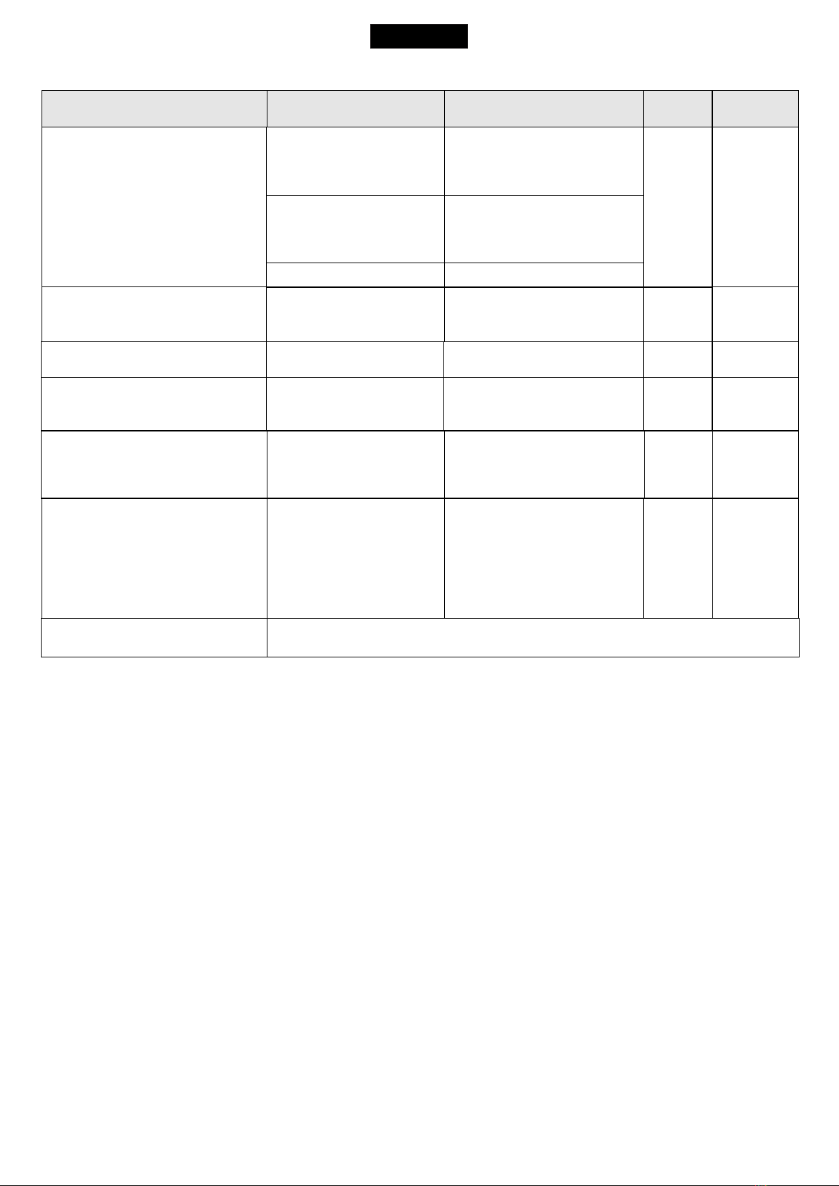
ALARMS INDICATIONS
Flashings Number
9
2
3
6
4
Flashings Number
5
7
6
4 fast
Kind of alarm
Motors fault
Photocell in closing
Photocell in opening
Opening impact
Safety edge
Kind of alarm
Stop
Max. Reached cycles
Closing impact
Limit switch error
Signals Kind of alarm Solutions
Motors current failure Sure there are no short circuits on the motor or on the control unit.
24V Power supply
failure
Make sure there are no short circuits on the wiring or on the control unit and
no overloads.
AUX output
voltage failure Make sure there are no short circuits on wiring or control unit and no overload.
Self-test photocells
failure Check the photocells operation and / or connections on the control unit.
Limit switch
activation failure Check the operation of both limit switches and / or correspondence
between movement direction of the motor and engaged limit switches.
Flashing lamp failure Check connections and / or conditions of the lamp.
Slave failure Check the connection between MASTER and SLAVE or if the SLAVE board is
actually set as such.
Limit switch
The limit switch can be connected through the special LIMIT SWITCH connector on
the control unit. The control unit can administrate mechanical, inductive and magnetic
limit switches. Only on some special applications il will not be necessary to connect
the limit switches. The control unit will automatically realize if limit switches are
present or not.
1) Through the on-board display or through the JOLLY 3 programmer it is possible to
activate the ani-intrusion function. This function is lied to the presence of at least one
limit switch which, when free, forces the motor to re-close.
Note: if during programming phase the motor and limit switch times should not
be in phase between them, the gate will start in closing, it stops and will not
complete the selflearning of the times, at this point it will be necessary to
switch off the tension and to invert the cables of the motor. The first movement
in selflearning must always be executed in closing.
ATTENTION: When using SEA magnetic limit switches, make sure that the
motor is set on “Magnetic” present in the special menu 104-SELECT LIMIT
SWITCH.
Note 1: If in the diagnostics shows "max. cycles reached ", do the maintenance and / or reset the number of cycles performed.
Note2: To exit from the error messages, press OK. If the error persists, make all required checks for the specific error and / or disconnect the
device that generates the error to see if the error disappears.
At each opening and closing of the automation the flashing light will blink. It blinks once per second during opening and twice per second
during closing, while it remains lit during pause.
It is possible to view the alarms also on the flashing light or on the control lamp, simply by observing the number of flashes emitted and
verifying the reference in the table below:
English
FAILURE MOTOR
FAILURE24
FAILURE24VAUX
FAILURE SELF TEST
FAILURE LIMIT SWITCH
FAILURE FLASHING LIGHT
FAILURE SLAVE
USER 1 - 24V DG MAXI
Failure Overcurrent-
Collision
FAILURE
OVERCURRENT-
COLLISION
Failure
Blocked motor
FAILURE
BLOCKED MOTOR
Check for obstacles or points of friction on the gate.
NOTE: the fault is reset by pressing OK.
Check the connection of the Encoder or if the motor is stopped mechanically.
NOTE: the fault is reset by pressing OK.
Note:
limit switch connection in
case of absence of the
plug-in connector.
Limit
Switch
CN2
CN3
COM
CN1
9 10 11 12 13
37
Edge
Common
Safety edge
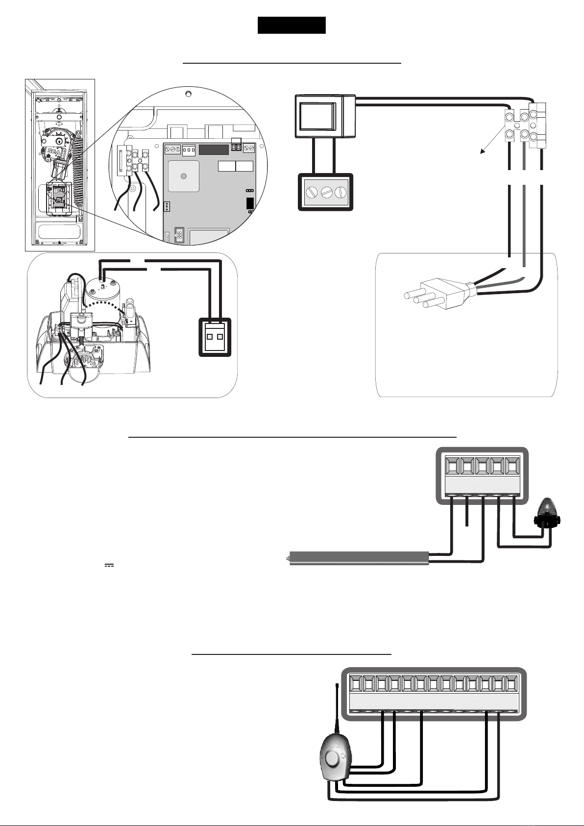
MOTOR POWER SUPPLY
Power input
Input for the connection of the electric
power.
P = PHASE
N = NEUTRAL
G = GROUND
N O T I C E: f o r t h e
connection to the
electric power see the
law in force.
TRANSFORMER
3,6 A blow fuse on 230V ~ power supply
6,3A blow fuse on 115V ~ power supply GN
115V~
o
230V~
P
P G N
MOTOR
(CN6)
M+ M- 12
SAFETY EDGE
Between clamps 9 and 11 of CN 1 it is possible to connect an active safety edge. If this device is pressed it
opens the contact causing a partial inversion of the movement both in opening and in closing. If not used
you must put a jumper between the contacts GND and 9 of CN1.
Note1: contact N.C.
Note2: Through the on-board display or the Jolly 3 programmer it is possible to activate the balanced
edge 8K2, in this case the edge contact is controled by a special resistance value revealing the eventual
involuntary short- circuit of the device. In case of imbalance of the device a special alarm will show on the
on-board dispaly or on the JOLLY 3 programmer.
Flashing Lamp 24V 15W (Warning lamp )
The flashing lamp can be connected between the clamps 24V ( ) and FL (-) of CN 1.Accessories
The warning lamp advises that the automatic gate is moving with 1 flash/second in opening and 2 flashes / second in closing. During pause it
remains switched on. Through the warning lamp it is also possible to identify alarms lied to the STOP, PHOTOCELL 1, PHOTOCELL 2 and
EDGE devices. Through the display or the JOLLY 3 programmer it is possible to activate the pre-flashing function and/or to modify the function
of the warning lamp choosing between fix flashing, control lamp or Buzzer.
SAFETY EDGE AND WARNING LAMP
EXTERNAL RECEIVER
Example: Connection of a
radio receiver
For the connection of the
receiver refer to the relative
instructions manual.
Common
Common
24V (Accessories)
24V (Accessories)
English
USER 1 - 24V DG MAXI
POWER
(CN8)
P G N
1 2 3 4 5 6 7 8 9 10 11 12 13
9 10 11 12 13
+
-
CN1
Start
Start ped.
AUX
FL(-)
CN1
38
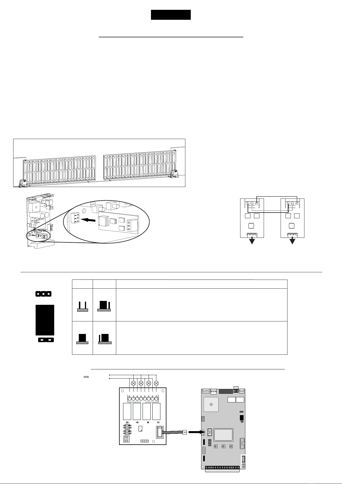
MASTER-SLAVE FUNCTION
To set an installation with two motors in MASTER-SLAVE function it is recommended to do as follows:
1) Set the two motors as if they were two independent installations, make sure that the individual motor works properly and that
the limit switches (when present) are read properly.
2) Once sure of the correct functioning connect the control unit MASTER to the control unit SLAVE through the special clamp
(Code SEA 23001220).
3) Now set the control unit, which has to manage the commands and motor 1 (photocell, keyswitch, STOP, safety edge etc.) as
MASTER and the other one which will move motor 2 as SLAVE.
4) Follow up the selflearning of the times of the MASTER control unit.
Note 1: The master and slave settings on the control unit are present in the special menu selecting 105-MASTER-SLAVE.
Note 2: All these operations can also be managed through the JOLLY 3 programmer).
Note 3: On the SLAVE it is possible to set the following functions only: torque, speed, motor type, slowdown speed, acceleration,
deceleration, position recovery, AUX and motor inversion.
All other parameters will be set only by the MASTER control unit.
TRAFFIC LIGHT CARD CONNECTION
Connect on
EXP terminal
English
USER 1 - 24V DG MAXI
Insert on CN4
of the Master control unit
Insert on CN4
of the Slave control unit
Note: respect the polarity of the cables.
It is recommended to
use a two twisted
pairs shielded cable
with less than 0.5
2
mm section.
MASTER SLAVE
CN4
This configuration is usable in the case of two
opposite sliding gates.
In this configuration, all devices (photocells, key
switch, edges, etc.) must be connected on the
MASTER unit which will also control the movement of
the motor linked to the SLAVE unit.
COURTESY LIGHT OUTPUT 24 VOLT / DRY CONTACT MANAGEMENT
8 - COURTESY LIGHT menu settings
SIGB
COM
SIGA
SIGB
COM
SIGA
M1 M1
RL3
JP2
JP1
With JP1 inserted and JP2 inserted between 2 and 3 of
CN5 you will have tension according to the setting given
by the menu 88 (one second from each pulse start, only
during cycle, always or for the set time).
JP1 JP2
1 2 3
1 2
1 2 3
With JP1 off and JP2 inserted between 1 and 2 of CN5 you
will have a clean contact that is activated based on the
setting given by the menu 88 (one second from each start
pulse, only during cycle or for the set time).
1 2 3
1 2
1 2
DS1
DS2
RL4 RL3 RL2 RL1
L4 L3 L2
IC2
- M2+
1 CNP
CN1
L1
M1
24V~ / (ac/dc)
o
230V~
1 2 3 4 5 6 7 8
1
2
3
4
39
English
PASSWORD ENTERING MANAGEMENT
With a new control unit all menus can be displayed and set and the password will be disabled.
Selecting one of the Menus and keeping UP and DOWN pressed at the same time for 5 seconds, you will access the SP Menu containing the
112-PASSWORD Submenu.
Pressing OK in the 112-PASSWORD Menu, you will proceed with the entering of the numeric code of the 4-digit password.
Use UP and DOWN to increase or decrease the number, press OK to confirm it and you will pass automatically to the entering of the next
number. Pressing OK after the last entered number the word “Sure?” appears, confirm the activation of the password and the message OK
appears, pressing UP or DOWN instead you can cancel the operation and “No operation” will appear on the display.
Once entered the password, it will be definitively activated, once the display switch off timeout has expired, or by turning off and on again the
control unit. Once the password has been activated, the menus of the display can be only displayed but not set. To unlock them you must enter
the correct password in the112-PASSWORD menu, if the password is wrong the message “Error” will appear.
At this point, if the password has been entered correctly, the menus will be unlocked and it will be possible to change the parameters of the
control unit again.
If the control unit has been unlocked through 112-PASSWORD Menu, it is possible to enter a new and different password, using the same
entering process as for the first one; at this point, the old password will no longer be valid.
If the password has been forgotten, the only way to unlock the control unit is to contact the SEA technical assistance, which will assess whether
to provide the procedure to unlock the control unit or not.
Note: The password cannot be set through the Jolly 3.
USER 1 - 24V DG MAXI
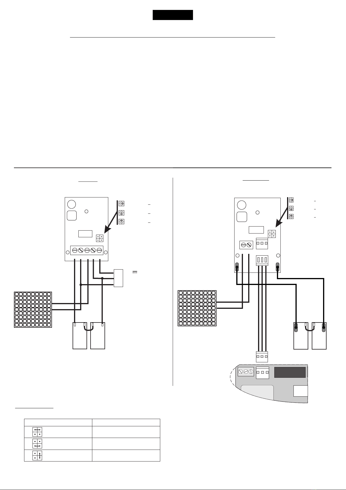
(BAT)
+
-
+
-
GND
PSOL
BAT 28VGND
CN1
+
-
S
+
GND
Solar Panel
Batteries
12V 12V
= charge 200mA
~
~
= charge 360mA
= charge 800mA
~
Code 23101105
Code 23101104
E SUN
E SUN Q
S 28VGND
CN1
+
GND
Solar Panel
PSOL
GND
+ Bat- Bat
= charge 200mA
~
~
= charge 360mA
= charge 800mA
~
USER 1
24V DG
MAXI
CNQ
+
-
+
-
Batteries
12V 12V
Note: To connect the User
1 24V DG MAXI control
u n i t w i t h q u i c k
connectable charger to an
old battery charger, you
must use the CNQ adapter
cable.
IMPORTANT: To connect the batteries, always use the battery charger.
CONNECTION OF BATTERIES TO BATTERY CHARGER CARD
28V Battery charger
Positive battery
Negative battery charger
Battery current (mA) Battery (Ah)
Insert two 12V batteries connected in series.
800
360
200
12 or 16
7
2
Specifications of
optional batteries:
24V Pb 1.2Ah min.
CN7
40
Other manuals for USER 1 - 24v DG R1
5
Table of contents
Other SEA Control Unit manuals

SEA
SEA USER 1 - 24v DG R1 User manual

SEA
SEA USER 1 - 24v DG R1 User manual

SEA
SEA GATE 1 DG R2BF User manual

SEA
SEA SLIDE NEW MAG User manual

SEA
SEA UNIGATE 1I User manual

SEA
SEA USER 2 24V DG ALL IN User manual

SEA
SEA Orion User manual

SEA
SEA GATE 1 DG R1 User manual

SEA
SEA SLIDE DG R2F User manual

SEA
SEA GATE 1 DG R1 User manual

SEA
SEA USER 1-24V User manual

SEA
SEA GATE 2 User manual

SEA
SEA SLIDE DG R2F User manual

SEA
SEA USER 2 24V DG R1B ALL-IN User manual

SEA
SEA GATE 2 DG R1B User manual

SEA
SEA GATE 2 User manual

SEA
SEA SWING 2 User manual

SEA
SEA 9521 User manual

SEA
SEA SWING 2 DG R2F User manual

SEA
SEA USER 1 - 24v DG R1 User manual


