Biosite Triage MeterPro User manual

Rev A I-1
Table of Contents
INTRODUCTION
How to Use This Guide. . . . . . . . . . . . . . . . . . . I-2
Introduction. . . . . . . . . . . . . . . . . . . . . . . . . . . . I-4
Description . . . . . . . . . . . . . . . . . . . . . . . . . . I-4
Unpacking. . . . . . . . . . . . . . . . . . . . . . . . . . . I-5
Specifications . . . . . . . . . . . . . . . . . . . . . . . . . . I-8
Test Device Specifications . . . . . . . . . . . . . . I-8
Warnings, Precautions and Limitations . . . . . . I-9
INSTALLATION
Installation . . . . . . . . . . . . . . . . . . . . . . . . . . . . N-1
Set Parameters . . . . . . . . . . . . . . . . . . . . . . . N-10
List of Programmable Parameters . . . . . . N-10
Supervisor Access . . . . . . . . . . . . . . . . . . N-10
How to Set Parameters: Basic Instructions
. . N-11
Meter Settings. . . . . . . . . . . . . . . . . . . . . . N-11
Communication Settings. . . . . . . . . . . . . . N-17
Clock . . . . . . . . . . . . . . . . . . . . . . . . . . . . . N-20
User ID ...........................N-21
Ranges ...........................N-24
Test Settings . . . . . . . . . . . . . . . . . . . . . . . N-25
QC Parameters . . . . . . . . . . . . . . . . . . . . . N-27
Bypass............................N-28
Install Code Chip®module . . . . . . . . . . . . . . N-29
OPERATION
Operation . . . . . . . . . . . . . . . . . . . . . . . . . . . . O-1
Run Test . . . . . . . . . . . . . . . . . . . . . . . . . . . . . O-2
Purpose. . . . . . . . . . . . . . . . . . . . . . . . . . . . O-2
QCDevice . . . . . . . . . . . . . . . . . . . . . . . . O-3
QC Sample . . . . . . . . . . . . . . . . . . . . . . . O-5
Patient Sample . . . . . . . . . . . . . . . . . . . . O-7
Recall Results . . . . . . . . . . . . . . . . . . . . . . . . O-10
Last Record. . . . . . . . . . . . . . . . . . . . . . O-10
Patient Results . . . . . . . . . . . . . . . . . . . O-11
QC Results . . . . . . . . . . . . . . . . . . . . . . O-16
Reagent Lots–QC . . . . . . . . . . . . . . . . . O-22
Archive Last Test. . . . . . . . . . . . . . . . . . O-22
Print all Results . . . . . . . . . . . . . . . . . . . O-23
Delete Results . . . . . . . . . . . . . . . . . . . . . . . . O-25
Display Backlight . . . . . . . . . . . . . . . . . . . . . O-27
Alpha Numeric Mode . . . . . . . . . . . . . . . . . . O-28
CARE & MAINTENANCE
Total Quality Assurance .................M-1
Service and Maintenance Procedures . . . . . . M-6
Troubleshooting . . . . . . . . . . . . . . . . . . . . . . . M-9
ReturnProcedure .....................M-12
APPENDIX
Glossary. . . . . . . . . . . . . . . . . . . . . . . . . . . . . . A-1
SoftwareFlowchart . . . . . . . . . . . . . . . . . . . . . A-3
Sample Log Sheets . . . . . . . . . . . . . . . . . . . . . A-4
Index of Page Revisions . . . . . . . . . . . . . . . . . A-8
Declaration of Conformity . . . . . . . . . . . . . . . . A-9

Rev AI-2
How to Use This Guide
This manual contains:
• Instructions for the operation and maintenance of the Triage®MeterPro, and;
• Basic instructions for testing samples
The Triage MeterPro software has been designed to provide the user step by step
instructions. The meter displays test results and menu options in the upper half of the meter
screen. In smaller letters at the bottom of each screen, the meter displays instructions
pertaining to the task being performed.
Note: To run
specific tests,
such as the Triage®
Cardiac Panel, you
also will need detailed
information contained
in the product-specific
package insert,
included in the test kit.
The display above is the Main Menu and
appears after the meter has been turned on
and completed an automatic self-test.

Rev A I-3
The Triage MeterPro User Manual is divided into five sections.
Section 1 – Introduction: Provides an overview of Triage MeterPro.
Section 2 – Installation: Guides the user through first time setup.
Section 3 – Operation: Guides the user through running tests, recalling results and
deleting results.
Section 4 – Care & Maintenance: Total Quality Assurance, Warnings, Precautions
and Limitations, Service and Maintenance, Warranty.
Section 5 – Appendix: Troubleshooting, Sample Log Sheets, Index of Page Revisions,
Certificate of Conformity, Software Flowchart, Glossary
Symbols Meter Keys are indicated by
=Caution = Up key = Down key
=Important = Left key = Right key
=Note =On/Offkey =Delete key
=New in Version A = Brightness key = Shift key
=Symbol key (used with Shift key)
=Print key = Paper Feed key
=Enter key =Exit key
Screen commands and options are indicated by ABOLDED FONT WITH SMALL CAPITAL LETTERS
At the bottom of each page appears the page number and revision. A page revision chart is
located in the appendix and will be revised and included whenever a manual update occurs.
Use the Page Revision Chart to periodically verify presence of all pages. You may receive
an updated copy of this chart at any time by calling our Customer Service Department at
1-888-BIOSITE (1-888-246-7483).

Rev AI-4
Introduction
Description
What is the Triage MeterPro?
The Triage MeterPro is a portable fluorescence instrument used to measure the results of
tests manufactured by Biosite®Incorporated. The Triage MeterPro can be used in a
laboratory or in a point-of-care setting.
The Triage MeterPro uses a Class 1 laser as a light source. Light from the laser hits a test
device that has been inserted in the meter. This causes the fluorescent dye in the test device
to give off energy. The more energy the fluorescent dye gives off, the stronger the signal.
Overview: Running a Test
After a test sample (for example, blood) from a patient is added to the test device, the
test device is inserted in the Triage MeterPro. The meter measures how much of the
substance (a particular protein marker) is present, based on standards that have been
pre-programmed into the meter.The patient identification, the User I.D. number and the
test results can be printed out on a paper tape.
Triage Test Devices. A test device holds the
sample and also contains the reagents and
other materials needed for the test.

Rev A I-5
Inaddition to testing samples from patients, the Triage MeterPro contains pre-programmed
Quality Control (QC) functions that allow the person operating the meter to monitor
quality control.
Unpacking
The Triage MeterPro and the items that come with it are provided in a single box.
Triage test devices are packaged separately and include instructions for running specific
tests. If you have any questions, contact Biosite Incorporated Technical Services
at 1-888-BIOSITE (1-888-246-7483).
Contents:
• Triage MeterPro
• QC Device & Code Chip®module (in the QC Device box)
• AC / DC Power Converter
• AA Batteries
• Rolls of Printer Paper (additional rolls are supplied in each box of test devices)
•Supervisor Code Chip module & Code Chip module Box
• Sticker with Technical Services Hotline Number
Note: The
Triage MeterPro
accepts test devices
that are designed
specifically for use
with the Triage
MeterPro. Please refer
toproduct-specific
package inserts
included in each
test kit for more
information.
Printer paper
located below
QC Device Box

Rev AI-6
Parts of the Triage MeterPro
Power button
Delete
Backlight
Test device insertion port
Thermal printer
Data port
Code Chip module port
Battery cover
Power supply port
Printer cover
LCD (liquid crystal display)
Printer cover

Rev A I-7
Power button Used to turn the Triage MeterPro on and off.
Print Button Used to print the test results or display screen.
Delete Button Used to delete data.
Enter Button Allows the operator to select menu items and acknowledge
alarm conditions.
Exit button Used to exit the displayed menu or eject the test device.
Keypad Used to enter identification numbers.
Arrow Buttons Used to toggle through menu items.
Thermal Printer Prints the test result on paper.
Data Port Connection point for the (optional) Bar Code Scanner,allowing
the operator to scan patient or user identification numbers instead
of manually entering numbers on the keypad. May also be used
to connect to a data management system/LIS.
Code Chip module Port Insertion point for Code Chip modules which contain lot / device
specific data for use in providing test results.
Power Supply Port Connection point for the supplied AC / DC Power Converter.
Printer Cover Cover, which when pulled straight up, reveals the paper roll.
LCD Screen The LCD (Liquid Crystal Display) Screen shows the menu of
possible tests and tasks and prompts the operator to take the
next step.

Rev AI-8
Specifications
Physical
Size 8.5” x 6.25 “x 2.75” (22.5 cm x 19 cm x 7 cm) D x W x H
Weight 1.5 pounds (0.7 kg) without batteries
Electrical
6vDC at 1 amp – supplied via 4 AA batteries or AC/DC Converter
Keypad Numeric with special function keys (22 total)
Environmental
Temperature 15C – 30C
Humidity 10% – 85%
Location Dry, clean, flat horizontal surface away from direct sunlight
Optical
Light Source Laser Diode – <1 milliwatt
Detector Silicone Photodiode
Memory Capacity
750 Patient Records 20 Reagent Lot Code Chip modules
200 QC Sample Results 30 QC Sample Code Chip modules
250 QC Device Results 4 QC Device Code Chip modules
600 User ID numbers
Miscellaneous
RS-232 computer interface port
Thermal Printer
LCD screen display
Options
• External Bar Code Reader (rapid entry of User, Patient or Auxiliary ID numbers).
• Triage Census®Data Management Software.
• Triage Census Data Management Software with LIS Connectivity.
Test Device Specifications
Test device specific information is provided in the applicable product insert. The
instrument analyzes immunoassay test devices manufactured by Biosite Incorporated.

I-9Rev A
•Operate the Triage MeterPro on a level, dry surface away from direct sunlight.
•The QC Device is light-sensitive and should be stored in its black opaque case when
not in use.
•Do not move the Triage MeterPro while a test is in progress.
•Ensure all sample fluids have absorbed into the test device prior to running the test to
prevent internal contamination of the meter.
•Use only the AC / DC power adapter provided with the Triage MeterPro. An identifying
tag has been placed on the cord for quick identification.
• Do not drop the Triage MeterPro.
•Do not place objects on the Triage MeterPro.
•Do not immerse the Triage MeterPro in water or any liquids.
Warnings, Precautions and Limitations

Rev AI-10
(Intentionally blank)

N-1Rev A
The Main Menu
1. Unpack Meter:
a. Remove the meter from the box and protective plastic bag.
2. Power Meter On:
Batteries
a. Turn the meter over.
b. Remove battery cover.
c. Install 4 AA batteries, paying attention to battery orientation in the battery
compartment.
d. Replace batterycover and turn meter right side up.
e. Power the meter on by pressing the key. Press the key to run self-test.
When the test is completed, the meter display screen will come to rest at the
main menu.
AC Power Supply
a. Remove the power supply from the box.
b. Plug one end into an AC outlet.
c. Plug the opposite end into the round hole in the back of the meter.
Installation
Note: The Low
Power Indicator
monitors the active
power source. To
verify adequate
batterypower:
•Navigate to the
Main Menu
• Remove the AC
power supply
• Press the EXIT key
(the meter attempts
to eject a device)
• Observe the Main
Menu on the
meter’s display.
Replace the batteries
if the power icon is
visible.
User instructions
Low Power Indicator
Menu items
Time and date

Rev AN-2
3. Install paper:
a. Remove the printer cover by pulling up on the cover as indicated by the arrow on
the back of the cover.
b. Tear or cut a clean, straight edge to feed into the printer. Do not cut paper at an
angle, as the printer must sense the edge of the paper along the feed path.
c. Position the paper such that the paper will feed from under the roll (as opposed to
over the top of the roll, see picture).
d. Insert the paper edge under the paper roller (platen) until it firmly seats or
resistance is felt.
e. Press the key twice, paper will feed through the printer and extend
out the meter.
f. Place the roll of paper into the paper compartment.
g. Replace the printer cover and continue operation.
Note: The
printer contains
apaper sensor and
will feed the new
paper roll only when
paper with a clean
straight line is
pressed into the
paper roller.
For more details
about Installing
Paper see the CARE &
MAINTENANCE section.

Rev A N-3
The Supervisor’s Main Menu
4. Insert Supervisor Code Chip module:
a. Remove the Supervisor Code Chip module Box from the meter box.
b. Remove the Supervisor Code Chip module from its box.
c. Insert the Supervisor Code Chip module into the Code Chip module Port. The port
is located on the left side of the meter, towards the bottom front corner. Note the
orientation of the Code Chip module in the drawing below.
d. Once the Supervisor Code Chip module is installed, verify that two additional menu
items appear on the display screen.
For more details about
Code Chips modules
see page N-29.
Code Chip module
Code Chip module Port
Menu options
accessible only
when the Supervisor
Code Chip module
is inserted.

Rev AN-4
For reference, record your settings in the space provided.
For more details about
Meter Settings see
page N-11.
5. To Change Meter Settings:
a. Select SET PARAMETERS using the keys and Press the key.
b. Select METER SETTINGS using the keys and Press the key.
c. Select ID SETTINGS, DISPLAY SETTINGS or COMM SETTINGS using
the keys and Press the key.
d. Select the desired setting using the keys and change the value of the
setting by using the keys.
ID SETTINGS Default Options New Setting
CHARACTERS USER ID Min 1 1-10
Max 10 1 - 10
CHARACTERS PAT.ID Min 1 1 - 12
Max 12 1 - 12
CHARACTERS AUXID Min 1 1 - 12
Max 12 1-12
AUX.ID ENABLE/DISABLE Disabled Disabled, Enabled
e. Press the key to save changes to ID Settings.

Rev B N-5
DISPLAY SETTINGS Default Options New Setting
LANGUAGE English Multiple
PRINT MODE Automatic Automatic, Manual
AUTO POWER-OFF2hour 1
/2hour, 1 hour, 2 hour,
4hour, None
DISPLAY CONTRAST 4 0 – 8
(8 = heaviest contrast)
PRINTER CONTRAST 4 0 – 8
(8 = heaviest contrast)
f. Press the key to save changes to Display Settings.
COMM SETTINGS Default Options New Setting
BAUD RATE 9600 9600, 38400
PAT. RESULT APPROVAL Enabled Enabled, Disabled
LIS ENABLE/DISABLE Disabled Disabled, Enabled
UPLOAD Manual Manual, Automatic
LIS PASSWORD
g. Press the key to save changes to Communication Settings.
h. Press the key to save changes to Meter Settings.
For reference, record your settings in the space provided.
For more details about
Communications,
including entry of a
Biosite provided, meter
specific password, see
page N-17.

Rev AN-6
6. Change Clock:
a. Select SET PARAMETERS using the keys and Press the key.
b. Select CLOCK using the keys and Press the key.
c. Select the HOUR : MINUTE area using the keys. Type in the correct time
using the number keys.
d. Press the key to move to AM or PM.
e. Select AM or PM using the keys.
f. Press the key to move to TIME FORMAT.
g. Select AM/PM or 24 HR. using the keys. If selecting 24 HR.,
the previously entered HOUR : MINUTE will change to a 24-hour format and
the AM or PM will disappear.
h. Press the key to move to the DATE.
i. Type in the 6-digit date according to the DATE FORMAT below it.
j. Press the key to move to the DATE FORMAT.
k. Select MM-DD-YY, DD-MM-YY or YY-MM-DD using the keys.
The previously entered DATE changes as the DATE FORMAT changes.
l. Press the key to save changes.
Setting Default Options New Setting
TIME FORMAT AM / PM AM / PM; 24HR.
DATE FORMAT MM-DD-YY MM-DD-YY,
DD.MM.YY,
YY-MM-DD
7. Set User ID:
The Triage MeterPro normally requires a User ID to be entered prior to a patient test or
aQC test. Refer to page N-21 for instructions. Alternately, this feature may be
bypassed. See page N-8.
For more details about
Clock Settings see
page N-20.

Rev A N-7
8. Change Reference Ranges / Thresholds for Tests:
a. Select SET PARAMETERS using the keys and Press the key.
b. Select RANGES using the keys and Press the key.
c. Select the test panel type using the keys.
d. Select the analyte and level using keys. Type in the new value for
the HIGH or LOW cutoff as appropriate.
e. Press the key to save changes.
9. Change QC Parameters:
a. Select SET PARAMETERS using the keys and Press the key.
b. Select QC PARAMETERS using the keys and Press the key.
c. Select the desired setting using the keys and change
the value to the right of the setting by using the keys.
Setting Default Options New Setting
QC DEVICE FREQ.Daily None, 8HR, Daily,
Weekly,Monthly
QC SAMPLE FREQ.Monthly None, 8HR, Daily,
Weekly, Monthly
NUMBER OF CONTROLS 21or 2
d. Press the key to save changes to QC Parameters.
For more details
about Ranges Settings
see page N-24.
For more details about
QC Parameters Settings
see page N-27.
Note: The lowest
value of the
Range or Threshold
may be disabled for
some test panels. Refer
to the appropriate
Product Insert for
specific information.

Rev AN-8
10. Change Bypass settings:
a. Select SET PARAMETERS using the keys and Press the key.
b. Select BYPASS using the keys and Press the key.
c. For USER ID select ON or OFF using the keys.
d. Press the key to save changes to the Bypass setting.
11. Prior to commencing patient testing, remove the Supervisor Code Chip module
from the meter, return it to the storage box and place in a safe place for future
use.
The meter is now ready to run QC Tests in preparation for Patient Testing.
QC Testing should be performed in the following manner:
1. Run QC Device (see page O-3).
2. Run QC Sample for each lot of devices (see page O-5).
3. If appropriate, Run Calibration Verification Set as a patient sample for each test
panel type to be used. (Refer to the applicable ProcedureManual and Calibration
Verification Set Package Insertfor detailed instructions).
Location
The Triage MeterPro should be placed on a dry, clean, flat, horizontal surface away
from direct sunlight.
Power
The Triage MeterPro requires 6-volts DC supplied by either AC or DC. The meter will run
approximately 100 tests on batteries. It is recommended to use batteries as a backup
in the event of a power outage.
CAUTION:Use only the power supply provided with the meter, failure to do
so may cause permanent damage to the meter.
For more details about
Bypass Settings see
page N-28
Note: If the
bypass is
ON
,
the user ID feature is
disabled and anyone
may run a test.
If the bypass is
OFF
,
the user ID feature is
active and only
authorized users may
run a test.
To Install User ID
numbers, see
page N-21.
Note: The Triage
MeterPro will
automatically
turnoff if left unused
for 2 hours, unless
programmed
otherwise by the
supervisor. Optional
settings allow
automated turnoff
after 1
/2hour, 1 hour,
2hours, 4 hours or
NONE.
N-9Rev A
Self-Test
The Triage MeterPro checks the system to verify it is operating properly by running
self-tests when powered on and prior to each test.
•Power On –includes laser operation, internal standard range, battery power,
and software verification.
•Each Test –verifies the laser operation, internal standard range and battery power.
Code Chip modules
Meter data is updated via a disposable Code Chip module. The Code Chip module
contains microchip circuitry embedded into a plastic housing. When inserted into the
meter Code Chip module port and activated, the information is transferred into the Triage
MeterPro’s memory. A Code Chip module typically needs to be installed only once and
remains in the meter memory. A Code Chip module does not need to remain in the meter
while performing tests.
There are five types of Code Chip modules which can be distinguished by shape or color.
•Reagent Test Code Chip module–included in each box of test devices; contains
calibration, expiration date and other data about the device lot. (Color varies by test
type.)
•QC Sample Code Chip module –included in each box of QC Sample; contains
expiration date and other data about the QC Sample lot including acceptable range.
(Color varies by test type.)
•QC Device Code Chip module –included in the black QC Device box (comes with
the Triage MeterPro); contains data about how the meter should read its matching
QC Device. (Dark gray.)
•Supervisor Access Code Chip module –included with each Triage MeterPro;
contains code to activate Supervisor functions. (Light gray.)
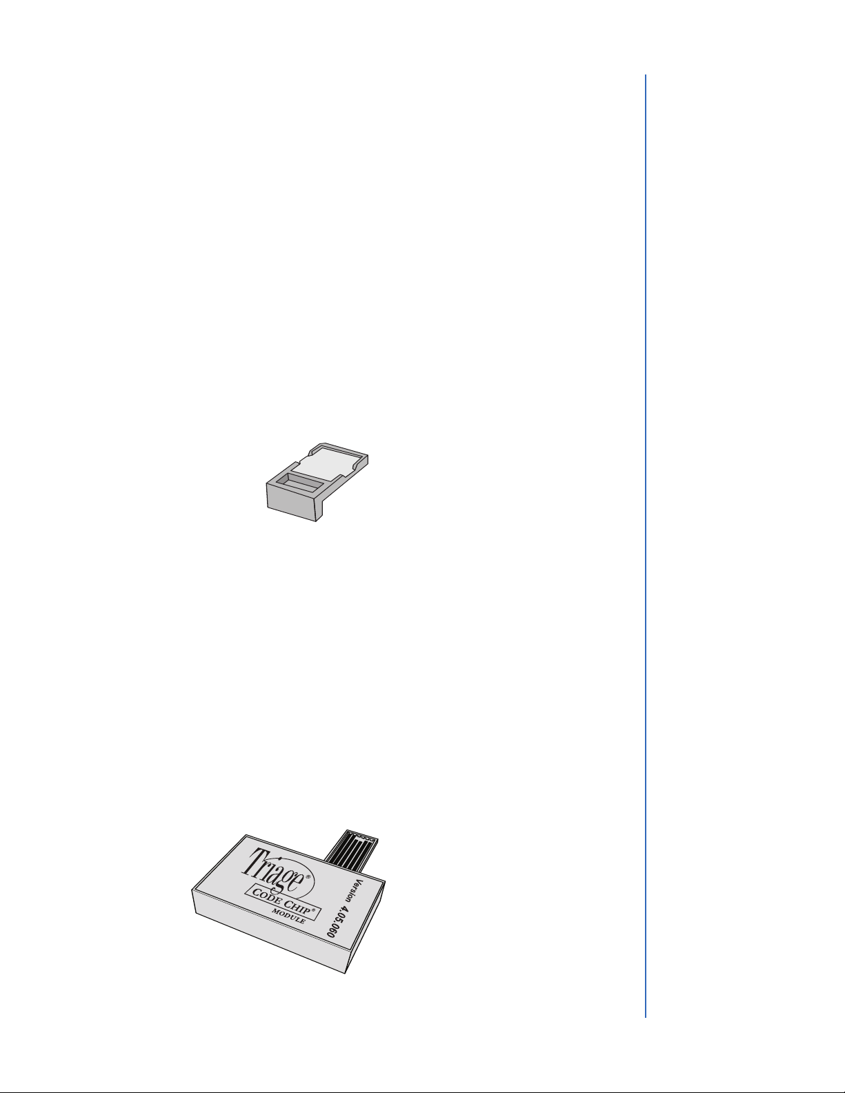
•SoftwareUpgrade Code Chip module –provided when Triage MeterProsoftware
upgrades areavailable; contains new softwarefor the meter.
Software Upgrade Code Chip module
Standard Code Chip module

Rev BN-10
Set Parameters
Code Chip module
Code Chip module Port
Purpose
The SETPARAMETERS function allows the supervisor to select a number of settings.
Access to these settings is controlled using the Supervisor Code Chip module.
List of Programmable Parameters
Asupervisor can set the following parameters:
Heading Parameters
METER SETTINGS
ID SETTINGS Number of Characters in User ID, Number of Characters
in Patient ID, Number of Characters in Auxiliary ID,
Enable or Disable Auxiliary ID
DISPLAY SETTINGS Language, Printer Mode, Auto Power-Off, Display Contrast,
Printer Contrast
COMMUNICATIONS Enable or Disable LIS, Baud Rate, Auto or Manual Upload,
Result Approval
CLOCK Time, Date, and Display Format
USER ID Add New User ID, Update User ID, Delete User ID
or User ID List
RANGES Test Cutoffs
TEST SETTINGS Block Analytes, Display Mode
QC PARAMETERS Minimum frequency for QC Tests, number of controls
BYPASS Disable User ID requirement
Supervisor Access
ASupervisor Code Chip module is shipped with each meter.Installing the Code Chip
module gives the supervisor access to the SET PARAMETERS and DELETE RESULTS
function.
Toinsert the Supervisor Code Chip module into the Triage MeterPro, slide the chip labeled
"SPR" into the meter’s Code Chip module port as shown in the picture.
Other manuals for Triage MeterPro
1
Table of contents
Other Biosite Medical Equipment manuals


