Biotage Flash 75 User manual

Biotage®Flash 75/150
User Manual

Biotage®Flash 75/150 User Manual | © Biotage 2018
Contents
Biotage®Flash /
User Manual
CONTENTS
Introduction
1 Speed
1 Safety
1 Performance
System Components
2 Prepacked Biotage®Flash Cartridge
2 Radial Compression Module
3 AM-190 Manifold
4 Solvent Reservoir
4 Sample Injection Module (Biotage®SIM) Kit
5 Grounding Kit
5 Start-Up Kit
5 Cartridge Extraction Tool
6 Chemical Resistance
Safety
7 Intended Use
7 Education, Training, and Competence
7 Warranty and Liability
7 Service
7 Labels
7 Safety Requirements
Installation
9 Set Up the Radial Compression Module
9 Set Up the AM-190 Manifold
9 Set Up the Sample Injection Module (Biotage®SIM)
10 Set Up the Solvent Reservoir
10 Attach the Inert Gas Supply and Solvent Lines
12 Ground the System
How to Use the system
14 Fill the Solvent Reservoir
14 Insert a Flash Cartridge
15 Pressurize the Radial Compression
Module and the Solvent Reservoir
15 Equilibrate the Cartridge
16 Load Sample and Collect Fractions
18 Refill the Solvent Reservoir
18 Empty the Solvent Reservoir
18 Depressurize the Radial Compression Module
and Remove the Used Cartridge
19 Clean the Sample Injection Module (Biotage®SIM)
Troubleshooting
20 AM-190 Manifold
20 Biotage®Flash 75/150 Radial Compression Module
21 Operation
21 Sample Injection Module (Biotage®SIM)
21 Solvent Reservoir
Optimizing Flash Separations
22 Column Separations are Governed by CV, not Rf
22 Vary Solvent Strength to Maintain
RfValues Between 0.15 and 0.40
23 Vary Solvent Selectivity to Maintain
RfValues Between 0.15 and 0.40
24 The Relationship Between the Size of a Column
and the Sample Load is Dependent on CV
Flash Chromatography Workbook
General Information
31 Price List and Ordering Information
31 Download User Documentation
31 Manufacturer
31 Contact Us
Notes
Introduction
Introduction
Biotage®Flash 75 and Biotage®Flash 150 are flash purification
systems based on prepacked cartridge technology that provide
users of traditional self-packed glass columns with three critical
operational benefits: speed, safety, and performance.
Speed
Unlike glass columns, which operate at low pressure and
have very poor flow distribution, Biotage flash cartridges are
optimized for high speed separations. Purifications that might
otherwise have used up half a working day can be run in 15 to
45 minutes. For a chemist running just a single reaction and
separation per day, the annual gain in productivity can be as
high as 15 additional weeks each year; time that could be used
to develop new compounds or processes. With the rising cost
of labor, the efficiencies afforded by this alone can exceed the
cost of the flash system and a year’s supply of cartridges.
Safety
Laboratory and process safety is a growing concern with
many companies carefully reviewing current procedures and
techniques to reduce the risk of chemical exposure, injury, and
consequently their liability. Biotage Flash systems eliminate the
concerns of using glassware under pressure by utilizing durable
polyethylene cartridges that are prepacked and completely
self-contained, eliminating user exposure to silica dust, HP-API,
or any contaminants left after a separation.
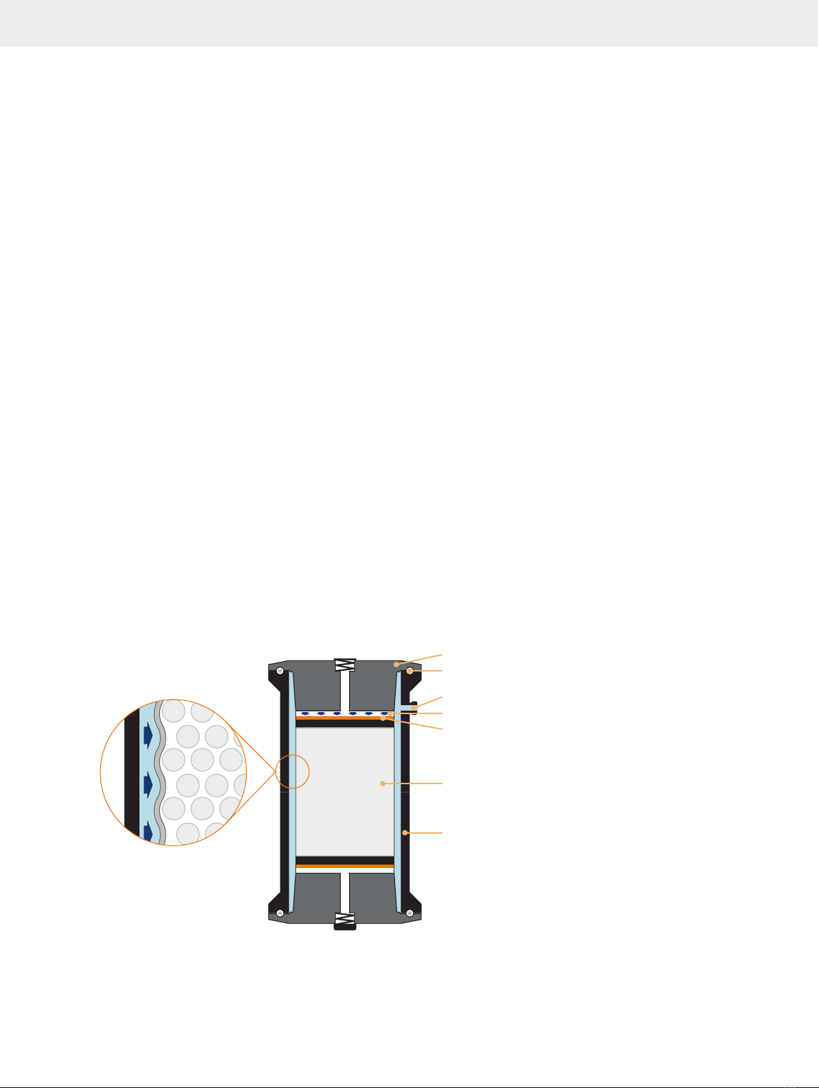
Figure 1.Biotage patented radial compression technology improves flash separation performance and increases separation speed.
Distribution plate (only Flash 75)
O-ring
10 µm porosity frit
Prepacked, disposable flash cartridge
Compression barrel
Radial compression inert gas supply
316 stainless steel head
External
pressure
applied
Media
Performance
In addition to speed and safety, Biotage flash cartridges improve
both the performance and the reproducibility of separations.
The use of Biotage patented radial compression technology (see
Figure 1) reduces interstitial spaces (void volume) within the
packed bed. The optimized bed density means that compounds
are collected in narrow bands, which results in higher separation
efficiency. Unlike glass columns, each Biotage flash cartridge
will perform in the same way, time after time.
Flash 75/150 systems include everything you need to separate
compounds in a fume hood with standard laboratory mounting
bars, clamps, and an inert gas such as nitrogen. A typical
Flash 75/150 system can be assembled in minutes and be ready
to run samples in less than an hour.
Biotage®Flash 75/150 User Manual | © Biotage 2018
System Components
System Components
Prepacked Biotage®Flash Cartridge
The prepacked flash cartridge from Biotage is the key to the
radial compression module’s improved performance. Flash
cartridges are available in a wide variety of sizes for optimum
separation of samples ranging from 50 mg to 8 kg. Biotage
offers Flash 75 and Flash 150 cartridges and radial compression
modules for samples up to 1000 grams; see Table 1 below.*
Each flash cartridge is prepacked as standard with normal
phase silica, C18-bonded silica, amine-functionalized silica,
or activated carbon, and is individually wrapped with a water
repelling plastic film to minimize water vapor adsorption.
Each case of cartridges includes certificates of compliance and
conformance with detailed information for your records in GLP
or cGMP environments.
The flash cartridge itself is made from FDA compliant, medium
density polyethylene. The flow distribution plate and 10 m
porosity frits are also fabricated from FDA compliant polyethylene.
*This user manual deals specifically with the Flash 75 and 150 cartridge
series. For information on additional cartridge diameters, contact Biotage.
See contact information on the back of this document or visit our website
www.biotage.com.
Radial Compression Module
The radial compression module (see Figure 3), together with
the flash cartridge, is the heart of the system. It is an anodized
aluminum barrel with an instant-tight fitting for connection to
the inert gas outlet on the AM-190 manifold (see page 3).
The safety features on the barrel include a safety relief valve that
activates at pressures in excess of 110 psi (7.6 bar) for Flash 75
and 150 psi (10.3 bar) for Flash 150, and a red pressure indicator
that sticks out when there is more than 20 psi (1.4 bar) of inert
gas pressure inside the radial compression module (see Figure 2).
Figure 2.The pressure indicator sticks out when the pressure inside the
radial compression module is more than 20 psi (1.4 bar).
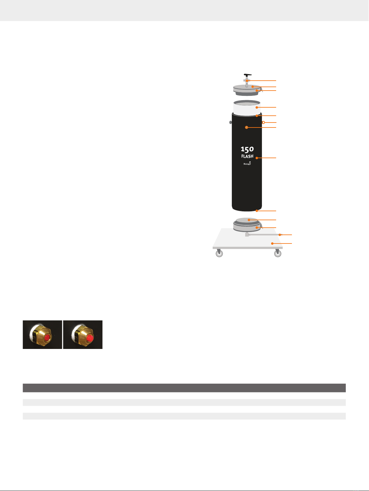
Figure 3
Safety relief valve
Viton O-ring
Anodized aluminum barrel
Pressure indicator
Radial compression inert gas inlet
Stainless steel head assembly
Fraction collection outlet
Portable cart
(only Flash 150)
V-band clamp
V-band clamp
Stainless steel head assembly
Three-way valve
Prepacked cartridge
Viton O-ring
.The components of the Flash 150 radial compression module.
The Flash 75 module has the same features but instead of being delivered
with a portable cart it has mounting pads on the side of the barrel for easy
connection to lab scaffolding or support bars.
A Viton O-ring sits inside a groove in the top lip of the barrel and
seals the radial compression module against leakage of gas.
The bottom opening of the barrel has an identical groove and
O-ring. Two replacement O-rings are provided with the start-up
kit (see page 5).
The Flash 150 radial compression module comes with a portable
cart with casters. The Flash 75 barrel is easily attached to standard
½" (12.7 mm) Flex-Frame type laboratory mounting bars using
a pair of standard mounting rods that screw into the mounting
pads on the side of the barrel. With the rods in place, the module
can be secured with standard mounting clamps (not included).
Specification Flash 75M Flash 75L Flash 150M Flash 150L
Size D x H 75 x 150 mm (3" x 6") 75 x 300 mm (3" x 12") 150 x 300 mm (6" x 12") 150 x 600 mm (6" x 24")
Mass of Biotage®KP-Sil Silica (approx.) 0.4 kg 0.8 kg 2.5 kg 5.0 kg
Column Volume (approx.) 0.5 liter 1.0 liter 4.3 liters 8.6 liters
Sample Size Up to 80 grams Up to 160 grams Up to 500 grams Up to 1000 grams
Table 1.The specifications of the Flash 75 and Flash 150 cartridges.
System Components
Head Assemblies
Two stainless steel head assemblies, with knife-edges for
sealing the cartridge, attach to the top and bottom of the barrel
by means of V-band clamps, which can be easily hand-tightened
to seal the flash cartridge inside the barrel. The top head
assembly is fitted with a three-way valve that connects to the
solvent reservoir and the outlet of the Biotage sample injection
module (Biotage®SIM). The bottom head assembly has a tube
compression fitting; this is the fraction collection outlet of the
radial compression module.
AM- Manifold
The AM-190 manifold (see Figure 4) regulates the radial
compression pressure and the flow of sample and solvent into
the radial compression module. The manifold is easily attached
to standard fume hood mounting bars using the two mounting
rods supplied with the manifold; see “Set Up the AM-190
Manifold” on page 9.
The AM-190 manifold comes equipped with the following
features. See the corresponding letters in Figure 4.
A. An inlet for pressurized inert gas, with an instant-tight fitting
for attaching tubing.
B. A safety relief valve that activates at pressures in excess of
150 psi (10.3 bar).
C. A locking pressure regulator (labeled PRR-01), with a water
trap (C2), for increasing or decreasing the inert gas pressure
to the radial compression module.
D. A pressure gauge (labeled PG-01) for monitoring the inert
gas pressure delivered to the radial compression module.
E. A valve (labeled MV-01) for turning the flow of compressed
inert gas to the radial compression module on or off (see
Table 2), with an instant-tight fitting for attaching tubing (E2).
F. A locking pressure regulator (labeled PRR-02) for increasing
or decreasing the inert gas pressure to the solvent reservoir
and sample injection module (SIM).
G. A
pressure
gauge (labeled
PG-02)
for monitoring the inert
gas pressure delivered to the solvent reservoir and SIM.
H. A valve (labeled MV-03) for turning the flow of compressed
inert gas to the SIM on or off (see Table 2), with an instant-
tight fitting for attaching tubing (H2).
I. A valve (labeled MV-02) for turning the flow of compressed
inert gas to the solvent reservoir on or off (see Table 2), with
an instant-tight fitting for attaching tubing (I2).
Valve Positions
Valve Off/Vent On/Pressurize
MV-01
PRR-01
BIOTAGE
®
FLASH 75/150
CHROMATOGRAPHY
AM-190 MANIFOLD
PRR-02
MV-01
PG-01 PG-02
MV-03 MV-02
N
2
N
2
N
2
A B
PRR-01
BIOTAGE
®
FLASH 75/150
CHROMATOGRAPHY
AM-190 MANIFOLD
PRR-02
MV-01
PG-01 PG-02
MV-03 MV-02
N
2
N
2
N
2
A B
MV-02 and
MV-03
PRR-01
BIOTAGE
®
FLASH 75/150
CHROMATOGRAPHY
AM-190 MANIFOLD
PRR-02
MV-01
PG-01 PG-02
MV-03 MV-02
N
2
N
2
N
2
A B
PRR-01
BIOTAGE
®
FLASH 75/150
CHROMATOGRAPHY
AM-190 MANIFOLD
PRR-02
MV-01
PG-01 PG-02
MV-03 MV-02
N
2
N
2
N
2
A B
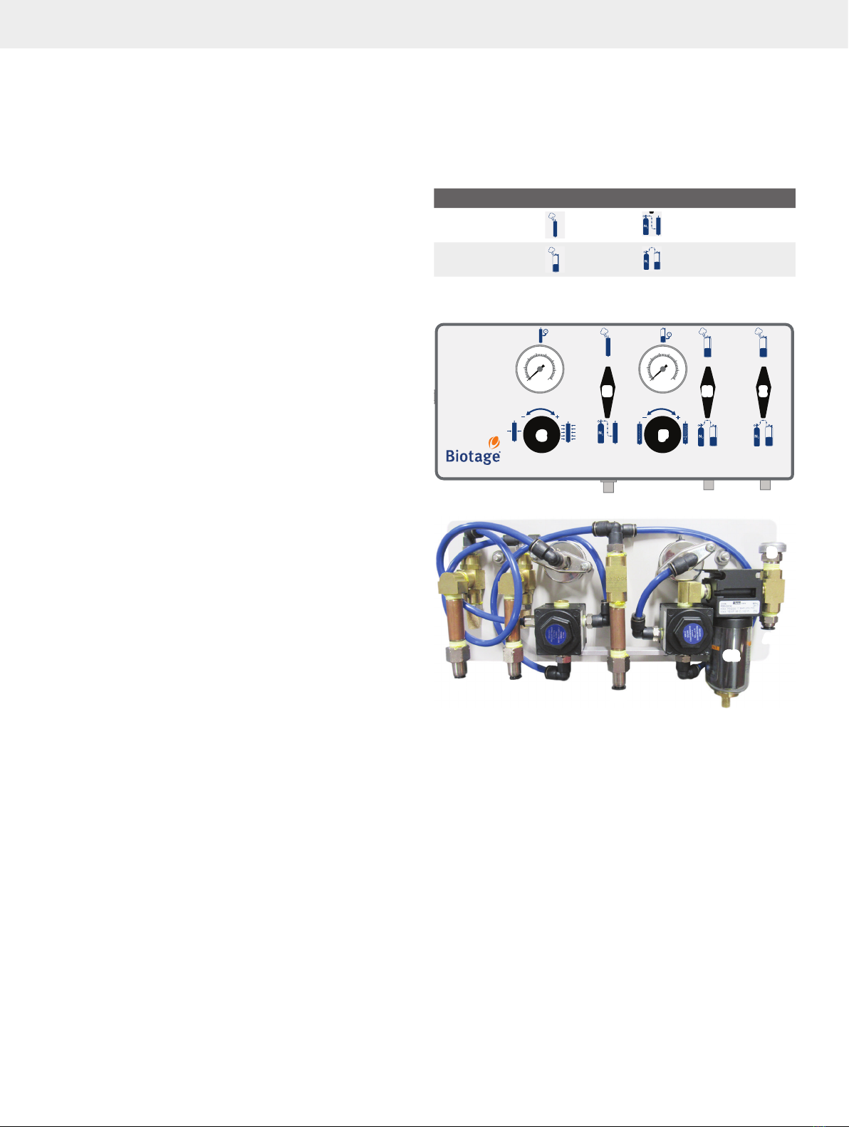
Table 2.The positions for the three valves on the AM-190 manifold.
Figure 4
PRR-01
BIOTAGE®FLASH 75/150
CHROMATOGRAPHY
AM-190 MANIFOLD
PRR-02
MV-01
PG-01 PG-02
MV-03 MV-02
N2N2
N2
A B
E H I
C F
A
C2
B
D G
E2
I2 H2
.The AM-190 manifold (bottom) regulates the flow of inert gas
into the radial compression module, solvent reservoir, and sample
injection module (SIM). The front panel of the AM-190 manifold (top) offers
easy-to-use switches to set all flows.
A = pressurized inert gas inlet, B = safety relief valve, C = regulator
for the gas pressure to the radial compression module, C2 = water
trap, D = gauge for the pressure delivered to the radial compression
module, E = compress/vent valve for the radial compression pressure,
E2 = instant-tight fitting for connecting a gas tube between the manifold
and the radial compression module, F = regulator for the gas pressure
to the solvent reservoir and sample injection module (SIM), G = gauge
for the inert gas pressure delivered to the solvent reservoir and SIM,
H = compress/vent valve for the solvent pressure, H2 = instant-tight
fitting for connecting a gas tube between the manifold and the solvent
reservoir, I = compress/vent valve for the SIM pressure, and I2 = instant-
tight fitting for connecting a gas tube between the manifold and the SIM.

Biotage®Flash 75/150 User Manual | © Biotage 2018
System Components
Solvent Reservoir
Biotage provides an electropolished 316 stainless-steel solvent
reservoir, available in a 12-liter capacity for the Flash 75 system
and 37-liter and 60-liter capacities for the Flash 150 system.
The solvent reservoir is fitted with an instant-tight fitting for
pressurized inert gas, an on/off valve for solvent flow, and
a safety relief valve that activates at pressures in excess of
109 psi (7.5 bar).
The oval lid of the reservoir is fitted with a clamp that screws
shut, and has a solvent proof, PTFE-encapsulated Viton O-ring
to seal the lid in place. See “Set Up the Solvent Reservoir” on
page 10 for safety precautions on how to secure the lid once
the reservoir has been filled with solvent.
Figure 5
Fitting for
inert gas
On/off valve
Safety relief
valve
Lid with clamp
.The 60-liter solvent reservoir with the two-way valve open.
Sample Injection Module (Biotage®SIM) Kit
Biotage provides a sample injection module (SIM) kit, available
in 500 mL, 1000 mL, and 2000 mL sizes, to simplify the handling
of routine samples as well as viscous oils and samples with
poor solubility that need to be adsorbed directly onto silica.
SIM 500 is optimized for Flash 75M and 75L, SIM 1000 for
Flash 150M, and SIM 2000 for Flash 150L.
Illustrated in Figure 6, the SIM body is constructed of a welded
316 stainless steel tube with a sanitary clamp at the top and a
stainless steel 1/8" (Flash 75) or 1/4" (Flash 150) tube fitting at
the bottom. The top lid comes with a three-way valve. One port
supplies inert gas to drive liquid sample onto the cartridge.
The other port supplies solvent through the SIM when using a
pre-adsorbed sample loading technique.
The SIM is supplied with six sanitary gaskets (two of each type,
see “Sanitary Gaskets” below), one chain clamp (P/N 01520),
25 top frits (P/N FTF-0225), 25 bottom frits with sealing rings
(P/N FBS-1025), and one frit insertion tool (P/N 01596 for
SIM 500 and 1000 and P/N 03339 for SIM 2000).
Figure 6
Three-way valve
Solvent flow
Inert gas
Sanitary
clamp
Frit holder
316 stainless
steel tube
Pour in liquids, oils,
or coated samples
To the radial compression module
Nut
.The sample injection module (SIM) simplifies the handling of
routine samples as well as viscous oils and samples with poor solubility.
Sanitary Gaskets
The SIM includes three different types of sanitary gaskets;
PTFE/EPDM, Viton, and EPDM (see Figure 7). Biotage recommends
the black and gray PTFE/EPDM gasket for most applications, as
it is resistant to most normal phase solvents and mixtures. The
gasket is moderately soft and seats when the sanitary clamp is
firmly tightened. The PTFE/EPDM gasket may leak a small amount
of solvent initially if the SIM is completely full of liquid.
The black Viton and EPDM gaskets are very compressible and
will seal reliably up to 100 psi (6.9 bar), even with a finger-tight
sanitary clamp. EPDM, which has a green color dot on the edge,
is resistant to polar solvents but will swell in many common
aliphatic and aromatic solvents. Viton, which has yellow and
white color dots on the edge, is resistant to non-polar solvents,
but will swell in the typical polar modifiers. For solvent
compatibility information, see Table 3 below.
Solvent PTFE/EPDM Viton EPDM
Hexane FAIR GOOD POOR
Toluene GOOD GOOD POOR
Ethyl acetate GOOD POOR GOOD
Dichloromethane FAIR FAIR FAIR
Methanol GOOD POOR GOOD
Table 3.Solvent compatibility.
Table 3 shows a limited number of commonly used solvents.
To check the compatibility of a particular solvent or solvent
mixture, soak a gasket in the solvent/mixture for one hour and
then inspect it for swelling. If the gasket swells in use, allow
it to dry out in a fume hood until it returns to its normal size

System Components
(typically overnight). Perform a periodic check of your gaskets
and replace a gasket that shows sign of wear or damage or that
leaks at your typical operating pressures.
Figure 7.There are three sanitary gaskets for the SIM: 1) the black and
gray PTFE/EPDM gasket (P/N 415891SP), 2) the black Viton gasket with
yellow and white color dots on the edge (P/N 01615), and 3) the black
EPDM gasket with green dots on the edge (P/N 01616).
Grounding Kit
The system can build up high static charges as non-polar
solvents flow through PTFE tubing, membrane filters, and/or
across a bed of dry silica. To eliminate any risk of a static
discharge, the systems and ancillary containers must be
grounded before use.
The pre-wired grounding kit that is supplied with the system
includes a complete wiring harness assembly (see Figure 8)
and a pair of fraction collection assemblies (a smaller one for
the Flash 75 system and a larger one for the Flash 150 system,
see Figure 9). For instructions on how to install the grounding
kit, see “Ground the System” on page 12.
Figure 8.The wiring harness assembly included in the grounding kit.
Figure 9.The fraction collection assembly for the Flash 75 system (left)
and the Flash 150 system (right).
Start-Up Kit
Biotage provides a start-up kit consisting of the following items:
»
For supplying inert gas, the kit includes four (4)
six-foot lengths (1830 mm) of polyethylene tubing,
1/4" O.D., 0.04" wall thickness, color-coded
in BLUE (P/N 01487), YELLOW (P/N 01354),
GREEN (P/N 00547), and RED (P/N 00546).
»
For supplying solvent, the kit includes:
»
Flash 75: one (1) three-foot (914 mm) and one (1)
one-foot length (305 mm) of 1/8" O.D. CLEAR PTFE tubing
(P/N 00088), and one (1) six-foot length (1830 mm)
of 1/4" O.D. CLEAR PTFE tubing (P/N 00089).
»
Flash 150: one (1) twelve-foot length (3658 mm)
of 1/4" O.D. CLEAR PTFE tubing (P/N 00089).
»
Two (2) spare O-rings for the radial compression module
(P/N 00778 for Flash 75 and P/N 01420 for Flash 150).
»
One (1) two-part inert gas supply fitting, a 3/8" NPT
reducing bushing with a 1/4" (M) NPT attached to
an instant-tight tubing connector (P/N 03072).
»
One (1) three-way valve for the radial
compression module (P/N 04562).
»
One (1) grounding kit (P/N FGD-15075).
»
One (1) cartridge extraction tool (P/N 02131 for
Flash 75 and P/N 01428 for Flash 150).
»
Two (2) disposable 10 mL syringes (P/N 01656).
»
One (1) Luer injection port (P/N02838). Only Flash 150.
»
One (1) user manual (P/N 02140).
For detailed information on how tubing and fittings are attached
and assembled, refer to the section “Installation” on page 9.
Cartridge Extraction Tool
A cartridge extraction tool is provided to simplify the removal of
used flash cartridges from the barrel of the radial compression
module. The tool consists of a machined stainless steel rod with
a handle on one end and two swinging, bladed “leaves” on the
other (see Figure 10). A sliding ring on the shaft locks the leaves
into a position perpendicular to the shaft of the tool.
Figure 10
Sliding
lock ring
Bladed
“leaves”
.The cartridge extraction tool simplifies the removal of a used
cartridge from the radial compression module.
To use the tool, slip the lock ring to the bottom of the shaft so
that the leaves are held in place. Hold the tool by the handle
and push the tool firmly into the top of the cartridge. The bladed
surface of the leaves will “bite” into the plastic edge of the
cartridge, allowing it to be easily pulled out. Moving the sliding
lock ring up will release the leaves so the tool can be removed.

Biotage®Flash 75/150 User Manual | © Biotage 2018
System Components
Chemical Resistance
The following chemicals can be used in the wetted parts of the
system:
»
Acetone
»
Dichloromethane (methylene chloride, DCM)
»
Toluene
»
Acetonitrile (MeCN)
»
Tetrahydrofuran (THF)
»
Triethylamine (TEA)
»
N,N-dimethylformamide (DMF)
»
Ethyl acetate (ethyl ethanoate, EtOAc)
»
N-methyl-2-pyrrolidone (NMP)
»
Dimethylsulfoxide (DMSO)
»
Ethanol (EtOH)
»
Methanol (MeOH)
»
2-propanol (isopropanol, IPA)
»
Formic acid (methanoic acid, HCOOH)
»
Acetic acid (Ethanoic acid, HOAc, AcOH)
»
Deionized water (H2O)
»
Trifluoroacetic acid (TFA), max 5 % (by volume)
»
n-Heptane
»
Piperidine (pip)
»
Pyridine (pyr)
»
Ammonia (NH3) conc. 23–27 % (by weight)
»
tert-Butyl methyl ether (TBME)
»
Diethyl ether
»
10 mM phosphate buffered saline, pH= 7.4
»
50 mM phosphate-citrate buffer, pH= 5.0
»
Boric acid/NaOH/KCl buffer, pH=11
Note: The sample injection module (SIM) is delivered with three
types of sanitary gasket. Always check the gaskets' compatibility
with the solvent or solvent mixture that you want to use. For more
information, see “Sanitary Gaskets” on page 4.

Safety
Intended Use
Biotage Flash 75 and Flash 150 systems are intended solely
for purification. The systems must be operated in a laboratory
environment with an ambient temperature between 4°C and
32°C (39°F and 90°F) by trained professiona
ls. The system must
not be installed or used near a potential ignition source. It is the
responsibility of the customer to classify (zone) their particular
environment in order to verify that it meets the requirements of
the directive 1999/92/EC. All operations must be performed:
»
According to the user documentation
delivered with the system.
»
According to instructions available at www.biotage.com.
»
According to instructions given by the
technical support staff from Biotage.
»
Within limits set by the system’s technical specification and
in line with user standard operating procedures (SOPs).
Failure to follow those instructions and operate within the limits
set by the technical specification may result in personal injury
and/or equipment damage.
Education, Training, and Competence
It is your responsibility to provide all applicable health and
safety regulations to your personnel. You must also ensure that
all personnel involved in the operation and maintenance of the
system fulfill the following criteria:
»
Have the necessary education, training, and competence
required for the intended use of the system.
»
Observe general and specific safety regulations for the
use of the system and its accessories at all times in order
to reduce the risk of personal injury, fire, and explosion.
Warranty and Liability
See the “Biotage Terms & Conditions of Sale” document at
www.biotage.com.
Service
All service must be performed by an authorized Biotage service
engineer. Before handing over the system for service, it should
be emptied of all liquid and cleaned from harmful residues.
It is the responsibility of the customer to inform
Biotage®1-Point Support™
representatives if the system has been
used with hazardous biological, radioactive, or toxic samples
and/or solvents, prior to any service being performed.
If returning equipment to Biotage, this should be done in
accordance with the material return procedures supplied
separately by Biotage.
Only genuine Biotage spare parts must be used in the system.
Labels
Labels used on the system:
In accordance with all the essential requirements of
all applicable European product directives; see the
Declaration of Conformity.
In accordance with the ATEX Product Directive,
2014/34/EU for Group II, Category 2G equipment.
The equipment is intended for use in areas in which
explosive atmospheres caused by gases, vapors, or
mists or air/dust mixtures are likely to occur.
Manufacturer.
Consult accompanying user documentation.
Note: The system is ASME rated and in accordance with both
U.S. and Canadian safety standards.
Safety Requirements
You must observe all safety requirements when installing and
operating the system. Failure to install or use the system in
a manner specified by Biotage may result in personal injury
and/or equipment damage.
If the system has been damaged or does not function
properly, turn off the inert gas supply, depressurize the radial
compression module and the solvent reservoir, and contact
Biotage 1-Point Support (www.biotage.com).
Installation
»
The system must be unpacked and installed
as described on page 9.
»
Follow regional safety practices when handling
and moving shipping boxes and containers,
and when moving the system.
»
The total weight of the package including the
system is between 16 and 84 kg (35 and 185 lbs)
depending on the system configuration. Use suitable
lifting equipment when moving the package.
Safety

Biotage®Flash 75/150 User Manual | © Biotage 2018
Safety
»
The system must be placed in a well-ventilated fume hood
or an equivalent enclosure that is capable of exhausting
2.5 m3/min (90 ft3/min). Follow local and national safety
regulations for installing a system inside a fume hood and the
safety regulations supplied by the fume hood manufacturer.
»
Never install or use the system near
a potential ignition source.
»
The system, when operated with non-polar solvents
such as hexane, methylene chloride, etc., can build up a
high static electricity charge, which in certain conditions
can be dangerous. To eliminate any risk of a static
discharge, the systems and ancillary containers must
be grounded before use as described on page 12.
Failure to follow these grounding instructions may result
in equipment damage, personal injury, or death.
»
A trained person must verify that the system and
ancillary containers are grounded before each run.
Nominal resistance must be below 5 Ohm between
ground and each metal point in the system.
»
Always connect inert gas such as nitrogen to
the gas inlet on the AM-190 manifold.
»
Ensure that the inert gas tubing connected to the
system cannot come in contact with chemicals.
Corrosives and solvents can dissolve the tubing.
»
The AM-190 manifold must be mounted horizontally
so that the water trap can function correctly.
»
The outlets of the three safety relief valves (located on the
radial compression module, AM-190 manifold, and solvent
reservoir) must be directed away from the operator.
»
Ensure that the tubes are not longer than
necessary for your setup so that there is no
risk of stepping or tripping over them.
»
To avoid injury to yourself or damage to the
system, set the inert gas supply pressure to
between 100 and 125 psi (6.9 to 8.6 bar).
»
Do not over-tighten the fittings or the
tubing may become damaged.
»
Never modify the system components in any way
and always use spare parts supplied by Biotage.
Operation
»
Use the system only for its intended purpose, as described
in the user documentation delivered with the system and
user documentation available at www.biotage.com. If the
system is used in a manner not specified by Biotage, the
safety features of the system may be compromised.
»
The system must not be operated unattended.
»
Never operate the system if damaged.
»
The system is operated using pressurized inert
gas. Ensure that all seals are properly mounted
and that all clamps are properly closed before
introducing pressurized gas into the system.
»
Confirm that the upper V-band clamp is tight before
compressing the radial compression module. Only
hand-tighten the clamp, to a maximum torque of 11.3 Nm
(100 lbf-in). If the cartridge is not sealed properly, replace
the O-ring and retry, or contact Biotage 1-Point Support.
»
Inspect the V-band clamps before and after each use.
The clamp must be replaced when it shows any signs of
wear and tear, or at 500 pressure cycles, whichever comes
first. Only use clamps and screws supplied by Biotage.
»
Never loosen the V-band clamps when the radial
compression module is under pressure. A red
pressure indicator on the radial compression
module sticks out when the pressure is above
20 psi (1.4 bar); see Figure 2 on page 2.
»
Never remove a tube or system component
when it is under pressure.
»
Reduce the pressure using the solvent pressure
regulator (labeled PRR-02)to less than 50 psi
(3.5 bar) before blowing down the Flash 150
radial compression module with inert gas.
»
When closing the solvent reservoir lid, ensure that
it is seated properly to ensure a secure seal.
»
Never run the system without a cartridge,
or with the wrong size of cartridge.
»
Always equilibrate the cartridge.
»
Equilibrate the cartridge at a low flow rate
to avoid extreme temperature rise.
»
Only use waste/fraction collection vessels
that are grounded or made of glass.
»
If the system is placed in a walk-in fume
hood, a fume extractor must be used for open
waste/fraction collection vessels.
»
Follow all applicable safety procedures
when working with bottled gas.
»
Follow all generally-accepted lab safety procedures
and applicable laws and regulations.
»
Always follow local and national safety
regulations related to storage, handling and
disposal of chemicals, samples and waste.
»
Read and understand the safety data sheet (SDS)
provided by the chemical manufacturer before
storing, handling, working with, or disposing
of any chemical or hazardous substance.
»
Personnel working with or near the system must
wear applicable safety clothing and gear (such as
solvent-resistant clothing and gloves, steel toe
shoes, and face and eye protection) that comply
with local and national safety regulations.

Installation
Installation
Warning
»
Follow regional safety practices when handling and moving
shipping boxes and containers, and moving the system.
»
The system must be placed in a well-ventilated fume hood or an
equivalent enclosure that is capable of exhausting 2.5 m3/min
(90 f t3/min). Follow local and national safety regulations
for installing a system inside a fume hood and the safety
regulations supplied by the fume hood manufacturer.
»
Never install or use the system near a potential ignition source.
»
If the system is placed in a walk-in fume hood, a fume extractor
must be used for open waste/fraction collection vessels.
»
The total weight of the package including the system is
between 16 and 84 kg (35 and 185 lbs) depending on the
system configuration. Use suitable lifting equipment when
moving the package.
Note: We recommend that the boxes and packing materials are
retained in case the system needs to be returned for service
or moved to another location. If you need to ship the system,
please contact Biotage 1-Point Support for instructions.
Set Up the Radial Compression Module
Warning
»
The outlet of the safety relief valve must be directed away from
the operator.
1. Remove the assembled radial compression module (see D in
Figure 13 on page 11) from the shipping container.
2. Attach the three-way valve supplied in the start-up kit onto
the top head assembly using a 9/16" wrench.
3. Determine the best installation location for the radial
compression module. Consider the following:
»
The outlet of the safety relief valve
(see Figure 3 on page 2) must be
directed away from the operator.
»
There must be sufficient space above the radial
compression module to insert and remove cartridges.
4. If using a Flash 75 radial compression module:
a. Screw the two mounting rods into the mounting pads
located on the side of the barrel.
b. Attach the barrel to the fume hood’s mounting bars
using mounting clamps (not supplied).
5. If using a Flash 150 radial compression module, roll the cart
with the module into a walk-in fume hood.
Set Up the AM- Manifold
Warning
»
The AM-190 manifold must be mounted horizontally so that the
water trap can function correctly.
»
The outlet of the safety relief valve must be directed away from
the operator.
1. Remove the AM-190 manifold (see A in Figure 13 on
page 11) from the shipping container.
2. Attach the two mounting bars to the manifold using a 5/32"
Allen key.
3. Determine the best mounting location for the manifold.
Consider the following:
»
Choose a location that allows you to easily access both
the manifold and the radial compression module.
»
The outlet of the safety relief valve (see B in Figure 4 on
page 3) must be directed away from the operator.
4. Attach the AM-190 manifold to the fume hood’s mounting
bars using mounting clamps. Ensure that the manifold is
mounted horizontally.
Set Up the Sample Injection
Module (Biotage®SIM)
Note that the use of the sample injection module (SIM) is optional.
1. Remove the SIM (see B in Figure 13 on page 11) from the
shipping container.
2. Open the bag of bottom frits and push one plastic frit into a
sealing ring. Save the other frits and sealing rings for use later.
3. Unscrew the lower half of the stainless steel frit holder
and drop the sealing ring and frit into the lower half; see
Figure 22 on page 16.
Note: Ensure that the plastic frit is at the bottom of the
frit holder.
4. Screw the lower half of the frit holder back in place. Finger-
tight is normally adequate.
5. Determine the best mounting location for the SIM. Consider
the following:
»
Typically, the SIM should be mounted so that
the bottom tube fitting is 1" to 3" (25 to 76 mm)
above the radial compression module.
»
Ensure to leave enough space to insert and remove
cartridges from the radial compression module.
»
The SIM should be in a convenient location
for pouring in liquid or solid sample.
6. Attach the SIM to the fume hood’s mounting bars using the
chain clamp provided.

Biotage®Flash 75/150 User Manual | © Biotage 2018
Installation
Set Up the Solvent Reservoir
Warning
»
The outlet of the safety relief valve must be directed away from
the operator.
»
When closing the solvent reservoir lid, ensure that it is seated
properly to ensure a secure seal.
1. Remove the solvent reservoir (see C in Figure 13 on
page 11) from the shipping container.
2. If the two-way on/off valve is not installed:
a. Remove the on/off valve from the inside of the reservoir.
b. Install the on/off valve into the 1/4" NPT fitting on the
solvent reservoir. Turn the valve clockwise by hand.
Use a wrench (not provided) on the hex section of the
adapter to fully tighten it into the solvent reservoir.
c. Install the lid on the solvent reservoir by tilting and
lowering it into the mouth of the reservoir. Hand-tighten
the clamp to secure the lid and ensure that the lid is
seated properly to ensure a secure seal.
3. Place the solvent reservoir in a convenient spot on the
benchtop or floor of the fume hood. Ensure that you leave
enough space for your fraction collection vessels and
that the outlet of the safety relief valve (see Figure 5 on
page 4) is directed away from the operator.
Attach the Inert Gas Supply
and Solvent Lines
Warning
»
Always connect inert gas such as nitrogen to the gas inlet on the
AM-190 manifold.
»
Follow all applicable safety procedures when working with
bottled gas.
»
Set the inert gas supply pressure to between 100 and 125 psi
(6.9 to 8.6 bar).
»
Ensure that the inert gas tubing connected to the system cannot
come in contact with chemicals. Corrosives and solvents can
dissolve the tubing.
»
Ensure that the tubes are not longer than necessary for your
setup so that there is no risk of stepping or tripping over them.
»
Do not over-tighten the fittings or the tubing may become
damaged.
The start-up kit includes all of the tubing necessary for
operation (see page 5).
1. Ensure that:
a. The inert gas supply is turned off.
b. The two-way valve on the solvent reservoir is closed.
c. The three valves on the AM-190 manifold are set to their
off/vent positions (see Table 2 on page 3)
2. Install a pressure regulator set to a maximum of 125 psi
(8.6 bar) to your inert gas supply.
3. Install the brass fitting supplied with the start-up kit (the
two-part assembly with a 3/8" NPT reducing bushing and
a 1/4" NPT instant-tight tubing connector):
»
If using an inert gas supply in the fume hood, remove the
standard hose barb and replace it with the brass fitting.
»
If using bottled inert gas, remove the 3/8" NPT reducing
bushing and then thread the 1/4" instant-tight tubing
connector directly onto your pressure regulator.
4. Connect all the tubing, except the fraction collection tube,
as shown in the left schematic in Figure 13 or, if not using
a SIM, as shown in Figure 12. The fraction collection tube is
supplied with the grounding kit and is connected during the
grounding of the system; see the instructions on page 12.
Cut the tubing so that they are long enough for your setup.
The system has both instant-tight fittings and fittings with
nuts and ferrules, see the instructions below. Test the seal
by pulling on the tubing.
Note: All tubing should be cut with square ends using a tube
cutter. Do not use scissors as they tend to flatten the tubing
and leave a rough edge.
Note: If using a SIM, the clear PTFE tubing attached to the
solvent reservoir must be long enough to reach both to the
radial compression module (for when equilibrating and
loading liquid samples, see the left schematic in Figure 13)
and the SIM (for when loading solid samples, see the right
schematic in Figure 13).
Note: The Flash 75 start-up kit contains both 1/4" and 1/8"
clear PTFE tubing. The 1/8" tubing is to be used between the
SIM and the radial compression module.
Fitting with Nut and Ferrules
1. Slide the nut and ferrules onto the tube as shown in Figure 11.
2. Push the tube into the fitting until it seats and then finger-
tighten the nut. Use a 7/16" or 9/16" wrench to turn the nut
1 to 1¼ turn past finger-tight (the first time, after that less is
required). Do not over-tighten.
3. Test the seal by gently pulling on the tube.
Figure 11.How to slide the nut and ferrules onto the tubing.

Installation
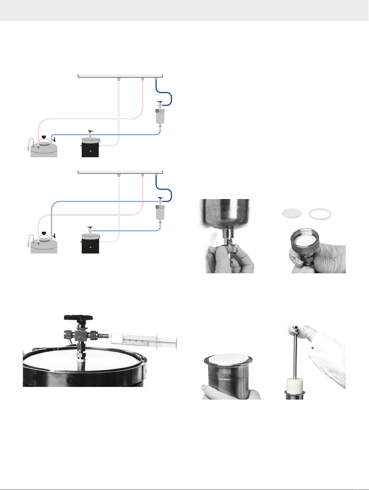
Figure 12
PRR-01
BIOTAGE®FLASH 75/150
CHROMATOGRAPHY
AM-190 MANIFOLD
PRR-02
MV-01
PG-01 PG-02
MV-03 MV-02
N2N2
N2
A B
A
C
Inert gas supply
D
E
.Schematics of a system without the sample injection module (SIM).
Figure 13
PRR-01
BIOTAGE®FLASH 75/150
CHROMATOGRAPHY
AM-190 MANIFOLD
PRR-02
MV-01
PG-01 PG-02
MV-03 MV-02
N2N2
N2
A B
A
C
Inert gas supply
B
D
E
PRR-01
BIOTAGE®FLASH 75/150
CHROMATOGRAPHY
AM-190 MANIFOLD
PRR-02
MV-01
PG-01 PG-02
MV-03 MV-02
N2N2
N2
A B
A
C
Inert gas supply
B
D
E
.
Schematics of a system ready-for-use when equilibrating the system and loading liquid sample (left) and when loading solid sample (right).
A = AM-190 manifold, B = sample injection module (SIM), C = solvent reservoir, D = radial compression module, and E = fraction collection vessel.
Yellow tube = pressurized inert gas inlet, green tube = inert gas to the radial compression module, red tube = inert gas to the solvent reservoir,
blue tube = inert gas to the sample injection module, and clear PTFE tubes (light blue in the schematics) = solvent supply, SIM outlet, and fraction collection.

Biotage®Flash 75/150 User Manual | © Biotage 2018
Installation
Ground the System
Warning
»
The system, when operated with non-polar solvents such as
hexane, methylene chloride, etc., can build up a high static
electricity charge, which in certain conditions can be dangerous.
To eliminate any risk of a static discharge, the systems and
ancillary containers must be grounded before use as described
below. Failure to follow these grounding instructions may result
in equipment damage, personal injury, or death.
»
A trained person must verify that the system and ancillary
containers are grounded before each run. Nominal resistance
must be below 5 Ohm between ground and each metal point in
the system.
The pre-wired grounding kit that is supplied with the system
includes a complete wiring harness assembly (see Figure 14)
and a pair of fraction collection assemblies (see Figure 15).
Figure 14.The wiring harness assembly included in the grounding kit.
Figure 15.The fraction collection assembly for the Flash 75 system (left)
and the Flash 150 system (right).
Note: All the alligator clips must be connected to metal
fittings/objects, not to the plastic tubing.
Note: Before installing the grounding kit, ensure that the system
tubing has been installed in accordance with the instructions in
“Attach the Inert Gas Supply and Solvent Lines” on page 10.
1. Connect the first alligator clip (item 1 in Figure 16) to a
grounded point, such as a metal cold water pipe.
Note: To be an acceptable grounding point, the entire run of
pipe must be made of metal. Have a qualified person, such
as an electrician, verify that the point is grounded before
operating the system.
2. Connect the next alligator clip (item 2 in Figure 16) to the
on/off valve on the top of the solvent reservoir, at the point
where the metal tubing connector is located.
3. Connect the next alligator clip (item 3 in Figure 16) to the
three-way valve on the top of the sample injection module,
at the point where the metal tubing connector is located.
4. Connect the next alligator clip (item 4 in Figure 16) to the
bottom of the sample injection module, at the point where
the metal tubing connector is located.
5. Connect the next alligator clip (item 5 in Figure 16) to the
three-way valve on the top of the radial compression module,
at the point where the metal tubing connector is located.
6. Connect the last alligator clip (item 6 in Figure 16) to the
metal fitting on the bottom of the radial compression
module.
7. Connect the fraction collection assembly tube (item 7
in Figure 16) to the fitting on the bottom of the radial
compression module as described in “Fitting with Nut and
Ferrules” on page 10.
Note: The grounding kit contains two fraction collection
assemblies. The one with the smaller nozzle and a tube with
an outer diameter of 1/8" is for Flash 75 and the one with the
larger nozzle and a tube with an outer diameter of 1/4" is for
Flash 150; see Figure 15.
8. Wrap the uninsulated wire (item 8 in Figure 16) that connects
to the last alligator clip (item 6 in Figure 16) around the
fraction collection tube (item 7 in Figure 16) and then
securely tighten the terminal ring on the uninsulated wire
(item 9 in Figure 16) between the two hex nuts on the
fraction collection nozzle (item 10 in Figure 16).
9. Verify that the system is grounded using an electrical
multimeter (DVM). Nominal resistance must be below 5 Ohm
between ground and each metal point in the system.

Installation
Figure 16
PRR-01
BIOTAGE®FLASH 75/150
CHROMATOGRAPHY
AM-190 MANIFOLD
PRR-02MV-01
PG-01 PG-02
MV-03 MV-02
N2N2
N2
A B
.System grounding schematic. Note that all the alligator clips must be connected to metal fittings/objects, not to the plastic tubing.
1
Connect
to earth
ground
2
3
4
5
6
7
10
8
9

Biotage®Flash 75/150 User Manual | © Biotage 2018
How to Use the System
Warning
»
Before operating the system, please read and observe the
safety requirements in the “Safety” section on page 7.
Note: We recommend that you keep a logbook of all the runs
performed on the system (with the date, time, user, used
solvent or solvent mixture, and pressure settings for each run)
to keep track of the pressurized cycles.
Fill the Solvent Reservoir
1. Ensure that the two-way valve on the top of the solvent
reservoir is closed; see Figure 17.
2. Ensure that the inert gas supply is turned off and that the
three valves on the AM-190 manifold are set to their off/vent
positions (see Table 2 on page 3).
3. Take the necessary precautions to avoid exposure to harmful
gases and open the lid by loosening the clamp screw and
then tilting the lid.
4. Ensure that the system is grounded; see “Ground the
System” on page 12.
5. Fill the solvent reservoir with the desired solvent.
Note: If the solvent reservoir is not empty, ensure that you
fill it with the same solvent or solvent mixture.
6. Put the lid back in place by tilting and lowering it into the
mouth of the solvent reservoir. Hand-tighten the clamp to
secure the lid.
Figure 17
ClosedOpen
.The two-way on/off valve on the solvent reservoir open (left)
and closed (right).
Insert a Flash Cartridge
Warning
»
Never run the system without a cartridge, or with the wrong
size of cartridge.
»
Never loosen the V-band clamps when the radial compression
module is under pressure. A red pressure indicator on the radial
compression module sticks out when the pressure is above
20 psi (1.4 bar); see Figure 2 on page 2.
»
Inspect the V-band clamp before and after each use. The clamp
must be replaced when it shows any signs of wear and tear, or
at 500 pressure cycles, whichever comes first. Only use clamps
and screws supplied by Biotage.
»
Confirm that the V-band clamp is tight before compressing the
radial compression
module. Only hand-tighten the clamp to a
maximum torque of 100 lbf-in (11.3 Nm). If the cartridge is
not sealed properly, replace the O-ring and retry, or contact
Biotage 1-Point Support.
1. Ensure that the three-way valve on the radial compression
module and the two-way valve on the top of the solvent
reservoir are closed.
2. Ensure that the inert gas supply is turned off and that the
three valves on the AM-190 manifold are set to their off/vent
positions (see Table 2 on page 3).
3. Remove any outer plastic wrapping from the cartridge.
You may wish to keep label information for your records.
4. Remove the end caps from the cartridge and keep them.
5. Loosen the upper and lower V-band clamps.
6. Remove the top head assembly from the radial compression
module.
7. Lower the cartridge into the radial compression module and
confirm that it is level with the top of the barrel.
Note: If the cartridge does not go all the way into the radial
compression module, loosen the lower V-band clamp until
the cartridge top is level with the top of the barrel.
8. When the cartridge is level with the top of the barrel, ensure
that the O-ring is secure inside the groove in the top lip of the
barrel and that it is not damaged; see Figure 26 on page 19.
Note: If the O-ring shows any signs of wear or damage,
replace it. Two spare O-rings are supplied with the system.
9. Place the top head assembly back in place and hand-tighten
the V-band clamps alternating between the upper and lower
until secure.
Tightening the V-band clamp will engage the knife-edge seal
into the cartridge and engage the O-ring to seal the inert
gas pressure within the barrel. Note that the V-band clamp
should not be over-tightened. Maximum recommended
tightening torque is 100 lbf-in (11.3 Nm).
How to Use the System
How to Use the System
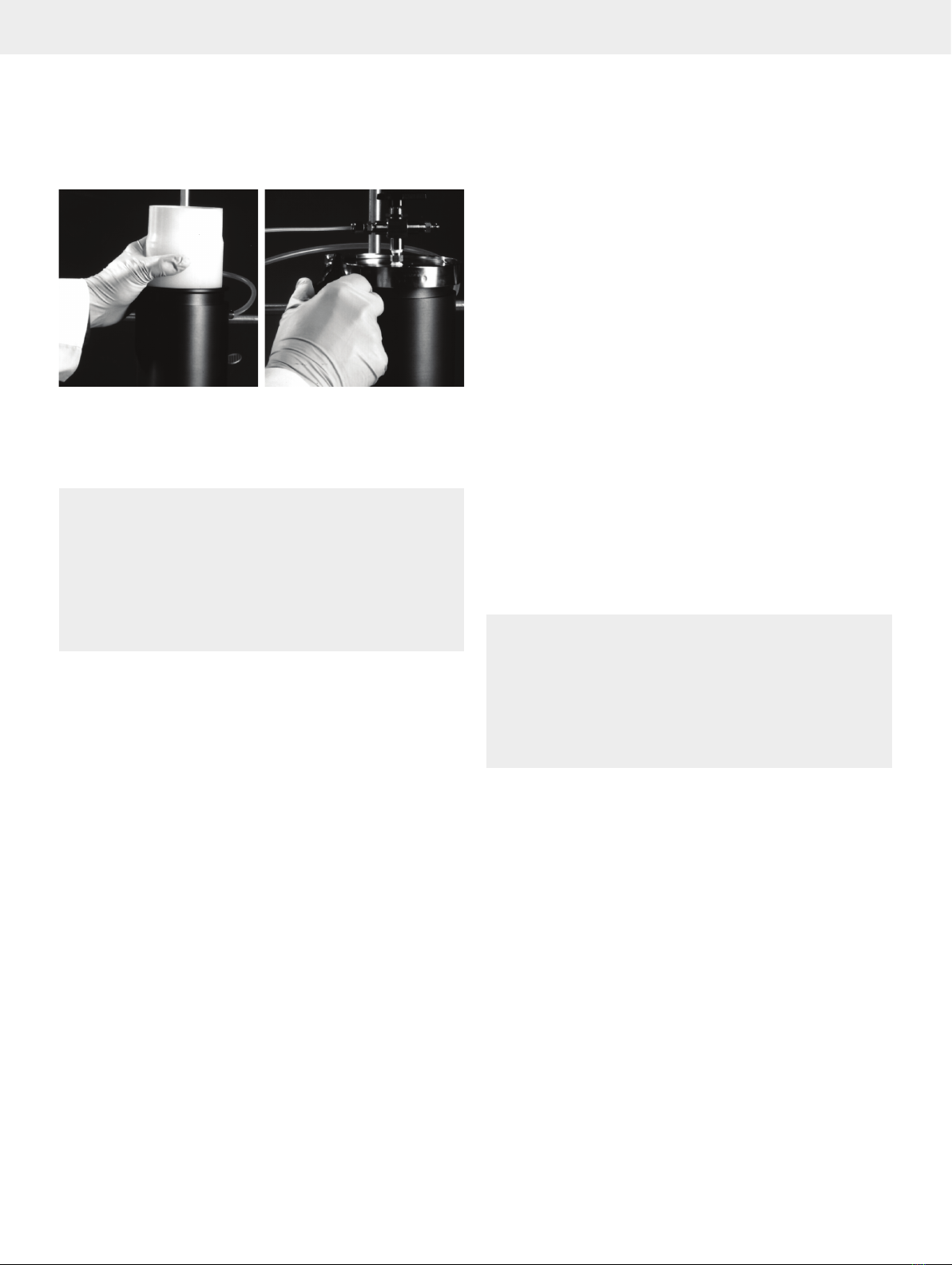
Figure 18.Inserting a flash cartridge into the radial compression module.
Pressurize the Radial Compression
Module and the Solvent Reservoir
Warning
»
The system is operated using pressurized inert gas. Ensure that
all seals are properly mounted and that all clamps are properly
closed before introducing pressurized gas into the system.
»
To avoid injury to yourself or damage to the system, set
the inert gas supply pressure to between 100 and 125 psi
(6.9 to 8.6 bar).
»
Follow all applicable safety procedures when working with
bottled gas.
1. Ensure the system is grounded; see “Ground the System” on
page 12.
2. Ensure that the three-way valve on the radial compression
module and the two-way valve on the solvent reservoir are
closed.
3. Ensure that all the lines are properly connected as described
in “Attach the Inert Gas Supply and Solvent Lines” on
page 10 and that there is solvent in the solvent reservoir.
Note: If using a SIM, the solvent tube must be connected
between the solvent reservoir and the radial compression
module as shown in the left schematic in Figure 13 on
page 11 for you to be able to equilibrate the cartridge.
The solvent tube may contain solvent; please ensure to
take the necessary precautions to avoid spillage when
disconnecting the tube.
4. Turn on the inert gas supply that is connected to the AM-190
manifold (see A in Figure 4 on page 3). Confirm that the
gas pressure is between 100 and 125 psi (6.9 to 8.6 bar).
5. Pressurize the radial compression module by turning the
MV-01 valve on the AM-190 manifold to the on/pressurize
position (see Table 2 on page 3).
6. Set the radial compression pressure to 100 psi (6.9 bar) by
adjusting the PRR-01 regulator on the AM-190 manifold.
7. Confirm that the cartridge is compressed; the red pressure
indicator on the front of the radial compression module
sticks out (see Figure 2 on page 2).
8. Pressurize the solvent reservoir by turning the MV-03 valve
on the AM-190 manifold to the on/pressurize position (see
Table 2 on page 3).
9. Set the equilibration flow rate/solvent pressure by adjusting
the PRR-02 regulator on the AM-190 manifold as follows:
»
Flash 75M: approx. 30 psi (2.1 bar)
»
Flash 75L and Flash 150M: approx. 45 psi (3.1 bar)
»
Flash 150L: approx. 45 to 60 psi (3.1 to 4.1 bar)
Note: These solvent pressure settings are approximate
guidelines. Your particular mobile phase, depending on its
viscosity, may require a higher or lower pressure.
Note: Ensure that the solvent pressure is at least 20 psi
(1.4 bar) lower than the radial compression pressure.
Equilibrate the Cartridge
Warning
»
Always equilibrate the cartridge.
»
Equilibrate the cartridge at a low flow rate to avoid extreme
temperature rise.
»
Only use waste/fraction collection vessels that are grounded or
made of glass.
»
If the system is placed in a walk-in fume hood, a fume extractor
must be used for open waste/fraction collection vessels.
1. Ensure that the fraction collection nozzle is inserted into a
collection vessel that is grounded or made of glass. If the
system is placed in a walk-in fume hood, a fume extractor
must be used for open collection vessels.
2. Turn the three-way valve on the radial compression module
toward the tube connected to the solvent reservoir.
3. Open the two-way valve on the solvent reservoir and allow
solvent to flow through the cartridge.
4. When solvent exits from the fraction collection nozzle, close
the two-way valve on the solvent reservoir and empty the
collection vessel.
Biotage®Flash 75/150 User Manual | © Biotage 2018
How to Use the System
Load Sample and Collect Fractions
A liquid sample or a solid sample that has been pre-adsorbed
on silica can be loaded onto the equilibrated cartridge using
a sample injection module (SIM); see Figure 19 and Figure 20.
Figure 19
PRR-01
BIOTAGE®FLASH 75/150
CHROMATOGRAPHY
AM-190 MANIFOLD
PRR-02
MV-01
PG-01 PG-02
MV-03 MV-02
N2N2
N2
A B
.Liquid sample loading using a sample injection module (SIM).
Figure 20
PRR-01
BIOTAGE®FLASH 75/150
CHROMATOGRAPHY
AM-190 MANIFOLD
PRR-02
MV-01
PG-01 PG-02
MV-03 MV-02
N2N2
N2
A B
.Solid sample loading using a sample injection module (SIM).
Alternatively, if the sample is soluble in a small volume of
solvent, it can be injected with a syringe through a Luer-lock
injection port on the radial compression module; see
Figure 21. The port is fitted by disconnecting the SIM outlet
tube from the radial compression module and replacing it with
the Luer-lock injection port (supplied with Flash 150 systems).
Figure 21.Alternatively, if the sample is soluble in a small volume of
solvent, it can be injected with a syringe through a Luer-lock injection
port on the radial compression module.
Load the Sample into the SIM
1. Ensure that the MV-02 valve on the AM-190 manifold is set
to its off/vent position (see Table 2 on page 3) and the
two-way valve on the solvent reservoir is closed.
2. If loading a solid sample, close the three-way valve on the
radial compression module and disconnect the solvent tube
connected between the solvent reservoir and the radial
compression module from the module and connect it to the
SIM; see Figure 20.
Note: The solvent tube contains solvent; please ensure
to take the necessary precautions to avoid spillage when
disconnecting the tube.
3. Insert a bottom frit into the SIM's frit holder:
a. Push one bottom frit into a sealing ring.
b. Unscrew the lower half of the frit holder and insert the
sealing ring and frit into the lower half; see Figure 22.
Note: Ensure that the plastic frit is at the bottom of the
frit holder.
c. Screw the lower half of the frit holder back in place.
Finger-tight is normally adequate.
Figure 22.Inserting a bottom frit into the lower half of the frit holder.
4. Loosen the clamp on the SIM and remove the top assembly
(clamp, lid with the three-way valve, and sanitary gasket).
5. Insert a top frit of the correct diameter into the SIM and push
it down to the bottom using the frit insertion tool included in
the SIM kit; see Figure 23.
Figure 23.Inserting a frit into the SIM 2000 body using its frit insertion
tool. Note that the insertion tool for SIM 500 and SIM 1000 does not have
a handle.

How to Use the System
6. Pour the liquid sample or the silica with the adsorbed
sample into the SIM. See Table 4 for maximum volumes.
Note: When working with oils, dilute the sample with elution
solvent until it will flow freely down a glass rod.
SIM Max Volume
(mL)
Max Silica Mass
(gram/SIM Unit*)
500 350 175
1000 900 450
2000 1800 900
Table 4.Maximum volume and nominal mass of silica for the SIM modules.
*This is the maximum amount of silica that fits into the SIM; the actual
amount of silica used will depend on the sample being loaded.
7. If loading a solid sample:
a. Tap the silica down using the frit insertion tool.
b. Insert a second top frit into the SIM and push it down
using the frit insertion tool.
Note: The top frit must be installed or the separation
efficiency will be low.
8. Ensure that the gasket grooves of the lid and SIM body are
free from any particulates.
9. Place the top assembly back in place and tighten the clamp.
Ensure that the sanitary gasket is captured in the grooves of
the lid and SIM body; see Figure 24.
Note: Use a sanitary gasket that compatible with the used
solvent; see “Sanitary Gaskets” on page 4.
Note: If the gasket shows any signs of wear or damage,
replace it.
Note: It is sometimes useful to apply a small amount of
solvent to the groove and gasket to ensure a good seal.
10. To load the sample onto the equilibrated cartridge and elute
fractions, see “Load the Sample onto the Cartridge and
Collect Fractions” below.
Figure 24.The sanitary gasket must be captured in the grooves of the lid
and the SIM body.
Load the Sample onto the Cartridge and Collect Fractions
Collect your fractions in flasks that are grounded or made of glass.
The following are guidelines for vessel types by cartridge volume:
»
Flash 75M (400g): 125-mL flasks
»
Flash 75L (800g): 250-mL flasks
»
Flash 150M (2.5 kg): 1-liter flasks
»
Flash 150L (5.0 kg): 2-liter flasks
Since your compound will not elute in less than one column volume
(CV), you may wish to collect the first 0.5, 1, or 3 to 6 liters in
a larger flask or carboy. As you approach the point where your
compound will elute, use the smaller fraction collection vessels
(see the bullet list above) to maximize your yield and purity.
Note: Based on the predicted retention volume (CP) of the first
compound, the initial solvent volume could be collected in one
large flask to minimize glassware usage.
Warning
»
Only use waste/fraction collection vessels that are grounded or
made of glass.
11. If the SIM contains a liquid sample:
a. Ensure that the fraction collection nozzle is inserted into
a collection vessel that are grounded or made of glass.
b. Turn the three-way valve on the radial compression
module toward the tube connected to the SIM
c. Turn the MV-02 valve on the AM-190 manifold to its
on/pressurize position (see Table 2 on page 3) to
drive your sample onto the cartridge.
d. When the sample has been loaded onto the cartridge,
i.e. when the SIM outlet tubing is dry, turn the MV-02
valve on the AM-190 manifold to its off/vent position
(see Table 2 on page 3).
12. Turn the three-way valve on the SIM toward the tube
connected to the solvent reservoir.
13. Ensure that the solvent reservoir is pressurized, i.e. the
MV-03 valve on the AM-190 manifold is turned to its
on/pressurize position (see Table 2 on page 3).
14. Set the solvent flow rate/solvent pressure by adjusting the
PRR-02 regulator on the AM-190 manifold as follows:
»
Flash 75M: approx. 40 psi (2.8 bar)
»
Flash 75L and Flash 150M: approx. 60 psi (4.1 bar)
»
Flash 150L: approx. 60 to 80 psi (4.1 to 5.5 bar)
Note: These solvent pressure settings are approximate
guidelines. Your particular mobile phase, depending on its
viscosity, may require a higher or lower pressure. For flash
cartridges packed with KP-Sil silica, Biotage recommends a
solvent flow rate between 100 and 250 mL/min for Flash 75
and between 400 and 1000 mL/min for Flash 150.
Note: Ensure that the solvent pressure is at least 20 psi
(1.4 bar) lower than the radial compression pressure.

Biotage®Flash 75/150 User Manual | © Biotage 2018
How to Use the System
15. Ensure that the fraction collection nozzle is inserted into a
collection vessel of a suitable size. See the guidelines above.
Note: If using a solid sample, the sample has not yet been
loaded onto the cartridge. It will be loaded when you open
the two way valve on the solvent reservoir in the next step.
16. Open the two-way valve on the solvent reservoir. Solvent
will then flow through the SIM and cartridge (solid sample)
or cartridge (liquid sample) and out of the fraction collection
nozzle.
17. Once your separation is finished, stop the solvent flow by
closing the two-way valve on the solvent reservoir.
18. Turn the MV-03 valve on the AM-190 manifold to its off/vent
position (see Table 2 on page 3).
19. Close the three-way valve on the radial compression module.
Refill the Solvent Reservoir
If you need to refill the solvent reservoir during a run:
1. Close the two-way valve on the solvent reservoir.
2. Depressurize the solvent reservoir by turning the MV-03
valve on the AM-190 manifold to its off/vent position (see
Table 2 on page 3).
3. When the pressure has been released, open the lid by
loosening the clamp screw and then tilting the lid.
4. Ensure that system is grounded; see “Ground the System”
on page 12.
5. Take the necessary precautions to avoid exposure to
harmful gases and then fill the solvent reservoir with the
desired solvent.
Note: If changing solvent, the new solvent must be miscible
with the previous solvent.
6. Put the lid back in place by tilting and lowering it into the
mouth of the solvent reservoir. Hand-tighten the clamp to
secure the lid.
Empty the Solvent Reservoir
Warning
»
Only use waste/fraction collection vessels that are grounded or
made of glass.
If you want to empty the solvent reservoir after the run, this is
preferably done before depressurizing the radial compression
module.
1. Ensure that the three-way valve on the radial compression
module and the two-way valve on the solvent reservoir are
closed.
2. Disconnect the solvent tube from the radial compression
module and insert it into a collection vessel of a suitable size.
3. Turn the MV-03 valve on the AM-190 manifold to its
on/pressurize position (see Table 2 on page 3).
4. Lower the solvent pressure to 15 psi (1 bar).
5. Take the necessary precautions to avoid exposure to
harmful gases.
6. While firmly holding down the solvent tube into the
collection vessel, slowly open the two-way valve on the
solvent reservoir.
Depressurize the Radial Compression
Module and Remove the Used Cartridge
Warning
»
Never loosen the V-band clamps when the radial compression
module is under pressure. A red pressure indicator on the radial
compression module sticks out when the pressure is above
20 psi (1.4 bar); see Figure 2 on page 2.
»
Only use waste/fraction collection vessels that are grounded or
made of glass.
1. If using a Flash 150 system, reduce the solvent pressure to
less than 50 psi (3.5 bar) by adjusting the PRR-02 regulator
before blowing down the radial compression module.
2. Insert the fraction collection nozzle into a collection vessel
that are grounded or made of glass.
3. Turn the three-way valve on the radial compression module
toward the tube connected to the SIM.
4. Turn the three-way valve on the SIM toward the BLUE tubing
that is connected to the AM-190 manifold.
5. Turn the MV-02 valve on the AM-190 manifold to its
on/pressurize position (see Table 2 on page 3)to blow
inert gas through the SIM and cartridge and drive out any
remaining solvent.
6. When the last of the solvent drains out of the radial
compression module, turn the MV-02 and MV-01 valves on
the AM-190 manifold to their off/vent positions (see Table 2
on page 3).
7. When the radial compression module is not under pressure,
i.e. the red pressure indicator on the front of module is not
sticking out (see Figure 2 on page 2), turn off the inert
gas supply to the system and allow any pressure to dissipate
through the system.
8. Loosen the upper V-band clamp and remove the top head
assembly from the radial compression module.
9. Remove the cartridge using the cartridge extraction tool
supplied with the system; see Figure 25.
10. Put the end caps back on the cartridge and dispose of it in a
safe manner.
This manual suits for next models
1
Table of contents
Other Biotage Water Filtration System manuals


