Sea Recovery SRC Aqua Matic 450-1 User manual
Aqua Matic Modular 450-1800
Owner’s Manual
Initial Release - 1 December 2008
Manual PN B651140002 | Revision: 0//1
SRC Aqua Matic 450-1
SRC Aqua Matic 700-1
SRC Aqua Matic 900-1
SRC Aqua Matic 900-2
SRC Aqua Matic 1400-2
SRC Aqua Matic 1800-2
FOR DECEMBER 2008 MODELS


Aqua Matic Modular 450-1800
Owner’s Manual


Aqua Matic Modular 450-1800
Page i
PREFACE
Thank you for your purchase of a Sea Recovery Aqua Matic
Reverse Osmosis Desalination System. This manual contains
instructions for the installation, operation, maintenance,
and repair of the Sea Recovery Desalination System. This
information is provided to ensure extended life and safe
operation of your Sea Recovery system.
Please read this manual thoroughly before installation
or operation, and keep it for future reference. A better
understanding of the system ensures optimum performance
and longer service life.
Sea Recovery’s Reverse Osmosis Desalination Systems are
designed and engineered to function as a complete working
unit. Generally speaking, the performance of each component
within the System is dependent on the component prior to it
and governs the performance of all components after it. Proper
performance of the system is thus dependent upon proper
operation of every single component within the system.
The intent of this manual is to allow the operator to become
familiar with each component within the Sea Recovery system.
By understanding the function, importance, and normal
operation of each component within each subsystem of the
unit, the operator can readily diagnose minor problems, which
if detected early are usually easily corrected. However, if left
unattended, a problem in one component eventually affects the
rest of the system and leads to further repairs.
The manual is divided into sections that address different
subject matter. Each section should be reviewed before
operating the Reverse Osmosis Desalination system.
The major documented cause of failures and problems are
from the use of third party, non Sea Recovery, parts, from
improper installation, and from improper operation:
The use of third party, non Sea Recovery, consumable, spares,
and assemblies will damage the Sea Recovery system and/
or specific components within the system. Do not use parts,
components from any source other than Sea Recovery. Use of
third party, non Sea Recovery, components will void any and
all warranty of the system and/or void the effected component
within the system.
Sea Recovery maintains inventory for immediate shipment and
our Service Dealers throughout the world maintain stock of Sea
Recovery parts. Always insist on Sea Recovery supplied parts
for your system in order to avoid failures, eliminate problems,
and maintain your Sea Recovery Warranty.
Follow the Installation and Operation Instructions in this manual.
From time to time, Sea Recovery may make programming
changes to the Control Logic.
Other physical production changes may also be made from
time to time and are tracked by Sea Recovery through the
System Serial Number.
Troubleshooting and repair method results can vary
depending on the information that is displayed at the SYSTEM
INFORMATION screen.
• SERIAL NUMBER helps us to determine the latest
physical version and configuration of your system
which is necessary to ensure that we provide you with
the correct information or parts.
• TYPE tells us the production capacity of your system
which gives us a bench mark in diagnosing product
water flow and pressure concerns.
• TIME RUNNING assists us in diagnosing abnormalities
that can occur at given operational time intervals such
as required pump maintenance, or R.O. membrane
element condition.
• VERSION allows us to determine the specific sequential
operation of the system based on the version of the
programmed control logic.
When requesting assistance from Sea Recovery
or Sea Recovery’s service dealers, always:
PROVIDE ALL INFORMATION DISPLAYED
AT THE SYSTEM INFORMATION SCREEN.

Aqua Matic Modular 450-1800
Page ii
COPYRIGHT NOTIFICATION
Copyright 2008-2009®Sea Recovery Corporation. All content
included within this manual, such as text, graphics, logos,
and images, is the property of Sea Recovery Corporation and
protected by U.S. and international copyright laws.
The compilation (meaning the preparation, collection,
arrangement, and assembly) of all content within this manual
is the exclusive property of Sea Recovery Corporation and
protected by U.S. and international copyright laws.
All software used in the design and manufacture of the
Sea Recovery Reverse Osmosis Desalination System is the
property of Sea Recovery Corporation and protected by U.S.
and international copyright laws. All computer and logic
programming used in the design and manufacture of the Sea
Recovery Reverse Osmosis Desalination System the property
of Sea Recovery Corporation and protected by U.S. and
international copyright laws.
The content of this manual and the software, programming,
and graphic designs used in the design and manufacture of
the Sea Recovery Reverse Osmosis Desalination System is for
the purpose of operation, maintaining, and repair of the Sea
Recovery Reverse Osmosis Desalination System. Any other
use, including the reproduction, modification, distribution,
transmission, republication, display, or performance, of the
content within this manual is strictly prohibited.
TERMS AND CONDITIONS
The use of this manual acknowledges acceptance of the terms
and conditions provided herewith and the agreement to comply
with all applicable laws and regulations pertaining to the use of
this manual.
In addition, the use of this manual forms an agreement
that Sea Recovery’s trademarked name or Sea Recovery’s
trademarked logo mark are not to be used in any form or
manner except with Sea Recovery Corporation’s written
permission. Sea Recovery Corporation holds all rights to its
copyrights and trademarks, and to the material contained in
this manual. Any use of such requires the written permission
from Sea Recovery Corporation.
PATENT INFORMATION
Certain aspects of the Sea Recovery Reverse Osmosis
Desalination System are protected by U.S. and International
Patent Laws.
NOTICE OF LIABILITY
The information contained in the manual is distributed on an
“As is” basis, without warranty. While every effort has been
taken in the preparation of this manual, Sea Recovery Corp.
shall not be held liable with respect to any liability, loss, or
damage caused by the instructions contained in this manual.
The information contained in this manual is subject to change
without notice.
TRADEMARKS
The Sea Recovery®logo mark is a U.S. Registered Trademark
and belongs to Sea Recovery Corporation with all rights
reserved. Sea Recovery®is a US Registered trademark of
Sea Recovery Corporation. Aqua Matic™is a trademark of
Sea Recovery Corp.
Aqua Matic Modular 450-1800
Page i
REVISION HISTORY
Rev. Date Affected Pages Description
Ø 1 December 2008 - Initial Release of the 2008 Models.
1 9/23/09 Pg.4-11 & FoldOut Revised Electrical Diagrams
2 11/18/09 - General Re-formatting
3 11/23/09 Pg. 5-2 Multi Media Installation Instructions revision
4 6/23/10 Section 10 Updated Parts / Added NMEA kit
5. 6/23/10 Pg. 2-1, 2-12, & 2-15 AQM modular with new GP pump
6. 6/23/10 Cover New AQM modular with plunger pump
7 5-30-13 Parts View Added HP 75, and Soft Start
8 5-30-13 Electrical & Certificates New Diagrams, New Certificates

Aqua Matic Modular 450-1800
Page iv
TABLE OF CONTENTS
1 INTRODUCTION 1-1
1.1 PURPOSE 1-1
1.2 SAFETY IN GENERAL 1-1
1.3 USING THIS MANUAL 1-1
1.4 TERM USED 1-1
1.5 REFERENCES 1-1
1.6 SAFETY NOTES 1-1
1.7 GRAPHICS 1-1
1.8 GLOSSARY 1-1
2 SYSTEM DESCRIPTION 2-1
2.1 MODELS 2-1
2.2 SPECIFICATIONS 2-1
2.3 COMPLIANCE 2-1
2.4 WARRANTY 2-1
2.5 REGISTRATION 2-1
2.6 PACKING LIST 2-1
2.7 COMPONENT DIMENSIONS 2-1
2.8 DAILY SYSTEM READING 2-1
2.9 CHEMICAL SAFETY 2-1
2.10 TEMPERATURE & PRESSURE EFFECTS 2-1
3 PRE-INSTALLATION NOTES 3-1
3.1 PRECAUTIONS 3-1
3.2 SPECIAL CONSIDERATIONS 3-1
3.3 DISTANCE BETWEEN COMPONENTS 3-2
3.5 COMPONENTS SUPPLIED BY INSTALLER 3-2
3.6 PIPING AND INTERCONNECT DIAGRAMS 3-3
3.7 EXPLANATION OF PRESSURE TRANSDUCERS 3-16
3.8 RO MEMBRANE ELEMENT NOTES 3-17
3.9 COMPONENT DESCRIPTIONS 3-17
4 ELECTRICAL INFORMATION 4-1
4.1 ELECTRICAL REQUIREMENTS AND INFORMATION 4-1
4.2. ELECTRICAL MOTOR SPECIFICATIONS 4-2
4.3. RECOMMENDED CIRCUIT BREAKER 4-2
4.4. RECOMMENDED POWER WIRE SIZE 4-3
4.5. WIRE INSERTION TO TERMINAL STRIPS 4-4
4.6. WIRE SIZE REFERENCES 4-4
4.7. MODULAR MODEL ELECTRICAL INFORMATION 4-6
4.8 MODULAR MODEL WIRING DIAGRAMS 4-11
5 INSTALLATION REQUIREMENTS 5-1
5.1 SYSTEM CONTROL BOX 5-1
5.2 COMPONENTS 5-1

Aqua Matic Modular 450-1800
Page v
5.3 INTERCONNECTING COMPONENTS 5-5
5.4 WATER TANK 5-6
5.5 REMOTE TOUCH SCREEN 5-6
5.6 ELECTRICAL CONNECTIONS 5-6
5.7 LAND FEED WATER PICK-UP 5-6
5.8 UV STERILIZER INSTALLATION 5-8
6 COMMISSIONING 6-1
6.1 CHECK INSTALLATION 6-1
6.2 CHECK R.O. MEMBRANE 6-1
6.3. SETUP CONTROLLER 6-1
6.4 CHECK SYSTEM MANUALLY 6-2
6.5 OPERATION NOTES 6-3
6.6 INITIAL STARTUP 6-4
6.6.1. POSITION SYSTEM VALVES 6-4
6.6.2. APPLY POWER TO THE SYSTEM 6-5
6.6.3. START THE SYSTEM 6-5
6.6.4. LOG SYSTEM READINGS 6-6
6.6.5. SHUTDOWN THE SYSTEM 6-6
6.7 WARNINGS AND CAUTIONS 6-6
7 OPERATION 7-1
7.1 DAILY OPERATION 7-3
7.1.1 POSITION VALVES 7-3
7.1.2 APPLY POWER TO THE SYSTEM 7-3
7.1.3 START THE SYSTEM 7-3
7.1.5. LOG SYSTEM READINGS 7-4
7.1.6. SHUTDOWN THE SYSTEM 7-4
7.2 SYSTEM STORAGE AND CLEANING 7-4
7.3 SHORT-TERM SHUTDOWN 7-8
7.4 LONG TERM SHUTDOWN 7-8
7.5 WINTERIZING PROCEDURE 7-9
7.6 R.O. MEMBRANE CLEANING 7-9
8 MAINTENANCE AND REPAIR 8-1
8.1 WEEKLY QUICK CHECK 8-2
8.2 OPERATOR MAINTENANCE INTERVALS 8-2
8.3 INDIVIDUAL COMPONENT MAINTENANCE AND REPAIR 8-2
8.4 UV STERILIZER MAINTENANCE 8-18
9 TROUBLESHOOTING 9-1
9.1 ALARM AND ERROR SCREENS 9-1
9.2 TROUBLESHOOTING COMPONENTS 9-2
9.3 ELECTRICAL TROUBLESHOOTING 9-18

Aqua Matic Modular 450-1800
Page vi
10 EXPLODED PARTS VIEW 10-1
10.1. WHEN ORDERING 10-1
10.3 AVAILABLE TUBES AND FITTINGS 10-2
10.4 INSTALLATION KIT B001990001 10-5
10.5 MAJOR PARTS 10-6
1. SEA STRAINER ASSY 3/4-B B006080002 10-6
2. BOOSTER PUMP ASSY N200 50/60/1 B016120001 10-7
3. BOOSTER PUMP ASSY N200 50/60/3 B016120002 10-8
4. BOOSTER PUMP HEAD N200 1221515772 10-9
5. MEDIA FILTER ASSY -4 HS/AW/UW B071080002 10-10
6. MULTI MEDIA FILTER PLUMBING ASSY B075000001 10-12
7. PLANKTON FILTER ASSY-SINGLE B008800001 10-13
8. PLANKTON FILTER ASSY-DOUBLE B008800002 10-14
9. PREFILTER DUAL AQM II B108140001 10-16
10. COMMERCIAL PREFILTER ASSY 32.5 SQ FT SRC AQM B109120001 10-18
11. OIL / WATER SEPARATOR ASSY SRC 32.5 SQ FT B111120001 10-19
12. HP PUMP MOTOR ASSY, 1 PHASE B156150001 (Optional) 10-20
13. HP PUMP MOTOR ASSY 3 PHASE B156150002 (Optional) 10-21
14. HP PUMP/MOTOR ASSY PGR 110/220/1 - B156930003 (Standard) 10-22
15. HP PUMP/MOTOR PLGR 110/220/60/1 - B156930006 (Standard) 10-23
16. HP PUMP/MOTOR PLGR 220/60/3 - B156150007 (Standard) 10-24
17. HP PUMP ASSY-12180513CO (Standard) 10-26
18. HP HOSE ASSEMBLY 10-28
19. MEMBRANE RACK 450-1 - B198000032 10-29
20. MEMBRANE RACK 700-1 - B198000033 10-30
21. MEMBRANE RACK 900-1 - B198000034 10-31
22. MEMBRANE RACK 900-2 - B198000035 10-32
23. MEMBRANE RACK 1400-2 - B198000036 10-33
24. MEMBRANE RACK 1800-2 - B198000037 10-34
25. CONTROLLER BOX A15M 10-36
26. CONTROLLER CHASSIS 1 PH B619940001 10-37
27. CONTROLLER CHASSIS 3 PH B619940002 10-38
28. BACK PRESSURE REGULATOR ASSY B476160003 10-39
29. LP BACK PRESSURE PLATE ASSY B515150002 10-40
30. LP TRANSDUCER ASSY B147130002 10-41
31. PH NEUTRALIZER / CHARCOAL DUAL AQMC II / MOD B114140001 10-42
32. CLEAN AND RINSE KIT AQM B591120001 10-43
33. FRESH WATER FLUSH (.50 INCH) B598000008 10-44
34. UV STERILIZER 12VDC 2GPM B5262000CV 10-46
35. SOFT START ASSY B596800006 10-47
36. REMOTE KIT DISPLAY 80FT STD AQMII B610140008 10-48
37. NMEA 2000 ENABLED B610140004 10-49
11 FOLDOUT 11-1

Introduction
Aqua Matic Modular 450-1800
Section 1 - INTRODUCTION

Introduction

Aqua Matic Modular 450-1800
Page 1-1
Introduction
1.6 SAFETY NOTES
Safety issues that require users attention are highlight
through out this manual as follows.
WARNING: A Warning note provides
critical information users must comply
within order to prevent the possibility of
injuries and/or death.
CAUTION: A Caution note provides
important information users must know
to prevent the possibility of damaging the
device or equipment.
NOTE: A Note provides additional
information users should know to properly
and safely operate the equipment.
1.7 GRAPHICS
Graphics used are for reference and illustration
purposes only, and may not represent the actual part or
arrangement of parts in a customized system.
1.8 GLOSSARY
Following terms are helpful in becoming familiar with the
Sea Recovery Reverse Osmosis System.
BOUNDARY LAYER / CONCENTRATION POLARIZATION
When water permeates through the membrane, nearly
all the salt is left behind in the brine channel. In any
dynamic hydraulic system, the fluid adjacent to the wall
of the vessel is moving relatively slow. Even though the
main body of the stream is turbulent, a thin film adjacent
to the wall (membrane) is laminar. This thin film is called
the boundary layer.
At the boundary layer the salts are saturated and can
readily adhere to and pack into the R.O. membrane
element surface if the Feed Water Flow is insufficient.
For this reason it is important to maintain sufficient Feed
Water flow, to prevent Concentration Polarization, through
the R.O. membrane element.
BRINE VELOCITY
The brine flow over the membrane surface is very
important to both product water quality and quantity. At
low flows, concentration polarization occurs, causing the
water quality to decline.
1 INTRODUCTION
1.1 PURPOSE
This manual is intended for Sea Recovery’s system
technicians, technical support, and training personnel.
This manual contains technical information & instructions
for the installation, operation, maintenance, and
troubleshooting of the Sea Recovery Desalination System.
1.2 SAFETY IN GENERAL
Anyone responsible for the installation, operation,
and maintenance of the Sea Recovery Desalination
System must read this manual thoroughly and
comply with the instructions, guidelines, and safety
requirements at all times.
1.3 USING THIS MANUAL
Reading this manual in its entirety will help users to
become familiar with each component within the system.
By understanding the function, importance, and normal
operation of each component, users can readily operate
and diagnose problems.
Aside from this section, this manual is divided into ten
majors sections.
•Section 2: System Description
•Section 3: Pre-installation Notes
•Section 4: Electrical Information
•Section 5: Installation Requirements
•Section 6: Commissioning
•Section 7: Operation
•Section 8: Maintenance & Repair
•Section 9: Troubleshooting
•Section 10: Exploded Parts View
•Section 11: Foldouts
Each section should be reviewed in the order provided
before performing any system operations.
1.4 TERM USED
The term System refers to Aqua Matic System in general
and will be used throughout this manual.
1.5 REFERENCES
All references in this manual refers to other sections
within this manual unless specifically defined.

Aqua Matic Modular 450-1800
Page 1-2
Introduction
SPIRAL-WOUND MEMBRANE
The spiral-wound membrane consists of multiple
membrane envelopes each formed by enclosing a
channelized product water carrying material between two
large flat membrane sheets. The membrane envelope
is sealed on three edges with a special adhesive and
attached with the adhesive to a small diameter pipe.
A polypropylene screen is used to form the feed water
channel between the membrane envelopes. A wrap
is applied to the membrane element to maintain the
cylindrical configuration. The center tube is also the
permeate (product water) collecting channel. Several
elements may be connected in series within a single or
multiple pressure vessels).
WATER TEMPERATURE EFFECT
The product water flow through the membrane is
significantly affected by the water temperature. At any
given pressure this flow increases with increasing water
temperature and is reduced at lower temperatures.
The System over comes this factor by self adjusting
the operating pressure to maintain a precise amount of
Product Water Flow.
In addition to inferior product water quality, low brine
flows can increase the precipitation of sparingly soluble
salts which will foul the R.O. membrane element surface
(concentration polarization). If this occurs, the product
water flux (production) will decline.
The Feed Pump integrated design provide a relatively
smooth and continual flow of Feed Water across and
through the R.O. membrane element.
COMPACTION
Some densification of the membrane structure may
take place while operating at elevated pressures, above
1000 PSI. The change is known as compaction and is
accompanied by a reduction in the water permeation rate.
When the R.O. membrane element is subjected to
elevated pressures beyond 1000 PSI the Product Water
Channel becomes squeezed which results in restriction
and in turn product water recovery reduction.
OSMOTIC PRESSURE
The transfer of the water from one side of the membrane
to the other will continue until the head (pressure) is
great enough to prevent any net transfer of the solvent
(water) to the more concentrated (feed water) solution.
At equilibrium, the quantity of water passing in either
direction is equal, and the head pressure is then defined
as the ”Osmotic Pressure” of the solution having that
particular concentration of dissolved solids.
PRESSURE
The operating pressure has a direct affect on product
water quality and quantity. Both factors will increase
as the system pressure increases (higher quantity and
higher quality within design limits).
The system must be operated at the lowest pressure
required to achieve the designed product water flow
rate. This parameter also minimizes compaction, which
proceeds at a faster rate at higher pressures as well as
at higher temperatures.
The System self adjusts its operating pressure to maintain
a precise amount of Product Water Flow. However in
so doing, at low temperatures and or high salinity feed
water conditions the system will operate at higher than
normal pressure in maintaining the specified amount of
product water flow. This is normal, to be expected, and is
due to the design characteristics of the system.

Description
Aqua Matic Modular 450-1800
Section 2 - SYSTEM DESCRIPTION

Description
Aqua Matic Modular 450-1800
Page 2-1
Description
2 SYSTEM DESCRIPTION
Since 1981, Sea Recovery Corporation has been
producing water desalination systems for various
applications to customers all around the world.
Since then Sea Recovery has become one of the top
leaders in advanced water desalination systems for
leisure marine applications.
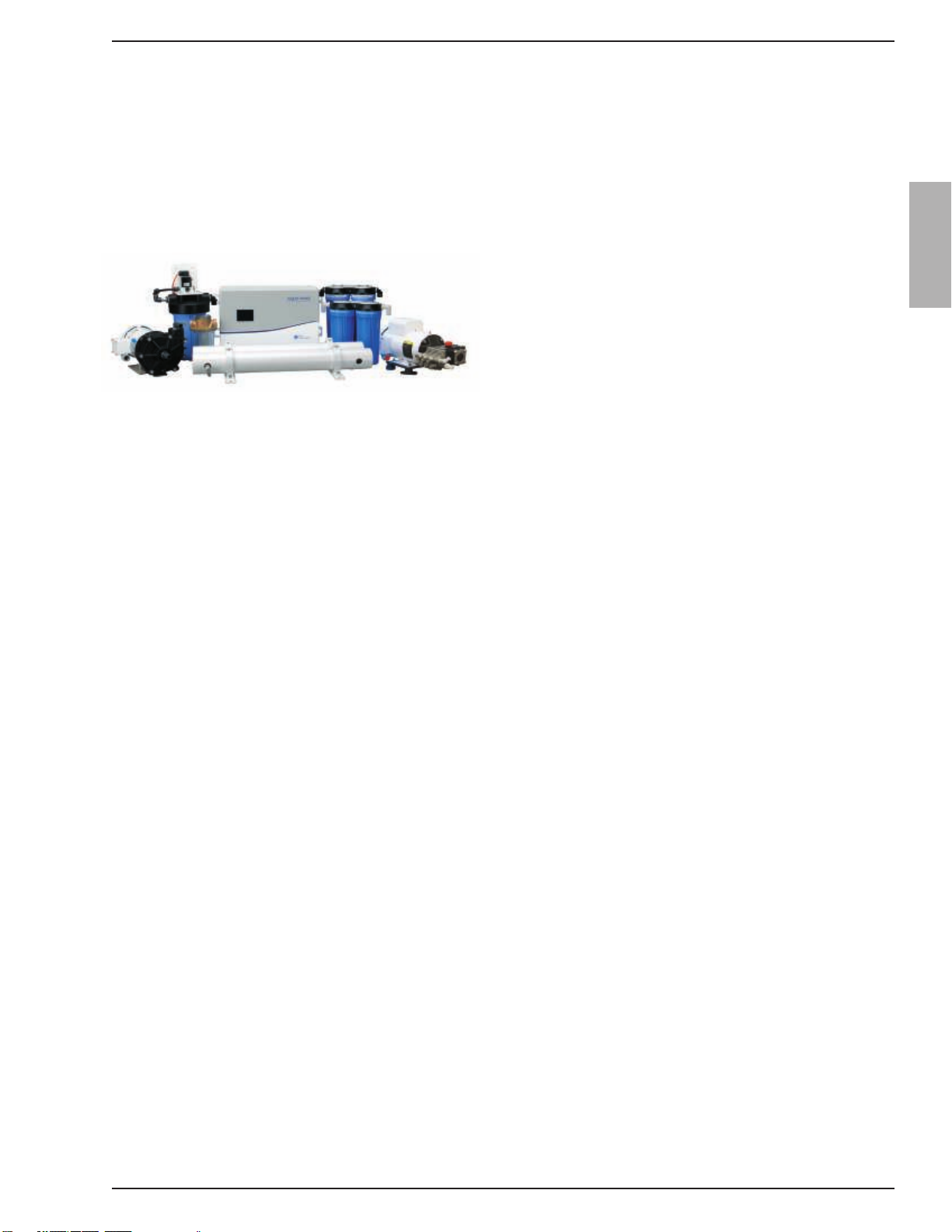
2.1 MODELS
Aqua Matic Modular series are available in six models.
SRC Aqua Matic 450-1• SRC Aqua Matic 700-1• SRC Aqua Matic 900-1• SRC Aqua Matic 900-2• SRC Aqua Matic 1400-2• SRC Aqua Matic 1800-2• 2.2 SPECIFICATIONS
Refer to Page 2-2 for System Specification details.
2.3 COMPLIANCE
Sea Recovery’s Reverse Osmosis Desalination
Systems are Type Accepted by the American Bureau
of Shipping, ABS.
Sea Recovery’s Reverse Osmosis Desalination Systems
comply with FCC § 15.105
Sea Recovery’s Reverse Osmosis Desalination Systems
have been independently tested and determined to be in
compliance with European CE (Conformité Européne).
Refer to Page 2-5 for compliance certificates.
2.4 WARRANTY
Sea Recovery guarantees its product, components, and
replacement parts and recommends customers to use
only Sea Recovery parts. The majority of RO system
problems derive from premature failure of unauthorized
third party replacement parts.
Using unauthorized third party components will lead to
higher operating costs and maintenance costs and labor.
Most importantly, using unauthorized parts will void
Sea Recovery Warranty.
Refer to Page 2-11 for Limited Warranty.
2.5 REGISTRATION
Sea Recovery recommends all customers to register
their System immediately after delivery to ensure and
guarantee product technical support and warranty.
2.6 PACKING LIST
For visual packing list and optional accessories refer
to Page 2-13.
2.7 COMPONENT DIMENSIONS
Refer to Page 2-15 for system and component dimensions.
2.8 DAILY SYSTEM READING
Refer to Page 2-17 for daily system reading log sheet.
2.9 CHEMICAL SAFETY
Refer to Page 2-18 for chemical safety and first aid
recommendations.
2.10 TEMPERATURE & PRESSURE EFFECTS
Refer to Page 2-20 for temperature and pressure effects
on RO membrane performance.

Aqua Matic Modular 450-1800
Page 2-2
Description
SYSTEM SPECIFICATIONS
PERFORMANCE:
PRODUCT WATER PRODUCED PER HOUR AND PER DAY OF OPERATION:
( +-15% at 850 psig / 56 BAR, 77°F / 25°C & 35,000 PPM TDS Feed Water Salinity )
Model Number per 1 hour of operation: per 24 hours of operation:
U.S. Gallons / Liters U.S. Gallons / Liters
SRC Aqua Matic 450-1 19 71 450 1703
SRC Aqua Matic 700-1 29 110 700 2650
SRC Aqua Matic 900-1 38 142 900 3407
SRC Aqua Matic 900-2 38 142 900 3407
SRC Aqua Matic 1400-2 58 221 1400 5300
SRC Aqua Matic 1800-2 75 284 1800 6814
SALT REJECTION (CHLORIDE ION): 99.4%
PRODUCT WATER TEMPERATURE: Ambient to feed water temperature
SPECIFICATIONS:
SALINITY MONITORING: Automatic computer controlled electronic monitoring.
The salinity monitoring components of the system give a continuous readout in micro ohms per cubic centimeter, are
temperature compensated and of a fail-safe design.
SALINITY RANGE OF FEED WATER:
Seawater up to 50,000 PPM TDS (NaCl) (typical seawater salinity is 35,000 PPM)
TEMPERATURE RANGE: Max. 122°F / 50°C, Min. 33°F / .5°C
SYSTEM FEED WATER:
Alternating Current 50 Hz Alternating Current 60 Hz
Feed Water Flow Per Hour: 225 U.S. Gallons / 852 Liters 270 U.S. Gallons / 1,022 Liters
REVERSE OSMOSIS MEMBRANE:
TYPE: Specifically selected High Rejection / High Yield aromatic tri-polyamide, thin film composite, spiral wound,
single pass reverse osmosis membrane element.
CHLORINE TOLERANCE: 0.1 PPM.
pH RANGE: 3-11 (typical seawater pH is 8)
SYSTEM PRESSURE:
FEED WATER: Minimum 6 psi / .42 Kg/cm2. / 41.4 kPa Maximum 40 psi / 2.8 Kg/cm2 / 275.8 kPa
OPERATION: Seawater @ 35,000 PPM & 77º F / 25º C: Nominal 800 psi / / 56.25 Kg/cm2 / 5516 kPa
Aqua Matic Modular 450-1800
Page 2-3
Description
EXTERNAL INSTALLATION WATER CONNECTIONS:
Pipe sizes to be supplied by the installer for connection of the Sea Recovery supplied components
Aqua Matic
Feed Inlet: 3/4 in. (19 mm) MNPT Male National Pipe Thread U.S.
Standard
Brine Discharge 3/4 in. (19 mm) MNPT Male National Pipe Thread U.S.
Standard
Product 1/2 in. (12.7 mm) FNPT Female National Pipe Thread U.S.
Standard
WEIGHT:
MODEL Modular Style
Aqua Matic 450-1 149 lbs / 68 kg
Aqua Matic 700-1 152 lbs / 69 kg
Aqua Matic 900-1 154 lbs / 70 kg
Aqua Matic 900-2 161 lbs / 73 kg
Aqua Matic 1400-2 167 lbs / 76 kg
Aqua Matic 1800-2 172 lbs / 78 kg
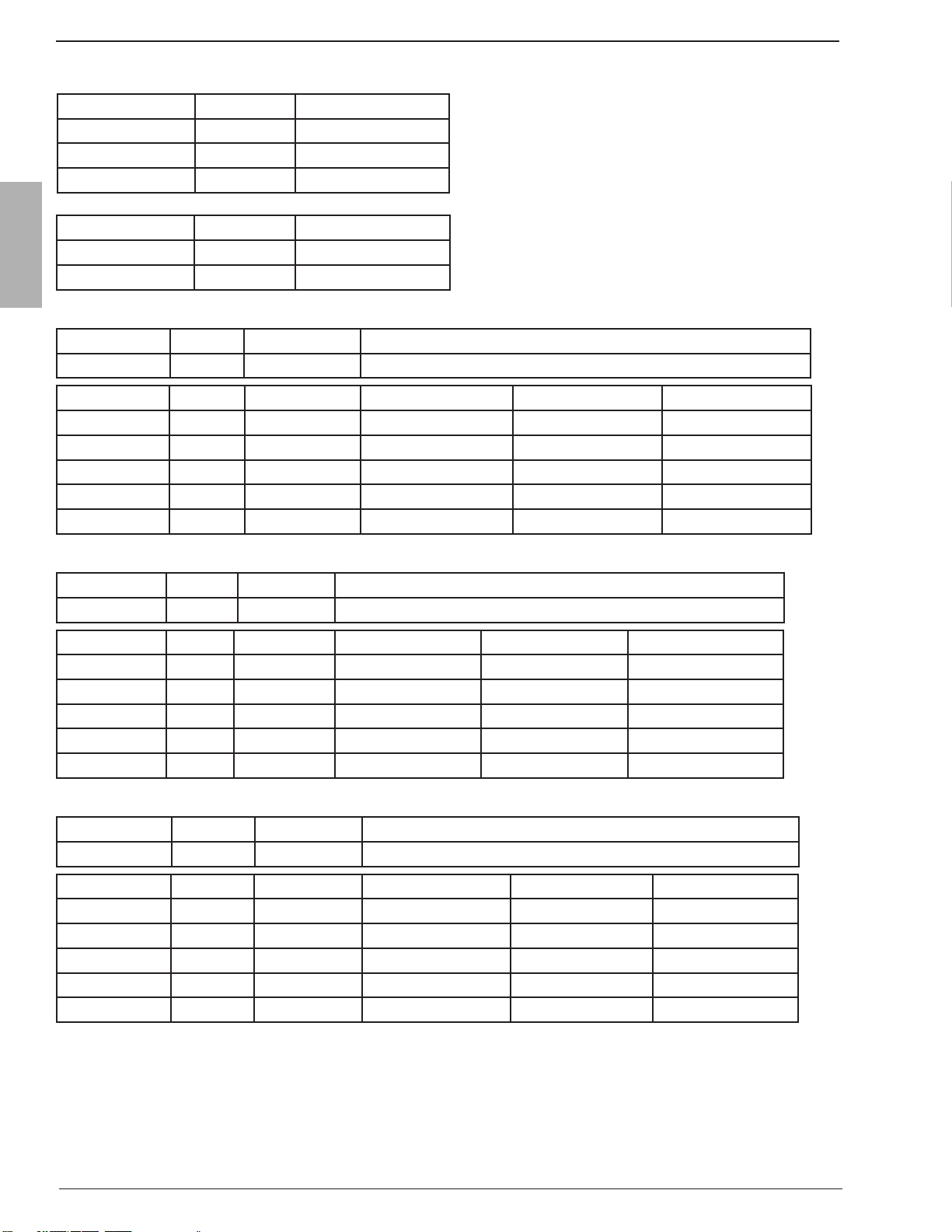
ELECTRICAL MOTOR SPECIFICATIONS:
(H.P. = Horse Power; RPM = Revolutions Per Minute; FLA = Full Load Amperes; LRA = Locked Rotor Amperes @ Start Up)
ALTERNATING CURRENT SYSTEMS:
Single Phase Alternating Current:
High Pressure Pump Motor Booster Pump Motor
VAC Hz H.P RPM FLA LRA H.P RPM FLA LRA
110 50 3 2850 23 89 .5 2850 7.4 20
220 50 3 2850 11.5 44 .5 2850 3.7 10
115 60 3 3450 25.4 86 .5 3450 9.4 20
230 60 3 3450 12.7 43 .5 3450 4.7 10
Three Phase Alternating Current:
High Pressure Pump Motor Booster Pump Motor
VAC Hz H.P RPM FLA LRA H.P RPM FLA LRA
220 50 2.5 2850 7.9 24.9 .5 2850 2.5 8.2
380 50 2.5 2850 4.6 14.4 .5 2850 1.5 4.7
230 60 3 3450 7.6 23.8 .5 3450 2.4 7.9
460 60 3 3450 3.8 11.9 .5 3450 1.2 3.9
Aqua Matic Modular 450-1800
Page 2-4
Description
RECOMMENDED CIRCUIT BREAKER SUPPLYING POWER TO SYSTEM AMPERAGE RATING:
Operating Recommended
AC Voltage Phase Circuit Breaker
110 - 115 VAC Single 50 Ampere
220 - 230 VAC Single 25 Ampere
220 VAC Three 15 Ampere
380 VAC Three 10 Ampere
460 VAC Three 10 Ampere
RECOMMENDED POWER WIRE SIZE TO AQUA MATIC SYSTEM:
Operating Phase Maximum Recommended Minimum Wire Size for Length of run
Voltage Load
10 Ft / 3 meter 25 Ft / 8 meter 50 Ft / 15 meter
110-115 VAC Single 34.8 Ampere 10 AWG / 6 mm2 8 AWG / 10 mm2 8 AWG / 10 mm2
220-230 VAC Single 17.4 Ampere 12 AWG / 4 mm2 12 AWG / 4 mm2 12 AWG / 4 mm2
220-230 VAC Three 10.4 Ampere 14 AWG / 2.5 mm2 14 AWG / 2.5 mm2 14 AWG / 2.5 mm2
380 VAC Three 6.1 Ampere 14 AWG / 2.5 mm2 14 AWG / 2.5 mm2 14 AWG / 2.5 mm2
460 VAC Three 5 Ampere 14 AWG / 2.5 mm2 14 AWG / 2.5 mm2 14 AWG / 2.5 mm2
RECOMMENDED POWER WIRE SIZE TO AQUA MATIC BOOSTER PUMP:
Operating Phase Maximum Recommended Minimum Wire Size for Length of run
Voltage Load
10 Ft / 3 meter 25 Ft / 8 meter 50 Ft / 15 meter
110-115 VAC Single 9.4 Ampere 14 AWG / 2.5 mm2 14 AWG / 2.5 mm2 14 AWG / 2.5 mm2
220-230 VAC Single 4.7 Ampere 14 AWG / 2.5 mm2 14 AWG / 2.5 mm2 14 AWG / 2.5 mm2
220-230 VAC Three 2.5 Ampere 16 AWG / 1.5 mm2 16 AWG / 1.5 mm2 16 AWG / 1.5 mm2
380 VAC Three 1.5 Ampere 16 AWG / 1.5 mm2 16 AWG / 1.5 mm2 16 AWG / 1.5 mm2
460 VAC Three 1.2 Ampere 16 AWG / 1.5 mm2 16 AWG / 1.5 mm2 16 AWG / 1.5 mm2
RECOMMENDED POWER WIRE SIZE TO AQUA MATIC HIGH PRESSURE PUMP:
Operating Phase Maximum Recommended Minimum Wire Size for Length of run
Voltage Load
10 Ft / 3 meter 25 Ft / 8 meter 50 Ft / 15 meter
110-115 VAC Single 25.5 Ampere 12 AWG / 4 mm2 10 AWG / 6 mm2 10 AWG / 6 mm2
220-230 VAC Single 12.7 Ampere 14 AWG / 2.5 mm2 12 AWG / 4 mm2 12 AWG / 4 mm2
220-230 VAC Three 7.9 Ampere 14 AWG / 2.5 mm2 14 AWG / 2.5 mm2 14 AWG / 2.5 mm2
380 VAC Three 4.6 Ampere 14 AWG / 2.5 mm2 14 AWG / 2.5 mm2 14 AWG / 2.5 mm2
460 VAC Three 3.8 Ampere 14 AWG / 2.5 mm2 14 AWG / 2.5 mm2 14 AWG / 2.5 mm2
Other manuals for SRC Aqua Matic 450-1
1
This manual suits for next models
5
Table of contents
Other Sea Recovery Water Filtration System manuals


Popular Water Filtration System manuals by other brands


Eltroplan
Eltroplan Revcon RHF Series operating instructions

Tetra
Tetra Whisper 10-30 manual

Duo-Therm
Duo-Therm GENESIS 3308120.XXX Installation and operating instructions

VGE
VGE XCLEAR user manual

Enpress
Enpress CTA0840BBBKP5-04C00 Installation & operation manual

BestWater
BestWater Jungbrunnen 66-00 Ultimate user manual


