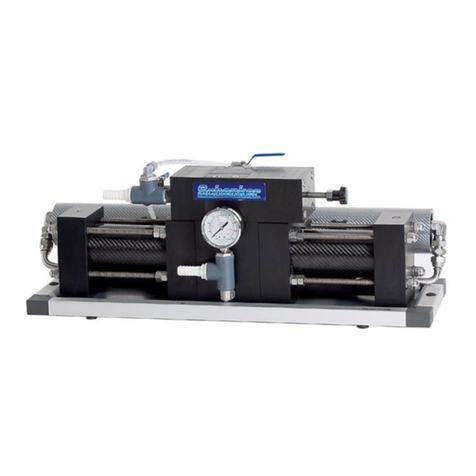
Depuragua RO-50G-A01 User manual

MANUAL/NOTICE DÌNSTALLATION/MANUALE DI INSTALLAZIONE (MODELS RO A01 &E01)
1
Domestic Reverse Osmosis system
INSTALATION AND MAINTENACE MANUAL
Unidad doméstica de Osmosis Inversa
MANUAL DE INSTALACION Y MANTENIMIENTO
Unité d’osmose inverse domestique
NOTICE D’INSTALLATION ET MAINTENANCE
Sistema domestico ad Osmosi inversa
MANUALE DI INSTALLAZIONE E MANUTENCIONE
RO-50/75/100G-A01 RO-50/75/100G-E01

MANUAL/NOTICE DÌNSTALLATION/MANUALE DI INSTALLAZIONE (MODELS RO A01 &E01)
2
Content
1. REVERSE OSMOSIS SYSTEM AND COMPONENTS
2. INTRODUCTION
3. WATER PRODUCTION TECHNOLOGY PROCESS
4. NAME OF COMPONENTS
5. TECHNICAL SPECIFICATIONS
6 INSTALLATION INSTRUCTIONS
7. INITIATION OF THE SYSTEM
8. MAINTENANCE
9 NOTES
10 TROUBLESHOOTING GUIDE
SCHEMES
Please read instructions before installing your RO system. We are convinced that
this device will meet your needs due to its high performance in the production of clean
safe water. If you have any questions or problems contact your
dealer
www.depuragua.com

MANUAL/NOTICE DÌNSTALLATION/MANUALE DI INSTALLAZIONE (MODELS RO A01 &E01)
3
1. REVERSE OSMOSIS SYSTEM AND COMPONENTS
1. Reverse osmosis system
2. Certified food grade tubing
3. Accessories: Water supply valve, link T, faucet and drain
4. Installation manual and maintenance
2. INTRODUCTION
This reverse osmosis unit uses advanced technology to provide water in adequate
conditions of taste smell and security. The heart of the unit lies in the membrane of
reverse osmosis with a precision of 0.0001 Micron, which completely eliminates
bacteria, heavy metals, salt, other harmful minerals, as well as other substances in
solution.
Stages of filtering:
pre-filter PP10: Removes rust, sand, clay and floating substances, generates results
more effective in the carbon filter.
Stage 2: pre-filter GAC10 activated carbon to remove some chemicals organic,
pesticides, floating substances, residual chlorine, bad taste, odors or colors as well as
particles of heavy metals.
Stage 3: pre-filter CTO10 to remove the rust, sand, clay and floating substances.
Stage 4: membrane osmosis -to remove bacteria, heavy metals, salt, mineral
substance and other products harmful in solution as well as chemicals in tap water.
Stage 5: Post carbon filter T33 -to adjust the water's pH value, remove the unpleasant
taste, odors or colors, and make the water taste better.
Stage 6th (optional): UV sterilizer. Uses ultraviolet germicidal quickly and reliably
removes bacteria, viruses and other organisms present in the water.
Magnetization ilter, suitable in areas of hard water.

MANUAL/NOTICE DÌNSTALLATION/MANUALE DI INSTALLAZIONE (MODELS RO A01 &E01)
4
3. TECHNOLOGICAL PROCESS OF WATER PRODUCTION
1 Inlet valve
2.T link
3 PP10 Spun fiber
4 GAC10 carbon filter
granular
5 CTO10 Block carbon
filter
6 Low pressure Switch
(A01)
7. (optional) auto
shut-off valve
8 Pump pressure (A01)
9 Membrane housing
10 Osmosis membrane
11 Check valve
12 Drain restrictor
13 By pass valve
14 Ball valve
15 Pressure tank
(Approximately 8 litres)
16 High pressure
Switch (A01)
17 T33 Carbon filter
18 Faucet
19. (optional) Solenoid valve
5. TECHNICAL SPECIFICATIONS
Voltage and frequency of input: ~ 220V / 50 Hz
Working voltage: 24 V
Pump consumption: 25W ~ 36W
Pure water output capacity: 200 litres/day approximately
Pressure tank: 12 litres (approx)
Inlet water temperature: 5° C ~ 45° C
Input water TDS: ﹤1200ppm
Chlorine: ﹤0.2ppm
Water recovery rate: 92% ~ 99%
(Depends on the quality of the inlet water)
Pressure of inlet water: 0.1MPa ~ 0.4mpa
Water inlet validity: standard municipal water
6 INSTALLATION INSTRUCTIONS
1. Preparations Check accessories (image 2)
2. Connection diagram (image 3)
3. Installation

MANUAL/NOTICE DÌNSTALLATION/MANUALE DI INSTALLAZIONE (MODELS RO A01 &E01)
5
The system was designed to fit under a sink, however, due to space limitations or other
reasons the flexible design of the system allows other places. In determining the location
remember the importance of having a line of cold water, drain, and provide easy access to the
replacement of the filters.All components and piping should be located in an area that is not
exposed to freezing temperatures. Do not expose the unit or tube to direct sunlight.
3.1. Faucet (image 8)
Faucet should be placed near a sink where the water is normally obtained providing ease of
use (filling jugs, water bottles and glasses), and an open area under the faucet under the sink for
the fixing of the product and the drain pipe.
Required a free space of about 5-6 cm diameter flat surface above and below the place of
installation. The thickness of the mounting surface should not exceed 5 / 4 "." The water supply to
the unit must be cold water, hot water would undermine the system.
3.2. Water supply connection (Image 9)
The water supply valve must be located as near can unity. Use only cold water inlet. (Soft)
soft water is more suitable because it will prolong the life of the Membrane.
3.3. Drain connection (image 4)
Waste should go to drain through an anti-siphon air Chamber. The air space is planned at the
base of the faucet. If poured into a sink of service or column,You must provide an air space of
more than 1 "above the flood rim. "
Do not connect the drain line for the system to drain the washing machine or close the Elimination
of waste, pressure of these units can make the air space it overwhelms. The following are
instructions for downloading into the sink drain.
Place the drain pipe drain clamp above the drain trap. Leave space for the drilling. Tighten
securely.
Use drill. Using port bracket as a guide, drill a hole of 7 / 32 "on the wall of the drain pipe. " Do not
penetrate the opposite side of the pipe.
Look for 1 drain tube / 4 "."
Note: Cutting tube cleanly without irregularities, failure to do so could result in a bad connection
and possible leak.
Caution: The lowest point of the line should be the point of connection with drainage clamp. There
should be no bends in the line since it may cause excessive noise when the rejection water is
flowing to the drain.

MANUAL/NOTICE DÌNSTALLATION/MANUALE DI INSTALLAZIONE (MODELS RO A01 &E01)
6
3.4 Tank installation (image 5)
Cover screw tank with Teflon to avoid leakage.Attach the top tank valve.
Connect the osmosis membrane tube to the tank valve
The key of the tank should remain open to let the system accumulate water
3.5 Reverse osmosis unit.- (image 3)
The unit can be installed on the right or left the area under sink or on furniture. It is recommended
the right side for convenience. The installation in the basement is also an option, at a place near
the sink with water and access to the drain. The mounting location must allow an adequate
tolerance and accessibility to change cartridges. Connect the pipes fitted according to the color
scheme
7. INITIATION OF THE SYSTEM
Once the installation.
0 Make sure the membrane is in the porta membrane (part 9)
1 Open the supply of cold water (part 1)
2 Check the system for leaks.
3 Open the tap (part 18).
4 Plug the equipment to the mains
5 Check that wash (Part 13) key is closed
6 After a few minutes, the water begins to drip of the tap, let it drop for about 10 minutes, and close
the knob (item 18). It will take about 2 hours to fill the tank according to the local water
pressure. (Make sure that the tank (part 14) is open)
DO NOT DRINK WATER PRODUCED IN THE FIRST TANK.
7 When the tank is full (will know it because the pump stops), empty the tank by opening the
osmosis faucet until no more water comes out or very little
6 After complete discharge of water from the first tank, turn off the tap and wait for the tank to fill
again, repeat steps 6 and 7 once more.
8 The third tank is full, you can enjoy purified water.
9 Check that there are no leaks daily during the first week and periodically after the first week
10 You may detect some white turbidity in the water, this is due to air bubbles during the first week,
it is completely safe and normal. They will disappear over time.

MANUAL/NOTICE DÌNSTALLATION/MANUALE DI INSTALLAZIONE (MODELS RO A01 &E01)
7
8. MAINTENANCE
To ensure that the system works at its optimum level, they must perform certain maintenance
routines. Maintenance frequency will depend on the level of use, as well as the quality of the inlet
water
8.1 Membrane Cleaning:
Every 3 or 4 weeks open drain (Part 13) key for 3 minutes to perform a backwash membrane
washing, then you leave the key in closed position
8.2 Filter replacement:
Replace PP10 pre-filter every 3 to 6 months depending on the quality of the raw water and
consumption.
Switch GAC10 prefilter and CTO10 every 6 to 12 months.
Membrane change every 24 to 36 months, in areas of hard water (with high lime) replacement will
be held every 12 months
Post Carbon T33 filter change every 6 to 12 months.
If you do not use the system for a long time (it is vacation, travel, etc.) Please be sure to
disconnect the power supply, cutting the water supply and drain the tank.
8.4 How to change cartridges and membrane.
Prior to the change:
1.0 Unplug the equipment from the electrical outlet (A01)
1.1 Valve water supply (1)
1.2 Close the valve of the tank (14). Open faucet to release pressure
1.3 Carry out disinfection of the equipment at the same time that performs the following steps (see
point 8.5)
Change of pre and post filters
1.4 Unscrew container vessels of the filter (with racket key)
1.5 Changing the filters and thread the vessels with the racket spanner
1.6 Change T33 post-filter.
Change of membrane
1.7 Disconnect the tubing from the porta head membrane
1.8 Unscrew carrier head membrane with the key.

MANUAL/NOTICE DÌNSTALLATION/MANUALE DI INSTALLAZIONE (MODELS RO A01 &E01)
8
1.9 Remove membrane membrane sheath.
1.10 Place the new membrane in the membrane housing
1.11 Reconnect tube carrier head membrane
Following change:
1.12 Plug the equipment from the electrical outlet (A01)
1.13 Open valve water supply (1)
1.14 Open the valve of the tank (14). Open faucet to release pressure
1.15 Let the team produce 1 water tank and reject it (do not drink that water)
1.16 After from finished the change because you can enjoy pure water again.
(See picture 6)
8.5. System disinfection.
Your reverse osmosis system should be disinfected periodically (usually done once a year
coinciding with the change of filters) You have to disinfect 3 elements, vessels, the,
membranes and deposit.
Step 1: Prepare a disinfectant solution
Purchase a disinfectant solution to osmosis or failing to prepare it with tap water and a few
drops of food Sanitizer per liter of water. (not necessary more because if we put too much you can
leave a taste in the water for a few days). For the deposit is not necessary to bleach because the
tap water because it contains chlorine.
Step 2: Disinfection of vessels
1 Open the vessels by unscrewing the lid.
2 Remove filters and throw away them
3 Fill vessels with the solution and leave it for 30 minutes.
4 Empty the vessel and dry them with a clean cloth.
5 Replace the filter and screw tubes vessels.
6 Continue with disinfection of the membrane
Step 3: The porta disinfection membranes
1 Open the porta membranes by unscrewing the lid.
2 Remove the membrane to replace and pull
3 Fill the porta membranes with the solution and leave it for 30 minutes.
4 Empty the porta membranes and dry with a clean cloth.
5 Replace the new membrane and reconnect tubing.
6 Continue with the tank disinfection

MANUAL/NOTICE DÌNSTALLATION/MANUALE DI INSTALLAZIONE (MODELS RO A01 &E01)
9
Step 4: Disinfection of the deposit:
1 Close water inlet system
2 Open the tap up to that empty all the water in the tank.
3 Connect the water inlet directly to the tank
4 Open the entrance until the half of the reservoir is filled.
5 Close the tank (above)
Note: Filters and membranes are consumables. His replacement time depends on the quality of
the raw water and drinking water. Make the changes with the frequency of security, so you can
ensure the functioning normal of the reverse osmosis system and the quality of the pure water
outlet water, therefore, values exposed are a suggestion for your reference.
9 NOTES
1.Do not perform pulls sudden system elements, as they could cause leaks and damage to the
machine.
2.There is a pressure tank air valve, please do not release air from tank.
3. do not use inappropriate voltage (A01)
4. is convenient to disconnect the plug and close the water valve when the device will not be used
for a long period.
5.You should be careful in transport, download and installation of the unit.
6. Disinfection: time should be a complete disinfection of equipment; this is usually done at least
whenever filter or membrane should be replaced.

MANUAL/NOTICE DÌNSTALLATION/MANUALE DI INSTALLAZIONE (MODELS RO A01 &E01)
10
10 TROUBLESHOOTING GUIDE
Problem Cause Solution
No water comes out
The stopcock is closed
Open the stopcock
Insufficient water
output
1.The supply of water is locked
2.Pre-filters lock
3. valve closed or appliance ajar
4. the tank valve is closed
5. improper connection of
drainage or closed restrictor
1.Unlock the entry
2.Replace pre-filtering cartridge
3. Open valve
4. Open valve
5. Clean or replace the drain
restrictor
Pump (A01) 1.Low pressure input
2.Loss of power or power off
3.Damaged adaptor
1.Check the inlet pressure
2.Turn on device
3.Replace or repair the adapter
4.revise connection switches
The pump runs but
produces no water
(A01)
1.Clogged carbon pre-filter
2.The inlet solenoid valve failure 1.Check and replace cartridge
2.Check and replace the solenoid
valve
The system does not
shut down (A01) High pressure switch does not
work Replace or repair the switch
Abnormal operating
noise Pre filter clogged or low inlet
pressure Replace the filter or adjust the inlet
pressure
Not drain water Drain restrictor blocked Replace drain restrictor
The water has a bad
taste or odor Exhausted filters or membrane Carry out disinfection and change
filters or membrane
Tubing leaks 1.Poorly connected tubes
2.Defective tubes
3.O-ring not seated properly
4.Broken o-ring
1 and 2.Tighten and adjust tubes
3.Cut the damaged area of the tube
and replace
3.Remove gasket and insert
4.Replace gasket

MANUAL/NOTICE DÌNSTALLATION/MANUALE DI INSTALLAZIONE (MODELS RO A01 &E01)
11
CONTENIDO
1. EL SISTEMA DE OSMOSIS Y SUS COMPONENTES
2. INTRODUCCION
3. PROCESO TECNOLOGICO DE PRODUCCION DE AGUA
4. NOMBRE DE LOS COMPONENTES
5. ESPECIFICACIONES TÉCNICAS
6. INSTRUCCIONES DE INSTALACIÓN
7. INICIACION DEL SISTEMA
8. MANTENIMIENTO
9. NOTAS
10. GUIA DE RESOLUCION DE PROBLEMAS
ESQUEMAS
Lea las instrucciones antes de proceder a la instalación de su sistema de
Osmosis. Estamos convencidos de que este dispositivo satisfará sus necesidades
debido a su alto rendimiento en la producción de agua limpia y segura Si tiene alguna
duda o problema contacte con su distribuidor
www.depuragua.com
1. EL SISTEMA DE OSMOSIS Y SUS COMPONENTES
1
. Sistema de osmosis inversa
2. Tubería certificada de grado alimentario
3. Accesorios: Válvula de alimentación de agua, enlace T, Grifo y desagüe
4. Manual de instalación y mantenimiento

MANUAL/NOTICE DÌNSTALLATION/MANUALE DI INSTALLAZIONE (MODELS RO A01 &E01)
12
2. INTRODUCCIÓN
Esta unidad de osmosis inversa utiliza una avanzada tecnología para
suministrarle agua en adecuadas condiciones de sabor olor y seguridad. El corazón
de la unidad radica en la membrana de osmosis inversa con una precisión de 0.0001
micrones, la cual elimina totalmente las bacterias, los metales pesados, la sal, otras
sustancias minerales dañinas, así como otras sustancias en disolución.
Fases del filtrado:
Etapa 1: Prefiltro PP10: Elimina la herrumbre, arena, arcilla y sustancias flotantes,
permite generar resultados mas efectivos en el filtro de carbono.
Etapa 2: Prefiltro GAC10 de carbón activado - Para la eliminación de algunos
productos químicos orgánicos, pesticidas, sustancias flotantes, cloro residual, sabor
desagradable, olores o colores, y así como partículas de metales pesados.
Etapa 3: Prefiltro CTO10 - Para quitar el óxido, arena, arcilla y sustancias flotantes.
Etapa 4: Membrana osmosis - Para la eliminación de bacterias, metales pesados, la
sal, sustancia mineral y otros productos dañinos en disolución así como químicos en
el agua corriente.
Etapa 5: Post Filtro de carbono - Para ajustar el valor pH del agua, quitar el sabor
desagradable, olores o colores, y hacer el gusto del agua mejor.
Etapa 6 (Opcional): Filtro mineralizador, lanza sustancias minerales para mejorar la
calidad del agua.
Etapa 7: (Opcional) Esterilizador Ultravioleta - Utiliza la luz ultravioleta germicida de
forma rápida y fiable elimina bacterias, virus y otros microorganismos presentes en el
agua.
Filtro de magnetización, Conveniente en áreas de agua dura.

MANUAL/NOTICE DÌNSTALLATION/MANUALE DI INSTALLAZIONE (MODELS RO A01 &E01)
13
3. PROCESO TECNOLÓGICO DE PRODUCCIÓN DE AGUA
Agua Pura
4. NOMBRE DE LOS COMPONENTES
(Ver imagen 1)
1 Válvula de entrada
2.Enlace en T
3 Pre filtro PP33 4 Pre filtro GAC 33
5 Filtro de carbón
CTO33 6 Switch de baja
presión (A01) 7 Válvula de auto
apagado (opcional) 8 Bomba de presión
(A01)
9 Recipiente
membrana 10 Membrana de
osmosis 11 Válvula de chequeo 12 Restrictor de
Desagüe
13 By pass válvula de
desagüe 14 Válvula de bola 15 Tanque de presión
(8 Litros aprox.) 16 Switch de alta
presión (A01)
17 T33 Post filtro 18 Grifo 19 Válvula solenoide de entrada (opcional)
5. ESPECIFICACIONES TÉCNICAS
Voltaje y Frecuencia de entrada: ~220V / 50HZ
Voltaje de trabajo: 24 V
Consumo bomba: 25W~36W
Capacidad de salida de agua pura: 200 Litros/día aproximadamente
Tanque de presión: 12 Litros (aprox.)
Temperatura del agua de entrada: 5°C ~ 45°C
TDS del agua de entrada: ﹤1200ppm
Cloro: ﹤0.2ppm
Porcentaje de recuperación de agua: 92% ~ 99%
(Depende de la calidad del agua de entrada)
Presión del agua de entrada: 0.1Mpa ~ 0.4Mpa
Entrada de agua validad: Agua estándar municipal
Membrana de Osmosis Post filtro de carbón Grifo
Agua residual Tanque de presión
Agua entrante
PP Pre filtro
Filtro de carbón activado
PP Pre filtro
Bomba de alta presión (A01)

MANUAL/NOTICE DÌNSTALLATION/MANUALE DI INSTALLAZIONE (MODELS RO A01 &E01)
14
6. INSTRUCCIONES DE INSTALACIÓN
1. Preparativos Compruebe accesorios
(imagen 2)
2. Diagrama de conexión (imagen 3)
3. Instalación
El sistema fue diseñado para caber debajo de un fregadero, sin embargo, debido
a limitaciones de espacio u otras razones el diseño flexible del sistema permite otros
lugares. Al determinar la ubicación recordar la importancia de disponer de una línea
de agua fría, un desagüe, y prever el acceso fácil a la sustitución de los filtros. Todos
los componentes y la tubería deben estar ubicados en una zona que no esté
expuesta a temperaturas de congelación. No exponga la unidad o el tubo a la luz
solar directa.
3.1. Grifo (Imagen 8)
El grifo debe colocarse cerca del fregadero donde el agua se obtiene
normalmente, previendo la comodidad de uso (llenado de jarras, botellas de agua y
vasos), y un área abierta debajo de la llave de agua debajo del fregadero para la
fijación del producto y la tubería de drenaje.
Se requiere una superficie plana libre de espacio de unos 5-6 cm de diámetro por
encima y por debajo del lugar de instalación. El espesor de la superficie de montaje
no debe exceder de 5 / 4 ". El suministro de agua a la unidad DEBE ser de AGUA
FRÍA, El agua caliente perjudicaría el sistema.
3.2. Conexión de alimentación de agua (imagen 9)
El agua de alimentación de la válvula debe estar situada lo más cerca posible de
la unidad. Use Solo entrada de agua potable fría. El agua blanda (descalcificada) es
mas adecuada ya que prolongará la vida de la Membrana.
3.3. Conexión del desagüe (imagen 4)
Los residuos deben ir a drenar a través de una cámara de aire anti-sifón. El
espacio de aire está previsto en la base del grifo. Si vierten en un fregadero de
servicio o de columna, debe proporcionar un espacio de aire de más de 1 "por encima
del borde de inundación.
NO conecte la línea de drenaje del sistema para el desagüe de la lavadora o cerca de
la eliminación de basura, la contrapresión de estas unidades puede hacer que el
espacio de aire se desbordase. Las siguientes son instrucciones para la descarga en
el desagüe del fregadero.

MANUAL/NOTICE DÌNSTALLATION/MANUALE DI INSTALLAZIONE (MODELS RO A01 &E01)
15
Coloque la abrazadera de drenaje en la tubería de drenaje por encima de la
trampilla de desagüe. Deje espacio para la perforación. Apriete con seguridad.
Utilice taladro. Usando el puerto abrazadera como guía, perfore un agujero de 7 / 32
"en la pared de la tubería de drenaje. NO penetrar en el lado opuesto de la tubería.
Busque el tubo de desagüe de 1 / 4 ".
NOTA: Corte el tubo limpiamente sin irregularidades, de no hacerlo podría resultar en
una mala conexión y de posibles fugas.
PRECAUCIÓN: El punto más bajo de la línea debería ser el punto de conexión con la
abrazadera de drenaje. No debe haber dobleces en la línea ya que puede causar el
ruido excesivo cuando el rechazo el agua está fluyendo al drenaje.
3.4 Instalación de Tanque (imagen 5)
Cubra con teflón el tornillo del tanque para evitar fugas.
Fije la válvula del tanque arriba del tanque.
Conecte el tubo de la membrana de osmosis a la válvula del tanque
La llave del tanque debe permanecer abierta para que el equipo acumule agua
3.5 Unidad de osmosis. - (imagen 3)
La unidad puede ser instalada en el lado derecho o izquierdo de la zona de debajo del
fregadero o sobre mueble. Se recomienda el lado derecho por comodidad. La
Instalación en el sótano es también una opción, en un lugar cerca del lavadero con
toma de agua y acceso al de drenaje. El lugar de montaje debe permitir una
tolerancia adecuada y la accesibilidad para cambiar los cartuchos. Conecte los tubos
instalados según el esquema de colores
7. INICIACION DEL SISTEMA
Una vez realizada la instalación.
0. Compruebe que la membrana está en el porta membrana (Pieza 9)
1. Abra la llave de suministro de agua fría (Pieza 1)
2. Revise que el sistema no tenga fugas.
3. Abra el grifo (pieza 18).
4. Enchufe el equipo a la corriente
5. Compruebe que la llave de lavado (Pieza 13) está cerrada
6. Después de unos minutos, el agua comienza a gotear por el grifo, déjela gotear

MANUAL/NOTICE DÌNSTALLATION/MANUALE DI INSTALLAZIONE (MODELS RO A01 &E01)
16
durante unos 10 minutos, y cerrar el grifo (pieza 18). Tomará unas 2 horas en llenar el
tanque en función de la presión del agua local. (Asegúrese de que la llave del tanque
(Pieza 14) está abierta
NO BEBER AGUA PRODUCIDA EN EL PRIMER TANQUE.
7. Cuando el tanque este lleno (lo sabrá porque la bomba se detendrá), vacíe el
tanque abriendo el grifo de osmosis hasta que no salga agua o muy poca
6. Tras la descarga completa del agua del primer tanque, cierre el grifo y espere a que
se llene el tanque de nuevo, repita los pasos 6 y 7 una vez más.
8. Después de que el tercer tanque está lleno, Ya puede disfrutar del agua purificada.
9. Verifique que no hay fugas diariamente durante la primera semana y
periódicamente tras la primera semana
10 Puede que durante la primera semana detecte cierta turbidez blanca en el agua,
esto es debido a las burbujas de aire, es completamente normal y seguro.
Desaparecerán con el tiempo.
8. MANTENIMIENTO
Para asegurar que el sistema funcione a su nivel óptimo, se deben de realizar ciertas
rutinas de mantenimiento. La frecuencia de mantenimiento dependerá del nivel de
uso, así como de la calidad del agua de entrada
8.1 Lavado de membrana:
Cada 3 o 4 semanas abra la llave de desagüe (Pieza 13) durante 3 minutos para
realizar un lavado de la membrana a contracorriente, luego deje la llave en posición
cerrada
8.2 Cambio de filtros:
Cambiar Prefiltro PP10 cada 3 a 6 meses dependiendo de la calidad del agua cruda y
el consumo.
Cambiar Prefiltro GAC10 y CTO10 cada 6 a 12 meses.
Cambiar la membrana cada 24 a 36 meses, en zonas de agua dura (con mucha cal)
la sustitución se realizará cada 12 meses
Cambiar el filtro de Post Carbón T33 cada 6 a 12 meses.
Si no va a utilizar el sistema durante un largo tiempo (está de vacaciones, viaje, etc.)
por favor asegúrese de desconectar la fuente de alimentación, corte el suministro de
agua y vacíe el tanque.

MANUAL/NOTICE DÌNSTALLATION/MANUALE DI INSTALLAZIONE (MODELS RO A01 &E01)
17
8.4 Como cambiar los cartuchos y la membrana.
Previo al cambio:
1.0. Desenchufe el equipo de la corriente eléctrica (A01)
1.1. Cierre la válvula de agua de alimentación (1)
1.2. Cierre la válvula del tanque (14).Abra el grifo para liberar la presión
1.3. Realice la desinfección del equipo al mismo tiempo que realiza los pasos
siguientes (ver punto 8.5)
Cambio de pre y post filtros
1.4. Desenrosque los vasos contenedores del filtro (con la llave de raqueta)
1.5. Cambiar los filtros y enrosque los vasos con la llave de raqueta
1.6. Cambien el postfiltro T33.
Cambio de membrana
1.7. Desconecte el tubo del cabezal del porta membrana
1.8. Desenrosque el cabezal del porta membrana con la llave.
1.9. Saque la membrana de la envoltura de la membrana.
1.10. Coloque la nueva membrana en la carcasa de la membrana
1.11. Reconecte el tubo del cabezal del porta membrana
Posterior al cambio:
1.12. Enchufe el equipo de la corriente eléctrica (A01)
1.13. Abra la válvula de agua de alimentación (1)
1.14. Abra la válvula del tanque (14). Abra el grifo para liberar la presión
1.15. Deje que el equipo produzca 1 tanque de agua y rechácelo (no consuma esa
agua)
1.16. Después de terminado el cambio ya puede disfrutar de agua pura de nuevo.
(Ver imagen 6)
8.5 Desinfección del equipo.
Los equipos de osmosis inversa deben desinfectarse periódicamente
(normalmente se realiza una vez al año coincidiendo con el cambio de filtros)
Hay que desinfectar 3 elementos, los vasos, el porta membranas y el depósito.
Paso 1: Preparar solución desinfectante
Adquirir una solución desinfectante específica para osmosis o en su defecto

MANUAL/NOTICE DÌNSTALLATION/MANUALE DI INSTALLAZIONE (MODELS RO A01 &E01)
18
prepararla con agua del grifo y unas gotas de desinfectante alimentario por cada litro
de agua. (No es necesario más pues si ponemos demasiada puede dejar gusto en el
agua por unos días). Para el depósito no es necesario desinfectacte pues el agua del
grifo ya contiene cloro.
Paso 2: Desinfección de los vasos
1.- Abra los vasos desenroscando la tapa.
2.- Extraiga los filtros y tírelos
3.- Rellene los vasos con la solución y déjela actuar durante 30 minutos.
4.- Vacíe los vasos y séquelos con un paño limpio.
5.- Reponga los filtros y enrosque los vasos tubos.
6.- Continúe con la desinfección de la membrana
Paso 3: Desinfección del porta membranas
1.- Abra el porta membranas desenroscando la tapa.
2.- Extraiga la membrana a reemplazar y tírela
3.- Rellene el porta membranas con la solución y déjela actuar durante 30
minutos.
4.- Vacíe el porta membranas y seque con un paño limpio.
5.- Reponga la nueva membrana y reconecte tubos.
6.- Continúe con la desinfección del tanque
Paso 4: Desinfección del depósito:
1.- Cierre la llave de entrada de agua al sistema
2.- Abra el grifo para hasta que se vacíe toda el agua del depósito.
3.- Conecte la entrada de agua directamente al deposito
4.- Abra la llave de entrada hasta que se llene la mitad del depósito.
5.- Cierre la llave del depósito (arriba)
NOTA: Los filtros y las membranas son consumibles. Su tiempo de reemplazo
depende de la calidad del agua bruta y el consumo de agua. Realice los cambios con
la frecuencia de seguridad, así podrá garantizar el funcionamiento normal del sistema
de ósmosis inversa y la calidad del agua de la salida de agua pura, por lo tanto, los
valores arriba expuestos son una sugerencia para su referencia.

MANUAL/NOTICE DÌNSTALLATION/MANUALE DI INSTALLAZIONE (MODELS RO A01 &E01)
19
9. NOTAS
1. No realice tirones bruscos de los elementos de sistema, pues podrían producir
goteos y daño a la maquina.
2. Hay una válvula de aire en el tanque de presión, Por favor no libere el aire del
tanque.
3. No utilice voltaje inadecuado (A01)
4. Es conveniente desconectar el enchufe y cerrar la válvula de agua cuando el
dispositivo no vaya a ser utilizado por un periodo largo.
5. Debe ser cuidadoso en el trasporte, descarga e instalación de la unidad.
6.- Desinfección: Cada cierto tiempo debe realizar una desinfección completa del
equipo, esto se suele realizar al menos siempre que se sustituyan filtros o membrana.

MANUAL/NOTICE DÌNSTALLATION/MANUALE DI INSTALLAZIONE (MODELS RO A01 &E01)
20
10. GUIA DE RESOLUCION DE PROBLEMAS
Problema Causa Solución
No sale agua
La llave de paso esta cerrada
Abra la llave de paso
Salida de agua
insuficiente
1. El suministro de agua esta
bloqueado
2. Bloqueo de prefiltros
3. Válvula de entrada cerrada o
semicerrada
4. La válvula de tanque esta cerrada
5. Mala conexión del drenaje o
restrictor cerrado
1. Desbloquee la entrada
2.Reemplace cartuchos de
prefiltrado
3. Abra la válvula
4. Abra la válvula
5. Limpie o reemplace el
restrictor de desagüado
La bomba no
funciona (A01)
1. Presión baja de entrada
2. Perdida del suministro eléctrico o
aparato apagado
3. Adaptor averiado
1. Verifique la presión de
entrada
2. Encienda en aparato
3.Reemplace o repare el
adaptador
4.Revise conexión switches
La bomba funciona
pero no produce
agua (A01)
1. Pre-filtro de carbón obstruido
2. Fallo en la válvula solenoide de
entrada
1. Verifique y reemplace el
cartucho
2. Verifique y reemplace la
válvula solenoide
El sistema no se
apaga (A01)
El swith de alta presión no funciona Reemplace o repare el switch
Ruido anormal de
funcionamiento
Pre filtro obstruido o baja presión de
entrada Cambie el filtro o ajuste la
presión de entrada
No desagua
Restrictor de desagüado obstruido Reemplace restrictor
El agua tiene mal
sabor u olor
Filtros o membrana agotados Realice desinfección y cambio
de filtros y/o membrana
Goteo
1.Tubos mal conectados
2.Tubos defectuosos
3.Junta torica no asienta
adecuadamente
4. Junta torica rota
1 y 2. Apriete y ajuste tubos
3. Corte el área dañada del
tubo y reemplace
3. Saque junta y vuelva a
insertar
4. Reemplace junta
This manual suits for next models
5
Table of contents
Languages:
