AquaSure Quantum UV User manual

WHOLE HOUSE ULTRA VIOLET
(UV) WATER PURIFIER SYSTEM
MKT-M-1001 • 06/22 © 2022 Aquasure USA - All Rights Reserved
*AS-UV18HO model shown.
For optimum performance and protection
against contaminants, please thoroughly
read this owner’s manual before
proceeding with the installation.
Pour une performance optimale et une
protection contre l’eau dure, veuillez lire
entièrement ce manuel d’utilisation avant de
procéder à l’installation.
SYSTÈME POLYVALENT DE
FILTRATION D’EAU SOUS ÉVIER
LE MANUEL DU PROPRIÉTAIRE

Thank you for choosing Aquasure. This owner’s manual will guide you
through the necessary steps to install your Aquasure Quantum UV Water
Purier System.
For MAXIMUM effectiveness please thoroughly read this manual.
The information listed in this manual covers the steps for a self-serve
installation. In the event that you need support, our Aquasure technicians are
available to answer any questions during hours of operation as listed below.
Telephone:
(800) 661-0680
M-F 8:30AM - 5:30PM
Email:
Online Chat:
aquasureusa.com/support
Scan the QR code
for support
WELCOME & CONGRATULATIONS
Get Familiar with the System Before Installation
IMPORTANT! Please read the entire manual and become familiar
with the instructions and parts needed before proceeding with the
installation. Hiring a professional plumber who will adhere to all local,
state and federal guidelines is recommended for a proper installation.
Inspect the System
Please take the system and all the components out of the box. Inspect
the system and all the connection ttings carefully, make sure nothing is
damaged during shipping. If any part is cracked or broken, please do not
proceed with the installation and contact Aquasure or your distributor
for an exchange or diagnosis.

System Inspection ..................................................................4
Installation Diagram..............................................................5
Safety Instructions.................................................................6
Operation Parameter............................................................7
System Installation.................................................................8
Operation & Maintenance...............................................16
System Warning & Troubleshooting...........................18
Warranty.................................................................................. 21
Registration............................................................................ 22
Français..................................................................................... 24
CAUTION
EYE PROTECTION
ELECTRICAL
WARNING
PROTECTIVE
GROUND
FRAGILE
LEGEND
TABLE OF CONTENTS

4
Please take the system and all the components out of the box. Inspect
the system and all the connection ttings carefully, make sure nothing is
damaged during shipping. If any part is cracked or broken, please do not
proceed with the installation and contact Aquasure or your distributor for an
exchange or diagnosis.
IMPORTANT: Leave the lamp and quartz sleeve inside the packaging until
ready for installation. Do not touch the glass on the UV quartz sleeve or UV
lamp without the use of plastic gloves.
SYSTEM INSPECTION
System Components
1. UV Chamber
2. UV Lamp
3. UV Quartz Sleeve
4. Mounting Brackets
5. Ballast
6. Chamber Mounts
7. Install hardware
(not pictured)
UV Chamber - AS-UV8S
UV Chamber - AS-UV12S
UV Chamber - AS-UV18HO
UV Quartz Sleeve
UV Lamp
Ballast for AS-UV18HO
Chamber Mounts
for AS-UV18HO
Ballast for AS-UV8S
and AS-UV12S
Chamber Mounts for
AS-UV8S and AS-UV12S

5
Aquasure Quantum model AS-UV12S horizontally mounted shown below.
For reference only. Your installation and water ltration components may vary.
INSTALLATION DIAGRAM
Water
Softener
Treated Water Out
Brine
Tank
UV Water Filter
Carbon
Filter
Pre-Filter
To Outside Water
Pressure Tank
Well Head
120
Volt
Backwash Line
To Drain

6
WARNING - To guard against injury, basic safety precautions should be
observed, including the following:
1. READ AND FOLLOW ALL SAFETY INSTRUCTIONS.
2. CAUTION - Disconnect power before servicing.
3. DANGER - To avoid possible electric shock, special care should be taken
since water is present near electrical equipment. Unless a situation is
encountered that is explicitly addressed by the provided maintenance
and troubleshooting sections, do not attempt repairs yourself, refer to
an authorized service technician.
4. Carefully examine the disinfection system after installation. It should not
be plugged in if there is water on parts not intended to be wet.
5. Do not operate the disinfection system if it has a damaged cord or plug, if
it is malfunctioning or if it is dropped or damaged in any manner.
6. Always disconnect water ow and unplug the disinfection system before
performing cleaning or maintenance activities. Never yank the cord to
remove from an outlet; grasp the wall plug and pull to disconnect.
7. Do not use this disinfection system for other than intended use (potable
water applications). The use of attachments not recommended or sold
by the manufacturer/distributor may cause an unsafe condition.
8. Intended for indoor use only. Do not install this disinfection system
where it will be exposed to the weather or to temperatures below
freezing. Do not store this disinfection system where it will be exposed
to the weather. Do not store this disinfection system where it will be
exposed to temperatures below freezing unless all water has been
drained from it and the water supply has been disconnected.
9. Read and observe all the important notices and warnings on the water
disinfection system.
10. If an extension cord is necessary, a cord with a proper rating should
be used. A cord rated for less Amperes or Watts than the disinfection
system rating may overheat. Care should be taken to arrange the cord so
that it will not be ripped over or pulled.
11. SAVE THESE INSTRUCTIONS.
WARNING: The UV light given off by this unit can cause serious burns to
unprotected eyes and skin. Never look directly at an illuminated UV lamp.
When performing any work on the UV disinfection system always unplug the
unit rst. Never operate the UV system while the UV lamp is outside of the
UV chamber.
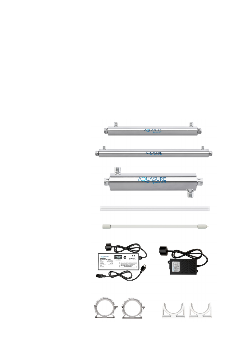
Note: The UV lamp inside of the disinfection system is rated at an effective life of approximately
9000 hours. To ensure continuous protection, replace the UV lamp annually.
SAFETY INSTRUCTIONS

7
OPERATION PARAMETER
IMPORTANT: The following conditions for feed water supply must be met
or warranty will be void and the manufacturer assumes no responsibility
for damage to system or property.
1. Water Temperature Parameter
The system MUST NOT be installed in an area where it is exposed to direct
sunlight and must be protected against freezing and extreme heat.
• Maximum: 100° F (37.8° C)
• Minimum: 32° F (0° C)
2. Water Pressure Parameter
The maximum allowable inlet water pressure is 125 psi. If daytime pressure
is over 80 psi, night time pressure may exceed the maximum allowed water
pressure. Use a pressure reducing valve (PRV) to reduce the pressure if
needed.
• Maximum: 125 PSI (8.78 kg/cm2)
• Minimum: 25 PSI (1.75 kg/cm2)
3. Water condition tolerance
Water passed through the unit must fall within the following parameters:
a) Iron: <0.3 ppm (0.3 mg/L)
b) Hardness*:<7 ppm (120 mg/L)
c) Turbidity: < 1 NTU
d) Manganese: < 0.05 ppm (0.05 mg/L)
e) Tannins: < 0.1 ppm (0.1 mg/L)
f) UV Transmittance: > 75% (call factory for recommendations on
applications where UVT < 75%)
* Where total hardness is more than 7 gpg, the water should be softened.

8
SYSTEM INSTALLATION
STEP 1
1. Shut off the main water supply valve. Locate the main water supply valve of
the house and turn off completely by turning the shut-off handle clockwise.
2. Test to see if the water is completely shut off by turning on the closest faucet
in the cold water position. If the cold water cannot be shut off, please contact
your local plumber to x the valve before beginning system installation.
STEP 2: Mounng the UV System
1. Remove the disinfection system components from the shipping carton. For
shipping purposes, the UV lamp and quartz sleeve are packed in separate
packaging tubes inside the main carton to avoid damage during transit.
IMPORTANT: Leave the lamp and quartz sleeve inside the packaging and
set aside for use later in the installation process.
2. Horizontally or vertically position the UV system to the desired mounting
location. Ensure that there is enough clearance for the system and future
maintenance and removal of the UV lamp. Ideally the clearance should
consider the length of the UV lamp and the ballast prong connector.
IMPORTANT: It is recommended that the Quantum UV system be
mounted in a vertical position. This ensures optimal contact time for the
UV wavelength inside the UV chamber to sterilize contaminants.
Quantum UV
IMPORTANT:
Mounting location should allow
adequate space for removing
the UV lamp and quartz sleeve
components for maintenance.
AS-UV8S Model
shown as reference.
System LengthClearance for replacing
the UV Lamp

9
Quantum UV
Quantum UV
Mounting Surface
Mounting Surface
3. Fasten the UV chamber system to a suitable mounting surface with the
provided system mounting clips.
IMPORTANT: Make sure the inlet and outlet ports on the UV chamber are
clear from any obstruction and plumbing can be routed to the location of
the install.
4. Before connecting plumbing lines assemble the unit and install the quartz
sleeve and UV lamp.

10
STEP 4: System Assembly
IMPORTANT: During the assembly and handling of
the quartz sleeve and UV lamp it is recommended to
wear plastic gloves. DO NOT touch the quartz sleeve or
UV lamp with bare hands. Fingerprints can reduce the
performance of the UV lamp.
1. Remove the unit from the mounting surface and place the
system on a at, stable surface to assemble.
2. Locate and remove quartz sleeve and UV lamp from the
packaging. If necessary, wipe all ngerprints from quartz
sleeve and lamp with isopropyl alcohol and a dry cotton cloth or paper towel.
3. Locate and remove both end caps from the UV system by unscrewing them
counterclockwise.
STEP 3: Connecng the UV System
IMPORTANT: On copper plumbing systems, be sure to install a grounding
wire between the inlet and outlet piping to maintain grounding.
WARNING! Any solder joints being soldered near the valve must be done
before connecting any piping to the system. Always leave at least 6” (152
mm) between the UV system and joints being soldered when soldering
pipes that are connected to the UV system. Failure to do this could cause
damage to the UV system.
1. The UV system is equipped with 3/4” male NPT connections (18GPM unit is
equipped with 3/4” Female NPT and 1” Male NPT). It is recommended that
these connections are made using 6-10 wraps of plumber’s tape.
2. The ow of the water can go either direction depending on the location.
3. Connect the inlet and outlet of the UV system using appropriate ttings.
Important! Make sure the inlet and outlet connection does not interfere
with the replacement of the UV lamp and quartz sleeves.

11
Quantum UV
4. Insert the quartz sleeve into the UV chamber.
IMPORTANT: The quartz sleeve is
fragile and should be handled with care.
Positioning the UV chamber vertically
and slowly lowering the quartz sleeve into
the UV chamber. This method can avoid
the sleeve making contact with the inner
surface of the UV chamber.
IMPORTANT: Leave
equal amount of the
quartz sleeve exposed
on either end of the
chamber.
5. Insert and seat the white pressure seal into the innermost position of the end
cap. Gently roll on the black o-ring over the end of the quartz sleeve. Do this
for both sides of the exposed quartz sleeve and both end caps.

12
7. Locate the UV lamp and connect the ballast plug to the lamp electrical prongs.
IMPORTANT: Do not turn on the system at this time and do not plug into
a wall outlet. Never expose or look at the UV lamp that is powered on.
Doing so can cause damage or loss of vision.
IMPORTANT: Handle the UV lamp gently to avoid damage or breaking the
glass lamp or quartz sleeve.
Open end
cap attached
to power
Closed end
cap
6. Determine which end of the UV system will be on top or will be receiving
power and connected to the ballast. Designate and install the open end cap on
this side of the UV system.
IMPORTANT: Hand tighten the end caps onto the UV chamber.
Overtightening or tightening with the use of tools could result in damage
to the quartz sleeve.

13
8. With the ballast plug connected to the UV lamp slowly and carefully insert the
UV lamp into the open end cap and into the quartz sleeve.
IMPORTANT: The UV lamp is fragile and should be handled with care.
Slowly lower the UV lamp into the end cap and into quartz sleeve can
prevent the glass components from making contact with each other and
preventing breakage.
Quantum UV
9. Attach the ballast plug sleeve over the end cap. Ensure that is fully seated to
avoid the lamp from disconnecting .

14
STEP 5: Flushing and tesng the plumbing lines
WARNING! If the system is leaking at all, turn the unit to the bypass
position and shut off main water supply before assessing leak.
IMPORTANT: Flushing the system lines is necessary to ensure that all
plumbing work has been done correctly, that there is no debris or air
trapped in the piping, and that there are no leaks.
1. Locate the nearest faucet and remove aerator (faucet screen) if there is any.
Turn the cold water position on at the nearest faucet and slowly turn on the
main water supply. Let the water run for a few minutes or until the system is
free of any air or foreign material.
2. Make sure there are no leaks in the plumbing system before proceeding and
shut off the nearest faucet when water runs clear.
STEP 6: System Startup
1. Plug the AC adapter into a nearby wall outlet.
2. A LED indicator on the ballast should start to glow green indicating that the
lamp is turned on and the system is in operation.
WARNING! If the LED indicator on the ballast is not showing any color,
check the wall outlet to make sure it has power. Make sure to unplug the
power supply anytime if removal of UV lamp is required.

15
Your system is ready to use. Please document the system installation date and
replace the UV lamp in the suggested replacement time.
Be sure to register your system within 60 days of purchase. Scan the QR code
below or go to aquasureusa.com/warranty to register your system.
Scan to register your system
CONGRATULATIONS!

16
Quartz Sleeve Replacement And/Or Cleaning:
If the water contains any hardness minerals (calcium or magnesium), iron or
manganese, the quartz sleeve will require periodic cleaning. To remove the quartz
sleeve, rst the UV lamp as outlined above:
1. Shut off water supply and drain all lines.
2. Drain the UV chamber (use a small bucket under the unit to prevent a
spill), using drain port provided.
3. Remove nuts from chamber, checking for the free oating spring inside
sleeve at the opposite end to the lamp connection (do not allow quartz
sleeve to fall).
4. Carefully remove O-rings from the quartz sleeve. As the O-ring may
tend to adhere to the quartz sleeve, it is recommended to replace the
O-rings annually.
5. Clean the quartz sleeve with a cloth soaked in CLR, vinegar or some
other mild acid and then rinse avoiding the introduction of any water to
the inside of the sleeve.
6. Re-assemble the quartz sleeve with spring in the UV chamber allowing
the sleeve to protrude an equal distance from chamber.
7. Wet the O-rings and slide onto each end of the quartz sleeve.
8. Reassemble the gland nuts (hand tight is sufcient).
9. Re-tighten all connections, turn on water and check for leaks.
Re-install the UV lamp and lamp connector as per prior instructions
10. Reconnect system to power source.
Note: If the system is put on a temporary hold, bypassed, removed,
or if it becomes contaminated after the disinfection system, It will be
necessary to shock the system with household bleach for a full 20
minutes before resuming use of the water.
OPERATION & MAINTENANCE

17
UV Lamp Replacement And/Or Cleaning:
WARNING! Regularly inspect your disinfection system unit to ensure the UV
light is still glowing. Replace the UV lamp annually to ensure a high bacteria
and virus kill rate.
IMPORTANT! During the assembly and handling of the quartz sleeve and or
UV Lamp it is recommended to wear plastic gloves. DO NOT touch the quartz
or UV lamp with bare hands. Fingerprints can reduce the performance of the
UV lamp.
1. Disconnect the power
2. Shut off water supply and drain all lines.
3. Pull the UV lamp off of the chamber while it is still connected to
the ballast line.
4. Disconnect the old UV lamp from the ballast.
5. Connect the ballast plug to the new UV lamp electrical prongs.
6. Reinsert the lamp back into the chamber carefully.
7. Turn on the water supply and check for leaks.
8. Reconnect the power
Note: If the system is put on a temporary hold, bypassed, removed,
or if it becomes contaminated after the disinfection system, It will be
necessary to shock the system with household bleach for a full 20
minutes before resuming use of the water.

18
SYSTEM WARNING & TROUBLESHOOT
Lamp Failure System
The audible alarm and indicator lights on the systems continuously monitor the
lamp operation. If the lamp does not start at any time, the indicator red light will
glow and audible alarm will sound. This alarm indicated the UV lamp is no longer
operating and must be corrected. Please refer to Troubleshooting Guide for
corrective procedures.
Ultraviolet Monitoring System
The ultraviolet system features a complete warning system for continuous
water protection by constantly sensing the UV light operation. The system
features a single LED indicator light, which will operate two distinct colors, GREEN
and RED. When the
UV output level changes, the warning system will operate in the following manner:
Indicates that the UV lamp is satisfactory and the unit is in good
working order.
Indicates that the unit needs immediate attention, the audible
alarm will automatically sound when the LED monitor light
switches to red if the lamp has been in service for a year or more
it should be replaced. The quartz sleeve and/or sensor probe
may require cleaning. The alarm will continue until the sensor
detects adequate UV intensity. When the lamp is replaced it is
recommended to clean the quartz sleeve and sensor probe prior to
returning the system to service.
THIS ADVANCED WARNING SYSTEM HAS BEEN
INSTALLED TO PROVIDE YOU WITH THE OPTIMUM
PRECAUTIONS TO ENSURE HIGH EFFICIENCY IN
THE PROTECTION AGAINST MICROBIOLOGICAL
CONTAMINATION IN YOUR WATER. DO NOT
DISREGARD THE WARNING LIGHTS.
THE BEST WAY TO CHECK UV OPERATION IS TO HAVE THE WATER TESTED FOR
BACTERIA BY A RECOGNIZED TESTING AGENCY ON A REGULAR BASIS.
RED
GREEN

19
WARNING! When there is no ow, the water in the cell will become warm, as
the UV disinfection system lamp is always on. To remedy this, run cold water tap
anywhere in the house for a minute to ush out the warm water.
As the system requires time to reach its full operating capacity, please allow the disinfection system to operate
3-5 minutes prior to using the water from unit. In addition, to clear any air or debris form the system, open the
faucet and allow water to run through the disinfection system for 2-3 minutes.
Troubleshoong Guide
CAUTION: When performing any work on the disinfecon system unplug the unit rst and
never look directly at the burning UV lamp.
SYMPTOM POSSIBLE CAUSES REMEDY
PRESSURE
DROP
The sediment pre-lter is
clogged
Replace lter cartridge with appropriate
ve micron cartridge. NOTE: Check source
of water supply as uctuations may occur in
source pressure
HIGH
BACTERIA
COUNT
Quartz sleeve is stained
or dirty
Clean sleeve with scale cleaner and
eliminate source staining problem
The UV lamp is spent Replace UV lamp
Change in feedwater
quality
Have the source water tested to ensure it
is still within the allowable parameters for
use with this unit
Contamination after
disinfection system
It is imperative that the efuent water
stream be shocked with chlorine after the
water leaves the disinfection system the
disinfection system must have a bacteria
free distribution system to work effectively
WARM
PRODUCT
WATER
Common problem caused
by infrequent use Run water
WARM WA-
TER APPEARS
“MILKY”
Caused by air in the water
lines Run water until air is purged
UNIT
LEAKING
WATER
Problem with O-ring seals
(on gland nuts and/or
sensor probe on monitored
units)
Ensure the O-ring is in place, check for cuts
or abrasions, clean O-ring, moisten with
water and re-install, replace if necessary
Condensation on reactor
chamber caused by
excessive humidity
Check location of disinfection system and
control humidity
Inadequate inlet/outlet
port connections
Check thread connections, re-seal with
Teon tape and re-tighten

20
SYSTEM STATUS
REMARKS
LAMP
STATUS
(GREEN LED)
AUDIBLE
ALARM UV LAMP
ON OFF ON Correct operating conditions, unit is
functioning properly
OFF ON OFF The UV lamp is spent, requires replacement
lamp.
UV lamp not connected to power source.
Check connection and reconnect lamp.
Ballast has switched off. To reset ballast
remove power to unit by disconnecting
power cord from electrical plug for a
minimum of 30 seconds then reapply power.
LED indicator burnt out or wire lead broken.
Replace LED assembly.
OFF OFF ON LED indicator burnt out or wire lead broken.
Replace LED assembly.
WATER CHEMISTRY
Water quality is extremely important for the optimum performance of your UV
system. The following levels are recommended for installation:
• Iron:<0.3 ppm (0.3 mg/L)
• Hardness *:< 7 ppm (120 mg/L)
• Turbidity: < 1 NTU
• Manganese: < 0.05 ppm (0.05 mg/L)
• Tannins: < 0.1 ppm (0.1 mg/L)
• UV Transmittance: > 75%
(Call factory for recommendations on applications where UVT < 75%)
* Where total hardness is more than 7 gpg, the UV unit should operate efciently provided the
quartz sleeve is cleaned periodically. If total hardness is over 7 gpg, the water should be softened.
If your water chemistry contains levels in excess of those mentioned above, proper
pre-treatment is recommended to correct these water problems prior to the installation
of your UV disinfection system. These water quality parameters can be tested by your
local dealer, or by most private analytical laboratories. Proper pre-treatment is essential
for the UV disinfection system to operate as intended.
Table of contents
Languages:
Other AquaSure Water Filtration System manuals
Popular Water Filtration System manuals by other brands

Anchor
Anchor AF-6001 Quick setup guide

R-Can
R-Can Sterilight S12Q Installation instructions and owner's manual

3M
3M AP903 Series Installation and operating instructions

Fabri-Technic
Fabri-Technic SF-5 quick start guide

Millipore
Millipore ICW-3000 user manual

GrowMax Water
GrowMax Water ECO GROW 240 quick start guide