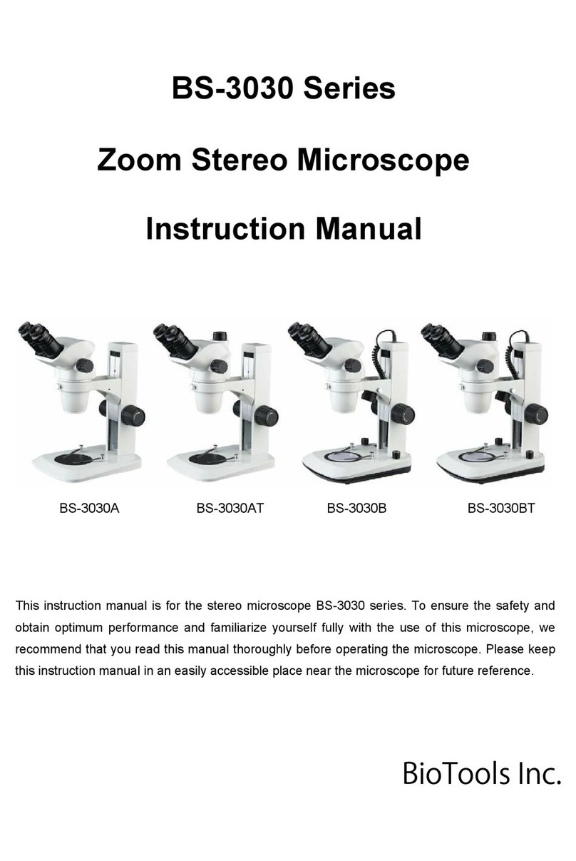
BioTools BS-3047 Series User manual

BS-3047, BS-3048 Series
Zoom Stereo Microscope
Instruction Manual
This instruction manual is for the BS-3047, BS-3048 series stereo microscopes. To insure safety and obtain
optimum performance and familiarize yourself fully with the use of this microscope .We recommend that you read
the manual thoroughly before operating the microscope, Attain this manual instruction in an easilyaccessible place
near the microscope for the further reference.
BioToolsInc.

BestScope International Limited
1
Attentions!!
1) Purpose
The series microscopes are used only for microscopic observation, not for other purpose, otherwise
may cause damage.
2) Disassembled only by the professionals
The microscopes have been adjusted before shipping, Unprofessional-person should not disassemble
and remove any parts.
3) The proper usage
Power supply voltage must be consistent with the input voltage marked in the microscope. If beyond
this range, equipment will be seriously damaged. Microscope is a precision instrument and should be
operated carefully, operators should comply with appropriate safety procedures and assume
responsibility for the safe use of this instrument.
4) Use in safe way, prevent burns and fire
When the illumination is on, temperature of bulb and collector will rise sharply, so pay attention to
anti-hot logo, to prevent burns.
Do not use alcohol, gasoline, paper and other combustibles near the instrument, to prevent a fire! !
5) Notes on replacing the bulb
The correct bulb must be used as the same specification of the bulb in the microscope. Use of other
bulbs may damage the equipment. Before replacing the lamp, must turn off power switch, and
unplug it in order to avoid electric shock and damage to equipment. When replacing the lamp, be
careful not to pollution bulb. The bulb shouldn’t have dust , fingerprints, oil, etc..
The power supply must be cut off before bulb replacement. The bulb must be cooled down
completely before proceeding! !
6) Requirements for handling and using environment
Power must be cut off before moving. Be careful not to crush your finger when placed.
This instrument is a precision instrument, and it should be handle withcare, severe shock cancause
serious damage to equipment-related parts.
The required available environment for using of the equipment:
Indoor temperature: 0 ℃~ 40 ℃
Maximum relative humidity: 95%
High temperature or high humidity may cause mildew, fog or dew of the optical components.
7) For the protection of the environment, please properly handle the microscope packing waste (such
as: cardboard, foam, etc.)
8) Statement
Our company reserves the right to improve product design and outfits.

BestScope International Limited
2
CONTENTS
1. Parts Name...........................................................................................................3
2.Observation procedure..........................................................................................5
3.Operation.............................................................................................................. 6
3.1 Stand............................................................................................................... 6
3.2 Main body.......................................................................................................6
4. Outfit.....................................................................................................................10
5. Technical specification......................................................................................... 11
6. Installation............................................................................................................ 12
6.1 Installation diagram......................................................................................12
6.2 Installation Details ......................................................................................13
7. Optional accessory................................................................................................15
7.1 LED Ring light or Cold light source with Ring Optical Fiber .................. 15
7.2 Polarizing unit.............................................................................................. 15
8. Troubleshooting....................................................................................................16
9. Maintenance and clean......................................................................................... 16

BestScope International Limited
3
1. Parts Name

BestScope International Limited
4

BestScope International Limited
5
2.Observation procedure
2.1 Preparation
1. Check parts
2. Check eyepiece if correctly inserted into tube
3. Prepare for light source
2.2 Procedure
1. Put sample on stage
2. Adjust interpupillary distance
3. Adjust diopter
4. Adjust Zoom knob①to minimum level, rotate the
focusing knob②for coarse focus.
5. Rotate the zoom knob①to the required magnification,
then focus with focusing knob.

BestScope International Limited
6
3.Operation
3.1 Stand
3.1.1 Usage of stage round plate
In order to more easilyobserve samples in reflecting
illumination,Stage plate ①can be changed from white side or
black side.
◎
Ground glass plate can be used with transmitting
illumination
3.1.2 Focusing knob adjustment
Holding left& right focusing knob②withboth hands(Fig 1),
then fixed left focusing knob, rotating clockwise the right
focusing knob, Strain can increase otherwise decrease.
◎
Suggestion:
Set tension at higher position in case of automaticdown.
3.1.3 Usage of light source (Only for stand withillumination)
1. Plug in power cable in socket ③(Fig 1), turn on the power.
2. Turn on power switch ①(Fig 2), transmitted light will be bright.
3. Rotate down illumination wheel②(Fig 2) to adjust brightness.
4. Rotate the top illumination ③for adjusting the light position.
3.2 Main body
3.2.1. Interpupillary Distance Adjustment (Fig.3)
Holding binocular eyepiece tube①, adjusting eyepiece field
until left &right field overlap totally.
◎
The noise is normal when rotating the eyepiece tube to
adjusting field.
3.2.2. Dioper adjustment (Fig 4-5)
◎
Different operation ways depend on whether use reticule eyepiece.
* Not Use Reticule Eyepiece.
1. Make left & right eyepiece diopter adjustable ring ①to
“0” position.
2. Put sample on the stage plate.
3. Rotate zoom knob②to min. magnification power, then
focus the sample with focusing knob③.
4. Rotating zoom knob②to max.zoompower, then focus
the sample with focusing knob③.
5. Rotating zoom knob②to min. zoompower, to focus the
sample with left & right eyepiece diopter adjustable ring ①.
Fig 1
Fig 2
Fig 3
Fig 4
Fig 2

BestScope International Limited
7
* Use Reticule Eyepiece.
1. With micrometer eyepiece to observation, rotate diopter
adjustable ring ①to focus the scale.
2. Put sample on the stage plate.
3. Rotate zoom knob②to low magnification power, focus the
sample with focusing knob③to observe the sample with
micrometer eyepiece.
4 . Rotate zoom knob②to maximum power, then focus the
sample with focusing knob③.
5. Rotate zoom knob②to minimum power, to focus the
sample only with eyepiece diopter adjustable ring ①without
reticule .
◎Notice or Writedown diopter number on the left& right
eyepiece.
10X Eyepiece diopter scale (Fig 6)
◎Useful range from -5 to +5 or over +5 to -5. Whether
over -5 or below +5, both can confirm by eyepiece length.
3.2.3 Usage of zoom magnification limiter(Fig 7)
◎
By using limiter(indicate magnification value) and zoom
knob spacing ring, Magnification can be limited in the
required range. Right zoom knob is used to limit the high
magnification, left zoom knob is used to limit the low
magnification .
1. Use hexagon wrench to loosen right spacing ring’s
①screw ④, it can rotate. (same way to loosen
left ring)
2. Rotate right zoom knob②, the maximum
magnification can in alignment with
indicator(limiter) ③.
3. Make spacing ring①close to limiter ③,Using
hexagon wrench to fasten screw for fixed
condition.
4. Rotating right zoom knob②, the minimum
magnification can in alignment with
indicator(limiter) ③, in the same way to fix
spacing ring.
Fig 5
Fig6
Fig 7

BestScope International Limited
8
3.2.4 Usage of eyecup (Fig 8)
Using eyecup: First to open the folding cover by following
direction of arrow in case of touching eye or scraping eyepiece.
Don’t use eyecup: Put it in normal folding position in case of
external light between eyepiece and eyes.
3.2.5 With additional objective (Fig 9)
◎Because 0.5X additional objective has long working distance,
bracket②must adjust to higher position.
1. With 5mm allen wrench①to remove bracket②screw(up
illumination lamp should be moved from the stand).
2. Moving the bracket②to higher position and fasten the screw.
◎Screwing additional objective into the hole at the bottom of the
microscope.
3.2.6 Storing for allen wrench (Fig 10)
Cover on arm stand canhold 5mm and 3mm allen wrench.
Storing hole is convenient for next use.
Fig 8
Fig9
Fig 10

BestScope International Limited
9
3.2.7 Choose light path (Trinocular main body) (Fig11)
1. Through binocular light path to observe sample, please
turn the switching knob①to IN. (Fig 11)
2. Through camera light path, please turn the switching
knob①to OUT. (Fig 11)
Because in this position ,mirror inserted into the light
path , so 100% left eyepiece tubelight distribution will
pass video output.
3.2.8 Adjusting camera parfocality (trinocular main
body) (Fig 12)
◎Keep parfocality between image and video camera
monitor for better image output after switching
light path.
1. Adjust eyepiece diopter to focus ( Fig. 6-7).
2. Rotate the switching knob①to OUT, set
minimum magnification .
3. Hold camera ③, rotate adjustable knob②, adjust
parfocality to focus for monitor image.
◎
Jointing one 0.5X C-mount with the bottom of the camera .
Monitor image rotation.
For TV light path,The monitor image will rotate slightly because Left
eyepiecelight path is in inclined way.
Rotating camera, monitor image will align at observation image.
(loosening locking screw④and rotating camera, then monitor image is
coincided withobservation image, fasten the locking screw④).
Fig 11
Fig 12

BestScope International Limited
10
4. Outfit
Items
BS-3047B1 BS-3047B3 BS-3047T3 BS-3048B1 BS-3048B3 BS-3048T3
Main Body
(0.68X-4.7X)
Binocular ● ●
Trinocular ●
Main Body
(0.68X-4.7X)
Binocular ● ●
Trinocular ●
10XEyepiece/Φ23mm ● ● ●
10XEyepiece/Φ24mm ● ● ●
20XEyepiece/Φ12mm ○ ○ ○ ○ ○ ○
0.5X/2X Objective ○ ○ ○ ○ ○ ○
Eyeguard ● ● ● ● ● ●
Focusing unit ● ● ● ● ● ●
No light ● ●
Reflecting 3W LED ● ● ● ●
Reflecting 5W LED ○ ○ ○ ○
Transmitting 3W LED ● ● ● ●
Black & white Plate ● ● ● ● ● ●
Glass Plate ● ● ● ●
Arm stand ● ● ● ● ● ●
Pillar stand ○ ○ ○ ○ ○ ○
Base (330×300mm) ● ● ● ● ● ●
Polarizing Unit ○ ○ ○ ○ ○ ○
Fine focusing unit ○ ○ ○ ○ ○ ○
C-mount 0.5X ● ●
C-mount 1X ○ ○
Adapter for digital photo camera ○ ○
Two dimensional travelling table ○ ○ ○ ○ ○ ○
Single pole Universal Stand ○ ○ ○ ○ ○ ○
Note: "●" In Table Is Standard Outfits, "○" Is Optional Accessories.

BestScope International Limited
11
5. Technical specification
BS-3047 Series
Additional Objectives 0.5X 0.75X 1X(built-in) 1.5X 2X
Working distance (mm) 184mm 108mm 40mm
10X Eyepiece
/φ23mm
magnification 3.4~23.5 5.1~35.3 6.8~47 10.2~70.5 13.6~94
Field dia(mm) 67.65~9.75 45.1~6.52 33.82~4.89 25.55~3.26 16.91~2.45
15X Eyepiece
/φ17mm
magnification 5.1~35.3 7.65~52.9 10.2~70.5 15.3~105.8 20.4~141
Field dia(mm) 50.0~7.23 33.33~4.82 25.0~3.62 16.67~2.41 12.5~1.81
20X Eyepiece
/φ13mm
magnification 6.8~47 10.2~70.5 13.6~94 20.4~141 27.2~188
Field dia(mm) 38.24~5.53 25.49~3.69 19.12~2.77 12.75~1.84 9.56~1.38
BS-3048 Series
Additional Objectives 0.5X 0.75X 1X(Built-in) 1.5X 2X
Working distance (mm) 184mm 108mm 40mm
10X Eyepiece
/φ24mm
magnification 3.3~25.5 5.0~38.3 6.6~51 9.9~76.5 13.2~102
Field dia(mm) 72.73~9.41 48.48~6.27 36.36~4.71 24.24~3.14 18.18~2.35
15X Eyepiece
/φ17mm
magnification 5.0~38.3 7.4~57.4 9.9~76.5 14.9~114.8 19.8~153
Field dia(mm) 51.52~6.67 34.34~4.44 25.76~3.33 17.17~2.22 12.88~1.67
20X Eyepiece
/φ13mm
magnification 6.6~51 9.9~76.5 13.2~102 19.8~153 26.4~204
Field dia(mm) 39.39~5.10 26.26~3.40 19.70~2.55 13.13~1.70 9.85~1.27
* When use 0.5X auxiliary objective, the focus arm should be changed to upper position of the square rail pillar
stand.
◎No matter the zoom magnification, the working distance of same objective willnot change.
◎Use the following formula to calculate Total magnification and field of view
Total magnification = Zoom Magnification × Eyepiece Magnification × Auxiliary Objective Magnification
FOV=Eyepiece FOV / (Zoom Magnification× Auxiliary Objective Magnification*)
* Without Auxiliary Objective, this value is 1

BestScope International Limited
12
6. Installation
6.1 Installation diagram (Note: Number is installation sequence )
★To ensure that all parts has no dust and dirt. Note any part not scratch, rub or touch the glass
surface.

BestScope International Limited
13
6.2 Installation Details
6.2.1 Main body Installation (Fig.13)
1. Unscrew body locking screw
①
, insert main body
②
.
2. Fasten the Body Locking screw ①.
◎You can rotate the main body if making observation
from one side of focusing knob.
6.2.2 Eyepiece Installation (Fig.14)
1. Turn eyepiece
②
to 0°, then insert into the eyepiece
tube, line is up (if choose ordinary eyepiece, no such
step).
2. Fasten the eyepiece locking screw ①with socket head
wrench.
Fig 14
Fig 13

BestScope International Limited
14
6.2.3 Stage plate installation (Fig 15)
1. Insert the stage plate (2) to slide on the spring of the
bed plate
①
, then make the plate into the mounting
hole and press from top to down to make it firmly
installed.
◎
According to different sample to chose white plate
cover or black plate cover.
2. Please remove the plate directly with finger following
the diagram .
6.2.4 Camera installation(Only apply to trinocular
body)(Fig 16)
1. Connect C-mount
②
and adapter ring
③
.
2. Screw in the combination adapter to the camera.
3. Loosen the locking screw
⑤
, insert the camera and
lock again.
4. Connect the data cable from monitor or computer to
camera.
Fig 15
Fig 16

BestScope International Limited
15
7. Optional accessory
7.1 LED Ring light or Cold light source with Ring Optical Fiber
7.1.1 Installation (Fig 17)
1. Screwing the ring lamp jointing ring in main body.
2. Connecting the ring light source and fasten the
locking screw.
7.1.2 Usage
1. Switch on the power after installing the illumination.
2. Uselight dimmer to change the illumination
brightness.
7.2 Polarizing unit
7.2.1. Installation
1. Put the analyzer in the bottom of the microscope head.
2. Put the polarizing film in the stage hole.
3. Install the glass plate (Fig 15).
7.2.2 Usage
The polarizing unit must be used with transmitting illumination
unit.
Focusing for samples: rotate analyzer for best illumination effect,
light intensitycan be changed by using the down illumination
dimmer Knob.
Fig 17

BestScope International Limited
16
8. Troubleshooting
Trouble
Causation
Remedy
Page
Left &right field of view
can’t overlap.
Interpupillary distance adjustment
isn’t correct.
Readjust 6
Optical parallax isn’t correct. Readjust 6-7
Left & right Eyepiece is different. Change eyepiece with
same magnification. 3
Dust found in view image. Dust on sample. Wipe the dust 16
Dust on eyepiece.
Image isn’t clear. The dust on the top of the objective. Wipe the dust 16
When changing focus and
magnification power,
sample image is out of
focus.
Eyepiece diopter isn’t accurate. Re-adjust again. 6-7
Focusing adjustment isn’t correct. Focusing again. 5
Image in Right field or
image in monitor became
two half.
Light path switch knob isn’t at IN
position.Turn switch knob to IN. 9
Monitor image is out of
focus .
Incorrect focusing adjustment for
camera. Focusing again. 9
9. Maintenance and clean
9.1 If the lens surface has dust, please clear with a blow ball. If the lens surface with fingerprints or
oil stain, please clean gently with absorbent cotton or lens paper dipped in a little ethanol ether
mixture (ratio 1:4) .
Absolute alcohol is an inflammable material, please turn off the power and don’t close to cause
fire, Please assure indoor ventilation.
9.2 Don’t use solvent to wipe non-glass parts unless with soft hairless cotton in little neutral
cleanser.
9.3 Don’t disassemble microscope parts, otherwise result in damage for performance.
If you have any question, please contact us or our local distributor.
BestScope International Limited
Add: 3# 1101, Zi Yu International, No.2 Yin He South Street,
Shi Jing Shan District, Beijing, China 100043
Tel: +86 10 88689701
Fax: +86 10 88689701
Email:info@bestscope.net
http://www.bestscope.net
http://www.digital-opticalmicroscope.com
This manual suits for next models
1
Table of contents
Other BioTools Microscope manuals
Popular Microscope manuals by other brands
BestScope
BestScope BS-2094 Series instruction manual
Vision
Vision Mantis Compact user guide

Olympus
Olympus CX21 instructions
Swift
Swift M29TZ-SM99CL-BTW1 use and care manual
Bresser Junior
Bresser Junior 8855000 operating instructions
Ken A Vision
Ken A Vision Dual Purpose Scope 2 T-19311C instruction manual

