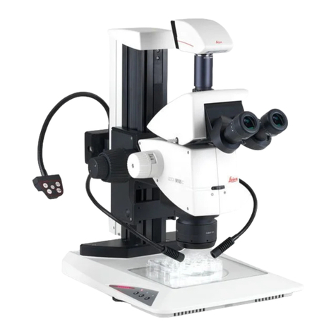
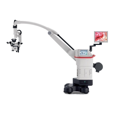
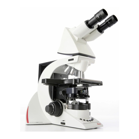
Leica WILD M690 User manual


Service manual M690x Legal questions / Safty-Rechtsfragen /Sicherheit
11/93 3688-BZ
Inhaltsverzeichnis / Table of Contents
Kapitel
Seite
Rechtsfragen / Legal questions ..................................................................................... 1
Question juridiques / Cuestiones de derecho.................................................................. 2
Sicherheit / Safety / Securite / Seguridad ......................................................................
3

Liability
Service manual M690 Legal questions / Safty-Rechtsfragen / Sicherheit
11/933688-BZ
Copyright
Ohne vorherige schriftliche Erlaubnis der Firma Leica AG, Heerbrugg (Schweiz), darf dieses Dokument
weder insgesamt noch auszugsweise mit mechanischen, fotografischen, elektronischen oder irgendwelchen
anderen Mitteln (einschließlich ihrer Umwandlung oder Übertragung in maschinenlesbarer Form) kopiert,
in einem Informationsspeicher abgelegt, außerhalb des dafür vorgesehenen Zwecks oder in irgend einer
Form an von Leica AG, Heerbrugg nicht ausdrücklich befugte Dritte zugänglich gemacht oder abgegeben
werden
Haftung
Dieses Dokument richtet sich ausschließlich an qualifizierte Servicetechniker und Servicetechnikerinnen,
welche über die notwendigen Fachkenntnisse verfügen
Qualifizierte Servicetechniker und Servicetechnikerinnen sind solche, die den entsprechenden Servicekurs
bei Leica AG, Heerbrugg erfolgreich besucht haben und bei Unternehmen der Leica Gruppe oder bei von
Leica AG, Heerbrugg autorisierten Vertretungen oder Servicewerkstätten tätig sind
Wird dieses Dokument von nicht qualifizierten Servicetechniker und Servicetechnikerinnen verwendet, so
lehnt Leica AG, Heerbrugg jegliche Haftung ab für direkte und indirekte Schäden, die durch nicht
fachgemäße Anwendung und/oder Interpretation dieses Dokumentes entstehen
Copyright
Without prior permission in writing by Leica AG, Heerbrugg (Switzerland), this document shall not be
reproduced as a whole or in part, by mechanical, photographic, electronic, or other means (including into or
transmission in machine-readable form); stored in any retrieval System; used for any purpose other than
that/those for which it is intended; nor made accessible or communicated in any form to any third party not
expressly authorized by Leica AG, Heerbrugg to have access thereto.
‘Ibis document is strictly for the use of qualified service engineers with the requisite technical skills.
Only persons who have successfully completed the appropriate service training provided by Leica AG,
Heerbrugg and are in the employ of a Company in the Leica Group or of an agency, distributor, or Service
workshop duly authorized by Leica AG, Heerbrugg have the status of qualified Service engineer.
Leica AG, Heerbrugg accepts no liability whatever for direct or indirect darnage that may occur due to the
unauthorized or improper use or interpretation of this document by any person who is not a qualified
service engineer in accordance with the above definition.
Service manual M690 Legal questions / Safty-Rechtsfragen / Sicherheit
11/93 3688-BZ
Sie verstehen und befolgen die Sicherheitsinformationen und die Instruktionen auf dem Produkt sowie in
der Gebrauchsanleitung.
Sie kennen die ortsüblichen gesetzlichen, betrieblichen und ausserbetrieblichen
Unfallverhütungsvorschriften im Wissen, dass sich diese auf dem aktuellsten Stand befinden.
Sie benachrichtigen Leica schriftlich, sobald an der Ausrüstung Sicherheitsmängel auftreten.
Service technicians have the following obligations:
l
To understand
and follow the safety information and instructions on the product and in the user manual.
l
To
be familiar with local regulations relating to industrial and non-industrial accident prevention in the
knowledge that these regulations are up to date.
l
To inform
Leica immediately in writing if the equipment becomes Unsafe.

INHALTSVERZEICHNIS
CONTENTS
Testbox M690
Testbox M690
TRIEBKASTEN
DRIVE HOUSING
Focus Zoom Board, Mikroschalter
Focus Zoom Board, Microswitches
Focusmotor
Focusmotor
Spindel, Rollenführung
Threaded spindle, roller bearing
OPTIKTRÄGER
OPTICS CARRIER
Seite/Page
1,2
Demontage Triebkasten vom Optikträger
Seperate Drive housing and optics carrier
Platine mit Zoomantrieb
Plate with zoom drive
Platine mit Zoomantrieb justieren
Adjust plate with zoom drive
3-5
6
7,8
9-11
Ober-und Unterteil trennen
Seperate upper-and lower part
12,13
14-22
23-25
Zoomeinheit
Zoom assembly
26-30

1
INSTRUKTIONEN FÜR DEN ELEKTRISCHEN TEIL DES M690 SIND ENTHALTEN IM:
INSTRUCTIONS FOR THE ELECTRICAL PART OF THE M690 AR INCLUDED IN:
S E R V I C E M A N U A L M E L 2 7 / 4 6
TESTBOX M690
Mit
der Testbox M690 können der Zoom-und Focusmotor und die Lampe ohne die Steuereinheit MEL27
betrieben werden. Notwendig ist ein Netzgerät
Spannung
=
Stromstärke =
12V
min. 2A
By using the M690 test box the zoom and focusing motor and the lamp can be set to work Without the
control unit. A power supply unit is necessary in addition to the test box
VoItage
=
12v
Current
=
min. 2A

2
Anschluss Triebkasten und Optikträger an Test-
box.
Connection of drive housing and optic carrier to the
testbox.
Anschluss Triebkasten an Testbox.
Connection of drive housing to the testbox.
Anschluss Optikträger an Testbox.
Connection of optics carrier to the testbox.


Focus Zoom Board (A) anheben und 3 Stecker (B)
(P17,18,19) au
sziehen und Focus Zoom Board demon-
tieren.
Montagehinweis:
- Beim Einstecken der Stecker auf Kordierung achten.
- Schaltpunkte der Mikroschalter S1 und S2 einstellen.
Siehe Seite 5.
Lift up Focus Zoom board (A) , pull out 3 plugs (B)
(P17,18,19) and remove Focus Zoom Board.
Assembly instruction:
- Ensure that the coded plugs are correctly inserted.
- For adjustment of switch point of the microswitches
S1 and S2, see page 5.

Mikroschalter Schaltpunkte einstellen.
1. Der untere Schalter S2 muss schalten, wenn die
untere Fläche des Schlittens (A) 1,5mm über
der unteren Fläche der Führungsleiste (B) steht.
2. Der Schaltpunkt des oberen Schalters S1 muss so
eingestellt sein, dass der Weg des Schlittens mind. 45mm
beträgt.
Korrekturen:
Schalter S1 oder S2 nach unten oder oben schieben.
Adjust switch points of microswitches;
1. Switching at the lower switch S2 must occur when
the lower face of carriage (A) is 1,5mm above the
lower face of the guide ledge (B).
2. The switch point of the upper switch S1 is correctly
adjusted when the carriage moves min. 45mm.
Correction:
Slide switch S1 or S2 up or down

Die Demontage des Triebkastens vom Optikträger ist nicht für alle Servicearbeiten notwendig
Do not separate drive housing and optics carrier for any Service work.
4 Schrauben (A) , Triebkasten (B) und Distanzplatte
(C) demontieren. Kabel (E) durch Schlitz (D) ziehen.
Montagehinweis:
Mit Winkel (F) und Platte (G) Triebkasten rechtwinklig
zur Tubusauflage ausrichten.
Remove 4 screws (A) , drive housing (B) spacer plate
(C) and pull out cable (E) through slit (D) .
Assembly instruction:
Align drive housing with bracket (F) and plate (G) at
right angle to supporting face of tube.

- Mit Durchschlag (A) Spindel (B) festhalten und
Mutter (C) ausschrauben.
- U-Scheibe (D) und Zahnrad (E) demontieren.
Hinweis:
Bei einigen Instrumenten der 1. Serie ist die
Spindel länger. Siehe Foto (1) . Bei diesen
Instrumenten muss zum Demontieren des
Zahnrades die Spindel nach unten geschoben
werden.
-Hold spindle (B) with pin punch (A) and unscrew
nut (C) .
- Remove washer (D) and gearwheel (E) .
Note:
A longer spindle (B) is fitted in some instruments
of the firse production series. (see illustration (1))
In these instruments the spindle must be moved
downwards before removing the gearwheel (E) .

8
Montagehinweis:
- Durch Verschieben von Motor (E) Zahnradeingriff
einstellen.
- Flansch (B) mit Nute (C) in korrekter Position
montieren.
Assembly instructions:
- Adjust clearance of gear wheel by displacing motor (E)
- Fit flange (B) with slot (C) in correct Position.

9
Deckel (A) Gewindering (B) und Gewinde-
Spindel (C) ausschrauben.
Unscrew cover
(A) , threaded ring (B) and threaded
spindle (C) .

Montagehinweis:
-U-Scheiben (B) mit beschichteter Seite zur Mutter (C)
montieren.
-Nute (D) zur Mitnehmerschraube orientieren.
-Bohrung (E) zu Gewindeloch orientieren.
Mutter (C) muss sich verschieben lassen, darf aber kein
vertikal Spiel aufweisen.
Assembly instructions:
-Fit washers (B) with coated side to nut (C) .
-Align slot (D) to drive screw
-Align hole (E) to tapped hole. Nut (C) must slide sideways
but there must be no vertical backlash.
4 Schrauben (F) und Balg (G) demontieren.
Remove 4 screws (F) and bellows (G) .

Montagehinweis:
-Führung (A) gegen Anschlag (B) drücken und 3 Schrauben
anziehen.
- Mit 3 Schrauben (C) Führung (D) anstellen bis sich das
Rollenlager schwer verschieben lässt.
Assembly instructions:
-Press guide bar (A) against stop (B) and tighten 3 screws
- Clamp guide bar (D) with 3 screw (C) until roller
bearings moves hard.

Hinweis:
Ober und Unterteil des Optikträgers können auch mit montiertem Triebkasten getrennt werden.
Note:
Upper and lower parts can also be separated without removing drive housing.
Montagehinweis:
Kurze Distanzbüchsen (A) bei Schutzblech (B) , lange Distanzbüchsen (C) bei Schutzblech (D) montieren.
Assembly instructions:
Mount short spacer bushes (A) to Protective cover (B) and long spacer bushes (C) to protective cover (D) .

13
Kondensorschlitten (A) mit Trieb (B) ganz nach vorne
schieben und Oberteil nach oben abheben.
Montagehinweis:
-Der Schlitz (C) muss in den Stift des Kondensorschlittens
eingreifen.
- Auf gute Verbindung der beiden Stecker (D) und (E)
achten.
Turn drive knob (B) to move condenser slide (A) com-
pletely forward and lift up upper part.
Assembly instructions:
- Slit (C) must engage in pin of condenser drive.
-Ensure that plugs (D) and (E) are properly connected.
Table of contents
Other Leica Microscope manuals