Bircher Reglomat PrimeTec A User manual

I
1
PrimeTec A
PrimeScan A
Start-up
2Mounting
Translation of the original instructions
Recommendedstart-upsequence:I.MountingII.ConnectionIII.Initialisation
Mounting
*Factory setting
General
Safety instructions
1
The width of the AIR field can be set using the click-in plastic cover in front of
the detector's lens. (Dimensions at 2.2 m mounting high)
Detector without cover:
All light beams are active
Setting the AIR field width (PrimeTec / PrimeScan)
Possible field width settings:
2.1
Pleasekeepforfurtheruse!
Field width:
2.3 x 0.2 m
Quality
international
level
EN ISO
9001
*
ENGLISH
Observe the national and international regulations on door safety.
Only trained, qualified personnel may mount and start up the detector.
The unit may only be opened and repaired by Bircher Reglomat.
The unit may only be operated from a safety extra-low voltage (SELV) system with safe electrical separation.
Always consider the safety functions of your application as a whole, never just in relation to one individual section of the system.
The installer is responsible for carrying out a risk assessment and installing the detector and the door system correctly.
Avoid touching any electronic components.
The door drive and transom profile must be earthed correctly.
Hood
LED display
AIR light window
Detector without hood
LCD display
Microwave module
optics-cover
Detector electronic
Mounting holes
Cable bushing
a Button Mode (red)
b Button Data (black)
AIR adjusting device
LED1 AIR: red (left)
LED2 Microw.: green (rig.)
PrimeTec A
PrimeScan A
PrimeTec
PrimeScan
1. Remove cover hood 3. Lay and connect cable
2. Set AIR field width (see chapter 2.1) 4. Mount detector
A, B, G, H covered E, G, H covered C, D covered
1. Slide
A, D covered A, B, D covered E, F covered
2. ush & click!
ABCDEFGH
A, B, G, H covered
A. B, G, H covered
Feldgrösse: 0.25 x 0.2m
1.
2.
Field width: 1.3 x 0.2 m Field width: 0.25 x 0.2 m
Field width:1x0.2m Field width:1x0.2m
Field width: 0.75 x 0.2 m Field width: 0.75 x 0.2 m
Field width: 0.25 x 0.2 m Field width: 0.25 x 0.2 m
Mounting of the detector
2.2
1. Position drill template
2. Drill the holes, remove drill template
3. Lay cable and mount detector
Combined detector AIR/Radar for opening and
protecting automatically controlled sliding doors
ab

II
Initialisation
Mechanical fine tuning
Electrical connections
Connecting
Initialisation
III
Once the detector has been connected to the power supply, it can be configured via the
Reglobeam within the next 30 minutes. Following initialisation, the red/green LED only lights up
when a detection has occurred. The door system has been taken into operation at this point.
If any further settings or calibrations are required, proceed as described in the following section.
Remove the current supply all objects that do not form part of the usual door system environment from the door area BEFORE switching on.
Make sure that no-one is in the door area, otherwise correct startup will not be possible.
3
5
4
The alternate flashing shows the initialisation «teaching» of the detector. (Duration 20 - 25 sec.)
6Configurationwith Reglobeam remote control (referto Reglobeam operatinginstructions)
Remote control: Basic functions of the remote control:
IR interface Function Start
key
Functio
n key(s)
Num er
key(s)
Display on
remote control
Function of the
remote control Notes
Establishing
the connection none none Continuously lit
flashes
Connection to the detector
No connection to the
detector
If flashes, hold the remote
control closer to the detector and
point it more directly at the
detector, also check the batteries.
Establishing
the connection
with address
selection
none
–
It is not
possible
to access
by Re-
globeam.
and the number of
the selected number
key
Address = Number of
the selected
number key
If flashes, no connection,
If and all numbers light up,
no configuration mode is acti-
vated.
PrimeTec / PrimeScan Controller
white
brown
green
yellow
grey
pink
blue
red
Cable
white
brown
green
yellow
grey
pink
blue
red
Power Supply
–
+
RAD output –
+
Test –
+
AIR output –
+
–
+
11.5 - 32 VDC
GND
+In
GND
+ In
GND
+In
PrimeTec A ES / PrimeScan A * Controller
1 white
2brown
3green
4yellow
5 grey
6rose
7 blue
8red
Cable
white
brown
green
yellow
grey
rose
blue
red
Power Supply
–
+
Radar output –
+
Test –
+
AIR output –
+
–
+
11.5 - 32 VDC
3 m
–
+
–
+
–
+
Radar IN
Test
AIR IN
Number
keys
Function
keys
7Configuration by hand (Operator buttons)
1m
2m
3m
1m
2m
0m
0m
1m
2m
2.2 m
1m
2m
3m
1m
2m
0m
0m
1m
2m
2.2 m
red LED green LED
*) Value is going to be saved by switching to other parameters
* For other versions (eg. PrimeTec A ES.SM.V) see supplementary sheet
–+
5.1
5.2 Radar field ( rimeTec)
AIR-field ( rimeTec / rimeScan)
––
++
––
++
Manual settings of the inclination
0° ... +90° in 5° steps
Settings of the inclination angle on the
adjustment screw:
Inclination: -5° – +7° continuously
adjustable
Manual settings of the pivoting
-20° ... +20° in 5° steps
––
++
+
–
Round radar field Wide radar field
min. = 0.5 x 0.5m (WxD)
max. = 2.7 x 1.9m (WxD) min. = 1.1 x 0.6m (WxD)
max. = 4.7 x 1.7m (WxD)
0°
+ 1 … + 7°
– 1 … – 5°
Automatic Config. mode Choose Choose Funct./ arameter Back to choice Back to autom.
1 2
1 2
1 2
1
1 2
Detector in
automatic mode
Press both
buttons
simultaneously
Red button:
switch Black button:
choose
Red button:
Choose
parameter *
Black button:
Choose value of
the parameter
Press both
buttons Press both
buttons
Operator buttons
red (Mode) &
black (Data)
General
LCD
Radar AIR
➝ see table parameter 3 ➝ see table parameter 3

General functions ( rimeTec / rimeScan) O ERATION OF THE BUTTONS 1REGLOBEAM (REMOTE CONTROL) 2
Parameter (Mode) Value (Data) LCD Mode Significance of num er keys
Reset Press oth uttons 8 seconds –Initialisation
Connection ––– += Switch off configuration mode by Reglobeam. Switching on by access code or power cut.
Comfort settings 11 – 8
12
*= Standard, = foot path, = home for the aged, = wind screen,
= high door, = narrow door, = wide door, = factory settings
Activate / not activate combined outputs 21 – 2
12
+ = activated (AIR or radar actuate both outputs)
* = not activated
Reglobeam addresse (communication
remote control detector) 31 – 6
2
1
+ * = Address 1, = Address 2, = Address 3, = Address 4, = Address 5, = Address 6
In the case of overlapping AIR fields consider the addressing order: ➝odd number ➝ even number ➝ odd numberl
Access code (By pressing oth operating uttons simultaneously it can e switched to the
configuration mode ot the general functions) On
Off
+
+
Status Save
+ + lit = off Choose code (1111 - 9998) Press
+ + lit = on Press 4 x Press
3
For all values set,
parameter 0is
displayed
*Factory sett.
Radar functions ( rimeTec) O ERATION OF THE BUTTONS 1REGLOBEAM (REMOTE CONTROL) 2
Parameter (Mode) Value (Data) LCD Mode Significance of num er keys
Field width 11 – 5
1
= Smallest radar field, ......., * = Medium radar field ,......, = Largest radar field size
Direction recognition 21 – 3
1
+ = Off, * = Forwards = Backwards
Field geometry 31 – 2
1
+ = round radar field, min. = 0.5 x 0.5m (WxD), max. = 2.7 x 1.9m (WxD)
* = wide Radarfeld, min. = 1.1 x 0.6m (WxD), max. = 4.7 x 1.7m (WxD)
Cross Traffic Optimisation 41–5
1
+ = Off, * – Low, – High (–= Sensitivity values for cross traffic masking)
(Expedient only at narrow field)
SMD field width (Slow Motion Detection) 51 – 5
1
+ * = Off, = Low, = Standard = Largest SMD field
Door filter (Interfence for radar) 61 – 4
1
+ * = Filter off, = Door filter on (Movements of the door),
= Inteference filter on (EMV flows, e.g. fluorescence tube) , Door and interference filter on
Radar exit 71 – 3
1
+ * = active, = passive, = Radar off
AIR functions ( rimeTec / rimeScan) O ERATION OF THE BUTTONS 1REGLOBEAM (REMOTE CONTROL) 2
Parameter (Mode) Value (Data) LCD Mode Significance of num er keys
Set sensitivity 11 – 4
2
+
– high sensitivity (Indoor application acc. DIN 18650), mounting height 3 ≤ 3.5m (full field width)
*– Middle sensitivity (Outdoor application acc. DIN 18650), mounting height 3 ≤ 3.0m (full field width)
– low sensitivity (DIN 18650), mounting height 3 ≤ 2.5m (1m field width), – Extra low sensitivity
Set teach-in time 21–5
2
+ = 10 s, = 30 s, * = 60 s, = 180 s, = 15 min
AIR exit contact logic 31 – 2
2
+ = high, * = low
= Logic like test input = contrary logic as test input
AIR exit 41 – 2
2
+ * = on, = off
1Press oth uttons shortly for configuration mode // 2Press start key
efore switching on the comfiguration mode. / The green LED lights up quickly when receiving data // 3see planning aids for mounting height

4
263672F 03/11
1
1
2
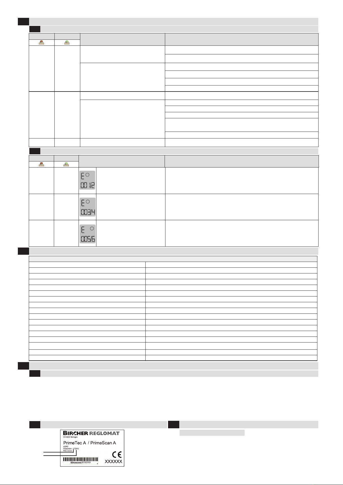
Identification of the year of manufacture
10.2
Year of
manu-
facturing
Week
red LED green LED Fault Remedy
dark continu-
ously lit
Radar tripping when door is closing 1. Set angle of radar further away from the door.
2. Adjust radar field size.
Radar false tripping without
apparent external influence
1. Avoid light sources (e.g. fluorescent tubes) in the immediate vicinity of the detector.
2. No moving objects (e.g. plants, advertising posters, etc.) in the vicinity of the detector.
3. Avoid strong vibration at the radar detector
4. Possible influence from a second radar detector in the vicinity (very unlikely)
continu-
ously lit dark
AIR tripping when door is closing 1. Set angle of AIR detector further away from the door
AIR false tripping without apparent
external influence
1. Avoid light sources (e.g. fluorescent tubes) in the immediate vicinity of the detector.
2. Avoid puddles of water on the ground.
3. Avoid strong vibration at the AIR detector.
4. Influence of overlapping AIR field from another detector.
Set new Reglobeam address or CAN bus address.
5. Reduce sensitivity of the AIR.
dark dark Door stays open 1. Switch AIR exit contact logic to other value
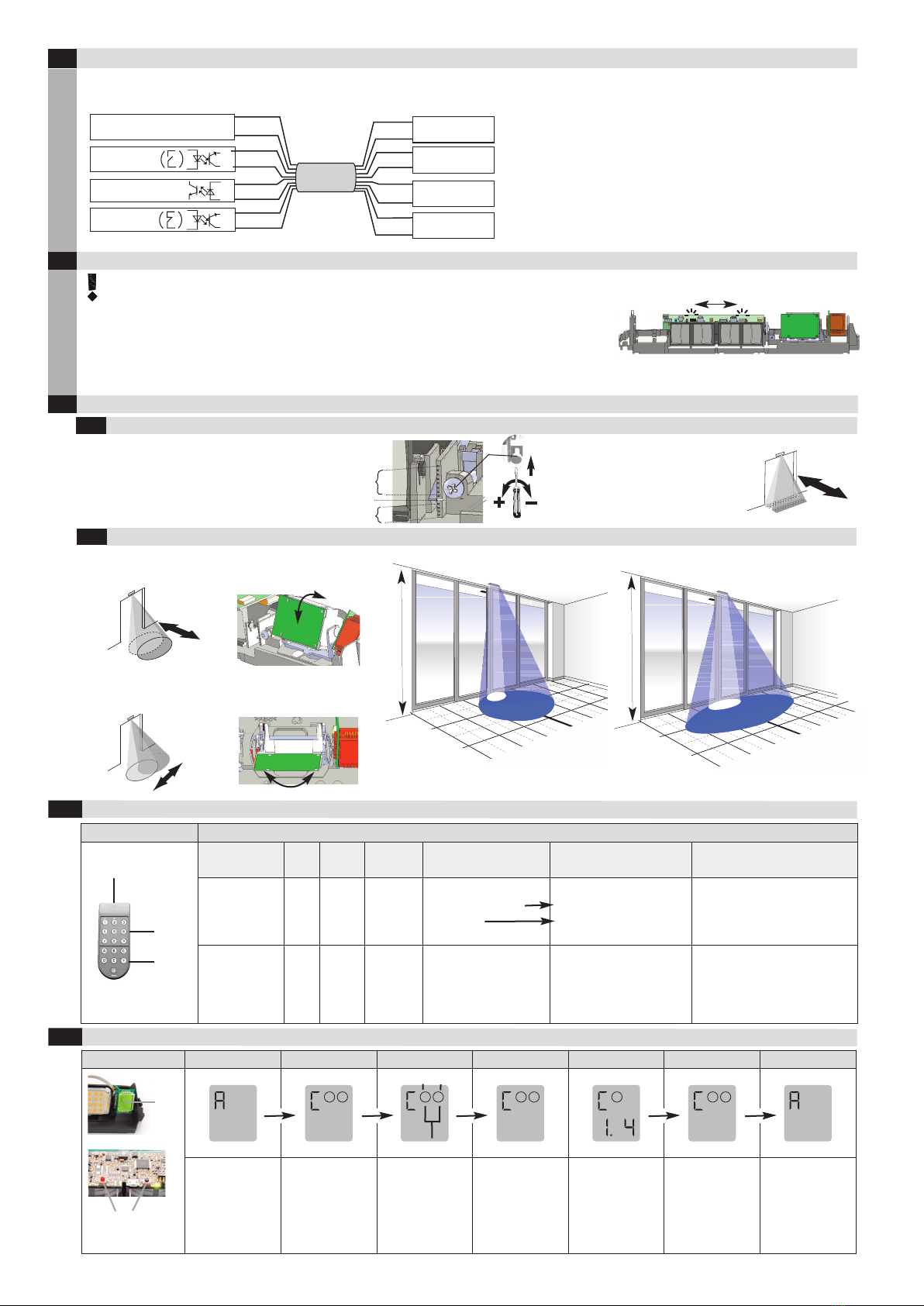
flashing dark 1: Self test (RAM/ROM)
2: Watchdog
1. Disconnect device from supply voltage
2. Clean lens
3. Restart device
4. If device displays fault again or does not start ➝renew device
dark flashing 3: Radar fault
4: Radar exit fault (SM)
1. Disconnect device from supply voltage
2. Check plug on microwave module
3. Restart device
4. If device displays fault again or does not start ➝renew device
flashing dark 5: AIR fault
6: AIR exit fault
1. Disconnect device from supply voltage
2. Restart device
3. If device displays fault again or does not start ➝renew device
Remedying malfunctions
8
Most important technical data
9
Declaration of conformity, identification of the year of manufacture by means of the serial number
10
11 Contact data
Manufacturer:
Bircher Reglo at AG
Wiesengasse 20
CH-8222 Beringen
Switzerland
www.bircher-reglo at.co
Remedying false tripping
8.1
Remedying detector malfunctions
8.2
Declaration of conformity
10.1
red LED green LED LCD Fault Remedy
PrimeTec / PrimeScan
Technology Active infrared (wavelength: 880nm), radar double field module ➝ PrimeTec (24.125 Hz)
Number of IR spots 36
IR spot dimensions 3 cm x 3 cm (at 2.2 m mounting height)
Response time < 200 ms
Mounting height 1.8 – 4 m
Angle setting of IR spots 5° - 7° continuously adjustable
Electrical power supply ≤120 mA @ 11.5 – 32 VDC
Power consumption < 4 watts
Making current ≤240 mA
Output (AIR / Radar) Optocoupler (50 VDC, 50mA)
Protection class Suitable for use acc. to IP54
EMC / RTTE acc. to EMC and RTTE directives
Remote control range 3 m
Operating temperature - 20° to 60° C
Dimensions PrimeTec: 260 x 60 x 48.5mm (LxWxD), PrimeScan: 216 x 60 x 47.5mm (LxWxD)
Weight PrimeTec: 250g, PrimeScan: 180g
Life cycle 20 years
Manufacturer: Bircher Reglomat A , Wiesengasse 20, CH-8222 Beringen, Switzerland, www.bircher-reglomat.com
Authorised rep: Bircher Reglomat mbH, Robert Bosch Strasse 3, D-71088 Holzgerlingen, ermany
Notified Body: TÜV NORD CERT mbH, Langemarckstrasse 20, D-45141 Essen, NB 0044, EC-type-examination certificate No. 44 205 10 554810
Following directives have been observed: 2006/42/EC, R&TTE Directive 1999/5/EC, EMV-Directive 004/108/EC
Following standards have been taken into account:
EN 61000-6-1,
EN 61000-6-2, EN 61000-6-3, EN 61000-6-4, DIN 18650-1:2005, EN 12978:2003+A1:2009,
EN ISO 13849-1:2008, Cat. 2/PLd (AIR) & Cat. 3/PLd (Radar), IEC 61494-1, AutSchR, 1997/BS7036-1 & BS7036-2
Signee: CEO, L. Oberholzer / QHSE, K. Kuhn / 20.5.2010, CH-8222 Beringen
Product variant: PrimeTec A ES, PrimeScan A, PrimeTec A ES/01, PrimeTec A ES.SM.V, PrimeTec A.SM.F, PrimeTec A.SM/01, PrimeTec A.SM/02, PrimeTec A.SM/03
This manual suits for next models
1
Other Bircher Reglomat Garage Door Opener manuals
Popular Garage Door Opener manuals by other brands

Genie
Genie INTELLIG 1000 3024H Operation and maintenance manual

moore o matic
moore o matic XX325 Assembly and installation instructions

tau
tau 650ESE03 installation instructions

LEXMAN
LEXMAN WSS50-10-L instruction manual

Chamberlain
Chamberlain BASIC-ML510EV Assembly and operating instructions

Beninca
Beninca BRAINY manual

Aprimatic
Aprimatic ONDA 2000 installation instructions

KING
KING Dynamos 500 instruction manual

Chamberlain
Chamberlain T owner's manual

Chamberlain
Chamberlain 90-5024 installation instructions

Alutech
Alutech Levigato LG-600F-868 Assembly and operation manual

moore o matic
moore o matic Z133a Series Homeowner's installation and operation manual