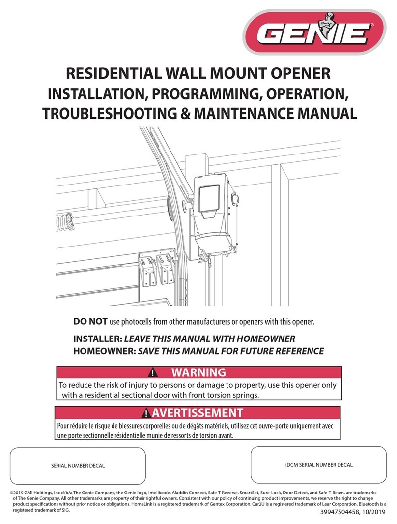
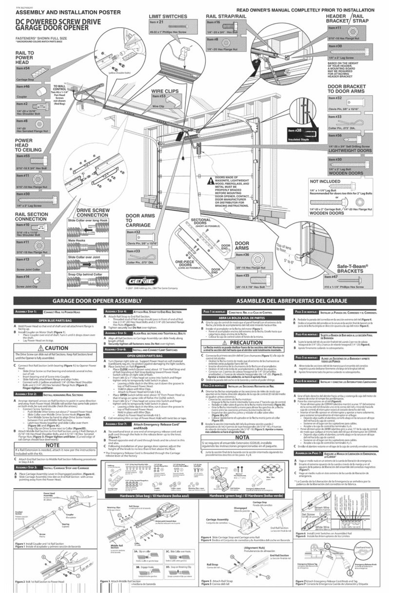
manuals.online logo
Brands
  1. Home
  2. •
  3. Brands
  4. •
  5. Genie
  6. •
  7. Garage Door Opener
  8. •
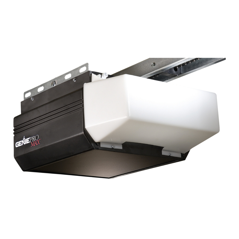
  9. Genie DirectLift 2060 User manual

Genie DirectLift 2060 User manual

Other manuals for DirectLift 2060

1

This manual suits for next models

1

Other Genie Garage Door Opener manuals

Genie DirectLift 2060 User manual

Genie

Genie DirectLift 2060 User manual

Genie 38416A.S Use and care manual

Genie

Genie 38416A.S Use and care manual

Genie GCL-GT User manual

Genie

Genie GCL-GT User manual

Genie GCL-GT User manual

Genie

Genie GCL-GT User manual

Genie Wireless Keypad User manual

Genie

Genie Wireless Keypad User manual

Genie GPS-IC Series User manual

Genie

Genie GPS-IC Series User manual

Genie genie manuals-instructions Installation instructions

Genie

Genie genie manuals-instructions Installation instructions

Genie 2042 User manual

Genie

Genie 2042 User manual

Genie Intellicode 1022 User manual

Genie

Genie Intellicode 1022 User manual

Genie 2562 Programming manual

Genie

Genie 2562 Programming manual

Genie 1035 Manual

Genie

Genie 1035 Manual

Genie POSTER Programming manual

Genie

Genie POSTER Programming manual

Genie INTELLIG 1000 3024H User manual

Genie

Genie INTELLIG 1000 3024H User manual

Genie Intelligent Wall Console User manual

Genie

Genie Intelligent Wall Console User manual

Genie SAFE-T-BEAM SYSTEM User manual

Genie

Genie SAFE-T-BEAM SYSTEM User manual

Genie H User manual

Genie

Genie H User manual

Genie Excelerator User manual

Genie

Genie Excelerator User manual

Genie Protectrix18M Assembly instructions

Genie

Genie Protectrix18M Assembly instructions

Genie IntelliG 1200 User manual

Genie

Genie IntelliG 1200 User manual

Genie TriloG 1200 Series User manual

Genie

Genie TriloG 1200 Series User manual

Genie GCL-GT User manual

Genie

Genie GCL-GT User manual

Genie PowerMax 1200 Manual

Genie

Genie PowerMax 1200 Manual

Genie GCL-MT User manual

Genie

Genie GCL-MT User manual

Genie M-4500 User manual

Genie

Genie M-4500 User manual

Popular Garage Door Opener manuals by other brands

ATA GDO-6 EasyRoller instruction manual

ATA

ATA GDO-6 EasyRoller instruction manual

CAME F4000 Series installation manual

CAME

CAME F4000 Series installation manual

Garaga SECURITY+ 3265GCM 1HP owner's manual

Garaga

Garaga SECURITY+ 3265GCM 1HP owner's manual

Chamberlain Whisper Drive SECURITY+ WD822K Series owner's manual

Chamberlain

Chamberlain Whisper Drive SECURITY+ WD822K Series owner's manual

Chase Doors DuraShield installation manual

Chase Doors

Chase Doors DuraShield installation manual

CSI Classic installation instructions

CSI

CSI Classic installation instructions

Chamberlain Elite 3575S owner's manual

Chamberlain

Chamberlain Elite 3575S owner's manual

Richmond GTR156 user manual

Richmond

Richmond GTR156 user manual

B&D Controll-A-Door 5 instruction manual

B&D

B&D Controll-A-Door 5 instruction manual

Chamberlain MyQ 940ESTD owner's manual

Chamberlain

Chamberlain MyQ 940ESTD owner's manual

Automatic Technology GDO-9V1 SecuraLift installation instructions

Automatic Technology

Automatic Technology GDO-9V1 SecuraLift installation instructions

Westfalia 19 36 07 instruction manual

Westfalia

Westfalia 19 36 07 instruction manual

Chamberlain HD520EVP manual

Chamberlain

Chamberlain HD520EVP manual

Cardin BL Series instruction manual

Cardin

Cardin BL Series instruction manual

Chamberlain 8355 - 1/2 hp installation instructions

Chamberlain

Chamberlain 8355 - 1/2 hp installation instructions

Bauer CROSS18 Application. Installation and Maintenance Manual

Bauer

Bauer CROSS18 Application. Installation and Maintenance Manual

Dorma ES 90 manual

Dorma

Dorma ES 90 manual

Wayne-Dalton 8124 Installation instructions and owner's manual

Wayne-Dalton

Wayne-Dalton 8124 Installation instructions and owner's manual

manuals.online logo
manuals.online logoBrands
  • About & Mission
  • Contact us
  • Privacy Policy
  • Terms and Conditions

Copyright 2025 Manuals.Online. All Rights Reserved.

©pe_'at et} and
e3559935907
2060
3060
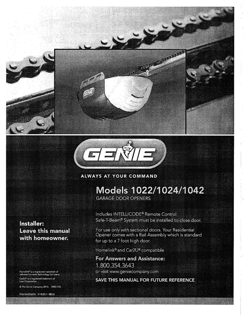
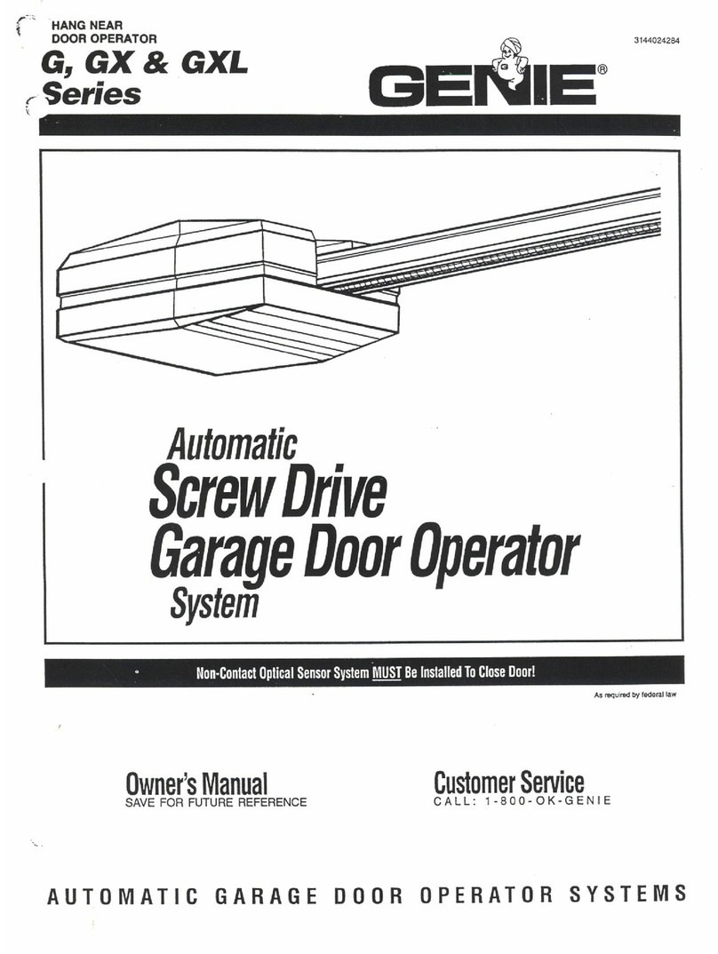
AC POWERED SCREW DRIVE OPENERS
COHTEHTS
Warranty Information ...................2
Your Documentation Package ..........3
Safety Information ..................... 4
Safety Features ......................... 4
Important Installation Instuctions ....... 4
Pre-lnstallation Checklist .............. 5-8
Adjustments ......................... 9-10
Programming the Remote Control ..... 11
Installing lightbulb and lens ............ 12
Scheduled Maintenance ............... 13
Troubleshooting Guide ............. 14-15
Wiring Diagram ........................ 16
Parts Lists and Exploded Views ...... 17-18
Accessories ............................ 19
(k)MRLETE WITH II,_I"ELLICO[}E
!E!OTE COST ;;'_r_ AH© ,<I_;D_ ........,J RuL s ,sES II
For up to 7'-6" tall Doors. (Extension Kit available for 8' Doors)
Included Wall Control MUST be installed prior to Operation of
this Garage Door Operator.
Safe-T-Beam ®Safety Reverse System Must be Installed and
the Force Controls MUST be Properly Set to dose door.
This Equipment meets or exceeds all Federal, State and UL325
Safety Requirements.
Please call us: 1-800-3S-GENIE (354-3643)
www.geniecompany.com
Please have Model information
ready when calling.
What s ceve_'ed?
Anydefectin materialandproductworkmanshipfrompersonal,normalhouseholduse
inaccordancewiththeOwner'sManual.
Fo_'hew o_9?
MODEL2060L...20 years on motor, 3 years all other parts.
MODEL3060L... Lifetime* on motor,3 years all other parts.
MODEL3060C ... Lifetime _ on motor, 3 years all other parts.
*Lifetime = Foras long asyou own your home.
Who gets rise, v_:_a_s'a_ty
This warranty is limited to the consumer who originally purchased the product.
Thiswarrantyappliesonlyto unitsinstalledandoperatedwithinthe countrywhere
theywerepurchased.
L, ¢_ tat _sns
IMPLIEDWARRANTIES,INCLUDINGTHOSEOF FITNESSFORA PARTICULARPURPOSEAND
MERCHANTABILITY(AN UNWRITTENWARRANTYTHATTHE PRODUCTISFITFORORDI-
NARYUSE),ARELIMITEDTO ONEYEARFROMTHEDATEOF PURCHASE.GENIEWILL NOT
PAYFOR:LOSSOF TIME;INCONVENIENCE;LOSSOF USEOFYOURGENIEPRODUCTOR
PROPERTYDAMAGECAUSEDBYYOURGENIEPRODUCTORITSFAILURETOWORK;ANY
SPECIAL,INCIDENTALORCONSEQUENTIALDAMAGES;ORANY DAMAGESRESULTING
FROMMISUSEOR MODIFICATIONOFYOURGENIEPRODUCT.
Some states and provinces do not allow limitations on how long an implied warranty
lastsor the exclusion of incidental or consequential damages, sothe above limitations or
exclusions may not apply to you.
This warranty isthe only one we will give on your Genie product, and it sets forth all our
responsibilities regarding your Genie product.There are no other express warranties.
State and province rights:This warranty givesyou specific legal rights, andyou may also
haveother rights which vary from state to state and province to province.
How to get wa_'_'a_ty se_'v<e,
To obtain warranty servicefor your Genie product, you must provide proof of the date
and place of purchase of the product.
Call the GenieConsumer Connection toll free at 1.800.354.3643to speakin person to a
trained Genie representative for assistance in diagnosing the problem and arranging
to supply you with the required parts for do-it-yourself repairs.Trained service repre-
sentatives are available Monday-Friday, 8:00 a.m.- 11:00p.m.,Eastern Time, and on
Saturday, 10:00a.m.to 8:00 p.m.,Eastern Time (subject to holidays) You may also get
the information you need at www.geniecompany.com.
You also may obtain warranty service from Genie authorized dealers by calling the
Genie Customer Service at 1.800.354.3643or by visiting www.geniecompany.com
before scheduling warranty service.If warranty service is provided by an authorized
dealer, Geniewill provide all required parts under warranty at no charge to you, but
the dealers are independent businesspeople and may render a bench or service call
charge for their services.Genie will not reimburse you or otherwise be responsible for
those charges.
Wesuggest that you retain your original packing material in the event we choose to
repair or replaqce your Genie Product and request that you ship it to us.Besure to
include your name, address,telephone number, proof of date and place of purchase
and a description of the operating problem.After repairing or replacing, your Genie
product, we will ship it to your home at no cost to you for parts and labor, but you will
have to pay a minimum of %.00 for shipping and handling charges.
Your choice of either one of the above-described serviceoptions isyour exclusive
remedy under this warranty.
What th wa_'_'a_ty does _ot cove_'
This warranty does not cover batteries (which are considered replaceable parts), installa-
tion, commercial use,defects resulting from accidents,damage while in transit to our
service location or damage resulting from alterations, misuse or abuse,lack of proper
maintenance, unauthorized repair or modification of the product, affixing of any attach-
ment not provided with the product, programming of the Remote Control Devices,
Safe-T-Beam®adjustment/cleaning, staples through wiring, pinched or broken wires,
Carriage disengaged, ForceControl adjustments, door out of balance, broken springs
or cables,power outages, use of extension cords, missing or damaged parts on dis-
counted, clearanced, final sale or taped cartons, phantom operations (labor isnot cov-
ered if Opener is functioning properly while technician is in garage),fire, flood, or actsof
God,or other failure to follow the Owner's Manual.
FORANSWERS:CALL1.800.354.3643
Pleasenote the following information,so it isavailable if you
needto call us.
Date Purchased / /
SerialNumber
Operator Model
Remote Control Model
Dealer Name
DealerAddress
City
State
Zip
Model Number and
Serial Number are
located on front
panel inside
the lens.
NOTE
Please keep original or photocopy of your sales
rece!ptwith this manual for future reference should
service ever be required.
Visit Our Website at: www.geniecompany.com
SAVETHESEINSTRUCTIONS

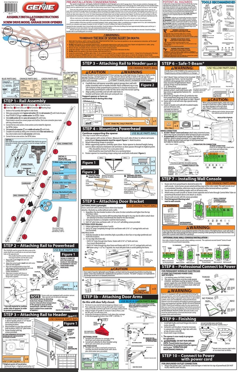
The documentation provided with your opener has been carefully designed and organized to make the assembly, operation,and continued
maintenance of your product as easy and safe as possible.This material consists of two main items.
While it is recommended that all documents be retained for future reference, this manual should contain most of the information that you
will need over the lifetime of your product.The manual is designed in a "flip-flop"configuration with the english version in one half of the
book and the spanish /french version in the other half.The basic contents of this manual are:
i,.ii ", i ,, ..
i}F SIII ¢ a , )A;, A
Warranty Information
Pre Installation Checklist to be reviewed prior to any
assembly or installation
Necessary Adjustments
Programming Remote Devices _e
Maintenance and Troubleshooting
Parts Explosions
Accessory Order Form
Door Opener Association Safety and Maintenance Brochure (DASMA)
Entrapment Warning Label - To be Adhered in close proximity
to wall control
siisl_i _c. ce
%<. SiOl_ <h /c _;,.. i.
iDI=I_iII_
[ ill]q .xl_i(' .i,;'Ksi()l]
Assembly a_'_d/_}stallatio_'_ Peste_
This poster is intended to give a convenient lay flat media to be used at the site of assembly and installation. Color coding is used to
highlight steps and other information as clearly as possible.This poster is Tri-Lingual with english instructions highlighted with a blue
background.The basic contents of this Poster are:
(_e _e
Quick Reference Poster ....................._
Pictorial and step by step opener assembly mstruclons -.- _:_ ......
nsta at on nstruct ons . ,_ .........::........._., _, .Pictorial and step by step opener ........_;'--,
") .... ._.i._., _///'
(> f' /_:o{' / _..........................................
IT IS CRITICAL THAT ALL SAFETY WARNINGS MARKED CLEARLY IN BOTH
THE MANUAL AND POSTER ARE READ, UNDERSTOOD AND FOLLOWED.
The Genie Company is constantly striving to improve our products and the documentation that comes with them. If you have any
suggestions or ideas for improving this product and it's documentation, please forward them to:
The Genie Company
22790 Lake Park Blvd.
Alliance, Ohio 44601-3498
2060-3060 eng.qxd 11/9/05 11:02 AM Page 4 i
'\ b/
........_i]i17.......
OVERVIEW OF POTENTIAL HAZARDS
Overheaddoors arelarge,heavy objects that move with the help of springsunder high tension and electric motors. Sincemoving objects,springs under
tension, andelectric motors can causeinjuries, your safety andthe safetyof others depend on you readingthe information in this manual. Ifyou have
questions or do not understand the information presented, callThe GenieCompany.or your local GenieDistributor.
In this section, and those that follow, the words Danger, Warning and Caution are used to emphasize important safety
information. The word:
.i_ DANGER: indicates an imminently hazardous situation which, if not avoided, will result in death or serious injury.
WARNING: indicates a potentially hazardous situation which, if not avoided, could result in death or serious injury.
-_ CAUTION: indicates a potentially hazardous situation which, if not avoided, may result in injury or property damage.
The word NOTE is used to indicate important steps to be followed or important considerations.
WARNING: • Keep people clear of opening while door is moving.
Could result in death •Do Not allow children to play with the door operator.
or serious injury. • Do Not operate a door that jams or one that has a broken spring.
MOVINGDOOR
ELECTRICALSHOCK
HIGHSPRINGTENSION
WARNING:
Could result in death
or serious injury.
WARNING:
Could result in death
or serious injury.
• Turn off power before removing operator cover.
• When replacing cover, make sure wires are not pinched or near
moving parts.
• Operator must be properly grounded.
•Do Not try to remove, repair or adjust springs or anything to
which door spring parts are fastened, such as,wood blocks,
steel brackets, cables or other like items.
• Repairs and adjustments must be made by a trained door
system technician using proper tools and instructions.
WARNING:
TO REDUCE THE RISK OF SEVERE INJURY OR DEATH:
1 READAND FOLLOW ALL SAFETY,INSTALLATIONAND
OPERATIONINSTRUCTIONS.If you have any
questions or do not understand an instruction, call
your authorized Genie installation professional.
2 Do Not install operator on an improperly balanced
door. An improperly balanced door could cause
severe injury. Repaffs and adjustments to cables,
spring assembly, and other hardware must be made
by a trained service person using proper tools and
instructions.
3Remove all ropes, and disable all locks connected to
the door before installing operator.
4Install door operator 7 feet or more above the floor.
Mount the emergency release knob 6 feet above
the floor.
5 Do Not connect the operator to the source of power
until instructed to do so.
6Locate the control button:
Within sight of door.
At a minimum height of 5 feet, so small children
cannot reach it.
•Away from all moving parts of the door.
7Install the entrapment WARNING label next to the
wall button or console. Install the emergency release
tag on, or next to, the emergency release
8The operator must reverse when the door contacts a
1-1/2 inch high object on the floor at the center of
the doorway.This is about the size ofa 2"x 4" board
laid flat.
Safe-T-Beam ®(STB) Non-Contact Reversing System
Places an invisible beam across door opening, that reverses
the door during down travel to the fully open position if
anything passesthrough beam.
Safe-T-Reverse ®Contact Reversing System
Automatically stops and reverses a closing door within 2
seconds of contact with an object.
Safe-T-Stop ®Timed Reversed System
Automatically opens a closing door, if door does not close
within 30 seconds.
ForceGuard ®Control
Used to set the force required for opening and closing
door. For maximum safety, set the minimum force required
to fully open and close door.
Automatic Lighting System
Light bulbs up to 60 Watts max., used for safer entries and
exits.The lights turn on when door isactivated and
automatically turn off 4.5 minutes later.
Manual Emergency Release
Allows the garage door to be opened or closed manually
for emergencies or maintenance.
4I<_I"Js_<, %%%1,<÷Is_, 01]11-I<_ iiy 1(oI]l
........\X7.......
i
........................._:i ........................
2060-3060 eng.qxd 11/9/05 11:02 AM Page 5 i
'\ b/
This Opener includes parts and supplies needed to install in most garages and
connect to most garage doors. There are many variations of garages and garage
doors. A few additional parts and supplies may be needed to install Opener into
your garage and connect to your garage door. While checking items listed
below, note any additional items you will need.
• 12'+ Tape Measure ° Pencil ° Ladder ° Level
WARNING:
If your door sticks, binds, or is out of
balance, have it adjusted by a Genie Factory
Authorized Dealer. Door springs, cables,
pulleys, brackets and associated hardware
are under extreme tension and can cause
serious injury or death.
........<17.......
Check condition of vertical stile in center of door (Figure 2), and its connection
to door's top and bottom beams.
AIf door frame is nailed together and not a solid connection, door frame
must be braced or reinforced before installing Opener.
BIf door is"lightweight"(made with frame and skin - not solid), door
(including door frame) must be braced or reinforced before
installing Opener.
CA door opener reinforcement bracket may also be needed to connect
garage door to Opener's Door Bracket. This Opener is designed for
installation on a properly braced sectional door or solidly braced
one-piece door.
DContact your Genie Factory Authorized Dealer or dealer of your garage
door for any necessary bracing and a door opener reinforcement
bracket (if needed) before proceeding.
EIf you have a wooden door, measure door's thickness. (1/4" x 2") Lag
Screws are included for installing Door Bracket onto door. If your door
is less than 2"thick, brace door or use shorter Door Bracket Lag
Screws (1/4" x 1-1/4"- not included)
KEEPFEETCLEAR OF DOOR
........<17.......
I;_L 6HP_ZH ] O I_iRAs]"lOF_l
ARaisedoor, check alignment and see if it moves freely (Figure l). Ifdoor
appears out of alignment, binds, or does not move smoothly, contact a
Genie Factory Authorized Dealer or dealer of your garage door for repairs
and adjustments to door mechanism.
BRaise door to 3' - 4' above ground and carefully let go. Door should stay
stationary. Slight movement is acceptable. More than slight movement
means door is out of balance. Contact a Genie Factory Authorized
C
Dealer or dealer of
your garage door
for repairs and
adjustments to door
mechanism.
Check door type.
Make a note of
whether it is a
sectional or a
one-piece door
(Figure 2).
SECTIONALDOOR,TORSIONSPRINGS SECTIONALDOOR,EXTENSIONSPRINGS
Torsion Extension
Header Springs Springs
Figure 1
Center
Stile
Figure 2 Note Door Type
One-Piece Door
Checking door balance
ONE-PIECEDOOR,TRACKLESS
Header Area
Center Stile
5
i
.........................L_IN........................
i
2060-3060 eng.qxd 11/9/05 11:02 AM Page 6
Measure garage door height (7'-6", 8'-0", or taller) with
tape measure.
AIf door height is 7'-6" or less, continue with Check Step 4.
BIf door height is 8'-0", you need a Rail Extension
Kit. (Figure 3) (See Accessories Order Form, page 19).
CIf door height is taller than 8'-O",you will require a different rail.
Contact an Genie Customer Service Representative at 1-800-
35-GENIE.
CH_iG DOO_ M_it%[;@H:{/_:E_
Figure 3 Rail Extension Kit
Rail Extension for
8' door
........\ii7 .......
NOTE
The header isa heavily reinforced section of the wall just
above the top of the garage door opening.
A
B
Find vertical center line of door and header:
•Close door.
• Measure door width at top.
• Mark a point at center of door and on header directly
above door. Draw a center line to connect points.
Find Header Bracket mounting height (Figure 4):
(Do not attach Header Bracket).
• Raise door, watching top edge of door and stop door
when its edge reaches its highest point.
• Measure distance ("H") from top edge of door to floor.
- For sectional doors, add 2-1/2" to"H" Mark a point
on center line. Bottom of Header Bracket will be
installed here.
- For one-piece doors, add 6" to "H" Mark this point on
center line. Bottom of Header Bracket will be
installed here.
HEADER
SECTIONAL DOOR
H
ONE-PIECE DOOR
........\ii7 .......
NOTE
C
6
For both types of doors:
-If the ceiling in your garage is so low that there is
not at least a 3" space above the Header Bracket
mountingpoint, contact a Genie Factory
AuthorizedDealer.
If a door spring isin the way, place the Header
Bracket above the spring. Do Not move the door spring.
WARNING:
Door springs are under extremely high tension and should be
handled ONLY by a trained professional.
Check wall for a stud or a solid header at your mark:
(If checking a finished wall, a stud finder may be helpful).
• If location is above Header, a 2"x 6" board must be
screwed to studs beside your mark with at least two Lag
Screws and Flat Washers (not provided).
• Transfer your mark to new mounting board.
HEADER
H÷6"
Figure 4 Find Highest Point of Travel
.........................L_IN........................
2060-3060 eng.qxd 11/9/05 11:02 AM Page 7 i
Check ceiling or space above where Opener Power Head will be
mounted (Figure S):
AMeasure from garage door center line mark toward rear
of garage:
° Approximately 10' back if garage has a 7' 6" door.
° Approximately 11' back if garage has an 8' 0" door.
NOTE
Since garage construction varies widely, there may be
hardware required in addition to the mounting straps.
BFind location of ceiling joist or truss above where Opener
Power Head will be and estimate type and quantity of
materials needed for your installation (Figure 6).
Check for 15 Amp, 120 Volt
......_ grounded outlet or wiring box
within 3 feet of
'\- S: . &£ Power Head. J
il V//
.... :--T&:.........
.......;"" k]ii':
for 7-1/2'
Figure S Check Power Head location
........\X7.......
MOUNTING EXAMPLES
Perforated Angle Iron Conduit Wood Perforated Straps FINISHED CEILINGS
Locate ceiling joists or trusses
using a stud finder or similar
device.
Attach angle iron (not included
to joists or trusses through
finish material using Lag Screws.
OPEN CEILINGS
Straps and angle iron may attach
directly to joists or trusses.
Figure 6 Mounting methods for open beam or finished ceilings
........\X7.......
ACheck that there is a 15 Amp 120 Volt grounded electrical
outlet or grounded permanent wiring box (per building code)
within 3' of Opener Power Head:
• If not, an outlet or wiring box must be installed. Contact
a licensed electrician for installation.
• If building codes require permanent wiring, Power Head
must be partially disassembled to install appropriate
wiring in place of Power Cord (See Installation Poster).
NOTE
Permanent wiring must be installed by a Licensed
Electrician. Not all Genie Factory Authorized Dealers are
Licensed Electrician's. Contact someone who is a Licensed
Electrician.
7
i
.........................':i ........................
2060-3060 eng.qxd 11/9/05 11:02 AM Page 8 i
(_HECH SAH> -BBJWv _'
MOL/;K_"BY5 [_;_,, ,RE L,OC£]"/OH
Check for wood garage frame, jamb, or masonry at mounting location
(6" above floor) with attachment tabs facing away from garage door
(Figure 7).
AIfyou cannot mount Safe-T-Beam® Mounting Bracket to
wood frame:
• Concrete screws and concrete anchors (not included)
must be used to mount Brackets on masonry with
attachment tabs facing away from garage door.
• Safe-T-Beam ®Mounting Bracket Extensions may be used
(not included - available from a Genie Factory Authorized
Dealer or through Accessories Order Form on page 19).
A
BTools (Figure 8):
Additional tools to make installation easier:
• Slotted and phillips screw-driver bits
° Stud finder
° Sheet-metal cutting snips
Source
Safe-T-Beam ®
Mounting Bracket
Sensor
:2-_--1__-
i]l t = --;=±
J 'hi
i _ilJi ' : ).z_-_ To0o
i ," II 6" Bracket6
II J above
6 Ill floor
_,q_!,J,L
Figure 7 Mounting Safe-T-Beam ® Components
........_]i17.......
Doo_<{Locls
Check that the garage door locks, rope, and T-Handles are removed
from the garage door before starting the installation.
Ifyour garage does not have a separate entry door, it is highly
recommended to install a Genie Emergency Release Kit (GER-2).
Emergency Release Kit lets you open garage door from outside if
there is a power failure. (Please see Accessories Order Form on
page 19.)
Befo_e 9ob_{F u_tBe_)get _y terns _'_d tools
_'_eeded fo_ you_
[] Safe-T-Beam ®Sensor Mounting Bracket Extensions (dealer)
[] Garage door opener reinforcement bracket (dealer)
[] Garage door frame reinforcement brackets, screws, bracing
or reinforcement kits (dealer)
[] Lag Screws (1-1/4") for a wood door less than 2" thick (store)
[] Electrical outlet and/or wiring (supplied by a
licensed electrician)
[] Sufficient angle iron or strapping for hanging Power Head
(store)
[] 60 Watt light bulbs
(Rough service bulbs recommended)(store)
[] GER-2 Emergency Release Kit for entry during power failure
(store)
[] Wood for header, ceiling, and/or door bracing reinforcement
(if needed)
[] Masonry fasteners for Safe-T-Beam ® Bracket installation,
(if needed)
[] Masonry drill bit (if needed)
[] Extension Kit (for 8' garage doors)
Drill
1/16" 5/32"
Drill Bit Drill Bit
6' or 7'
Step Ladder
Adjustable Wrench
Hammer Wire
Stripper
Phillips Screwdriver Wrench
( I_/ I)1
Flat Blade Screwdriver
Safety Glasses
£]
Pencil
888888
1/4" 5/16" 8/8" 7/16" 1/2" 9/16"
Hack Saw Sockets
Carpenter's Level
Figure 8 Recommended Tools
........q17.......
8
i
.........................L_IN........................
2060-3060 eng.qxd 11/9/05 11:02 AM Page 9 i
/i%
........_i]17.......
_£1q _E A q%.,EAHD _E}LtUSTMEKI%
tCOICI 0", , ..... _"_=*
IIougB Setti_'_g of Lissit Swit_:cBes
ASetting Close Limit Switch (Figure 9):
• Check that Carriage Assembly is disengaged.
• With garage door fully closed, slide Close Limit Switch
toward Carriage until white lever is fully lifted.
• Tighten Set Screw. Do Not over-tighten.
BSetting Open Limit Switch:
• Manually open garage door to full open position.
° Slide Open Limit Switch toward Carriage until white lever
is fully lifted.
• Tighten Set Screw. Do not over-tighten.
• Re-engage Carriage Assembly.
kis_it :s,4J c_e,s
WARNING
•The garage door opens rapidly, and cancauseserious
injury or death.
• Keepthe path clear.
• Position the ladder to the side of the Power Head so it is
clear of all moving parts of the Opener and the door.
• Set the door Opener to use the minimum force needed
to open the door.
ACLOSE ADJUSTMENT
• On front panel of Power Head find adjusting screw
marked "CLOSE" (Figure 9).
• Gently turn screw counterclockwise until it stops.
- Very little force is required to turn adjusting screw.
• Press Wall Console to close garage door.
- Observe if door stops at"CLOSE" limit switch.
If door is fully closed--adjustment is finished.
Go to "OPEN" Adjustment.
- If door stops but is not fully closed,
a. Measure distance between bottom of door
and floor.
b. Move "CLOSE" Limit Switch that same distance
toward door.
- If door stops and/or reverses before reaching the
"CLOSE" Limit Switch
a. Slightly increase CLOSE Force setting (clockwise).
- If door reverses after contacting floor, move Limit
Switch toward Power Head.
- If door fails to move, check Safe-T-Beam ®System. See
Troubleshooting Section, page 14.
• Tighten Limit Switch Set Screw. Do not over-tighten
(strip) Limit Switch Set Screw.
NOTE
oLittle effort is required to turn the Force
Adjusting Knobs.
• If the door stops moving while opening or
closing, adjust the Open Force or Close Force
Controls slightly clockwise (to slightly
increase the force) and retry the step.
• The Open Force and Close Force Controls are to
be set to the minimum force necessary to
ensure the door smoothly opens and
closes completely.
• Ensure the Carriage Assembly isengaged and is
between the two Limit Switches before
operating the Opener.
FORCE
CONTROLS
Figure 9 Making Force Adjustments
,/i'%
........\117.......
Open adjustment next page.
9
i
.........................L_IN........................
2060-3060 eng.qxd 11/9/05 11:02 AM Page 10 i
'\ b/
WARNING
• A moving grage door can cause serious injury or death.
• Keepthe path clear.
• Position the ladder to the side of the Power Head so it is
clear of all moving parts of the Opener and the door.
• Set the door Opener to use the minimum force needed
to open the door.
........ki17.......
BOPEN ADJUSTMENT
• On front panel of Power Head find adjusting screw
marked "OPEN" (Figure 9).
• Gently turn screw counterclockwise until it stops.
- Very little force is required to turn adjusting screw.
• Press Wall Console to close garage door.
- Observe if door stops at"OPEN" limit switch.
If door is fully open--adjustment is finished.
-If door stops but is not fuly open,
a. Measure distance between bottom of door
top of door opening.
b. Move "OPEN" Limit Switch that same distance
toward Power Head.
-If door stops before reaching the"OPEN" Limit Switch
a. Slightly increase OPEN Force setting (clockwise).
-If door fails to move, see Troubleshooting Section,
pages 15.
CRun Door Opener
• Cycle opener a few times to double check settings.
Repeat adjustment steps as necessary. ........ki17.......
SITTIH6 <CI _U'_+{°"__= Jl.= &_=
I,_IVIB,sI I<iIIHCTlOH
NOTE
Limit Switch and Force Adjustments must be completed
before checking the contact reverse function (Figure 10 ).
AOpen garage door using Wall Console.
BLay a 2" x 4" board flat in center of doorway.
C Close door using Wall Console.
DCheck that door stops and reverses within 2 seconds after it
contacts board:
• If door does not reverse, decrease Close Force until
door reverses.
• If door still does not reverse, move Limit Switch
toward door.
E Check Safe-T-Beam ® System operation:
• If beam is blocked, door will not close.
NOTE
Thedoor mustcontact the 2" x 4"board beforethe Carriageactivates
the CloseLimit Switch. If not,readjustthe CloseLimit Switch.
2" x 4" board
laid flat
Figure 10 Checking Contact Reverse
10
i
.........................L<IN........................