2
INDEX
1. Product description--------------------------------page 3
2. Installation-------------------------------------------pages 4 - 6
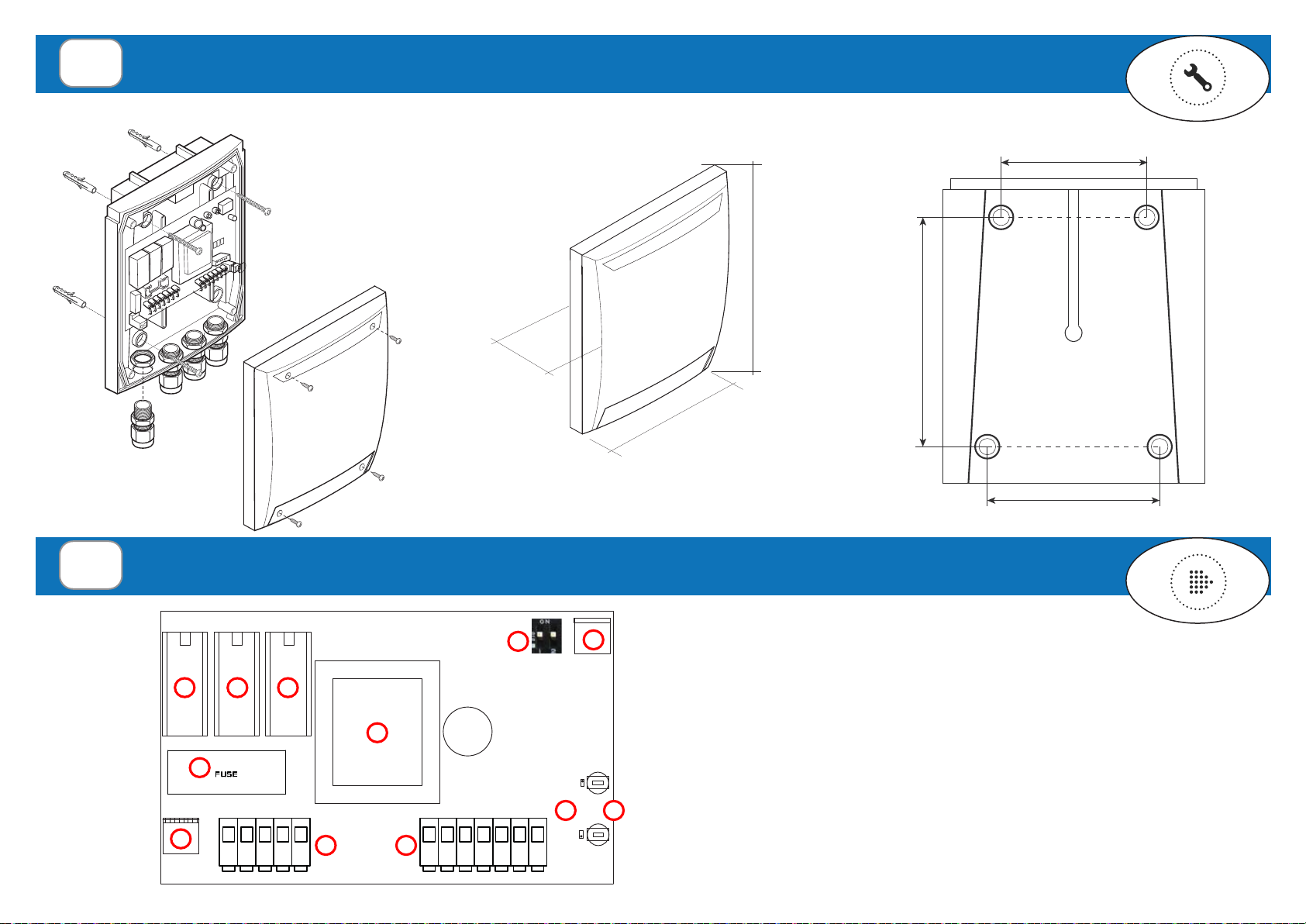
2.1 Mounting the product
2.2 Control Unit diagram
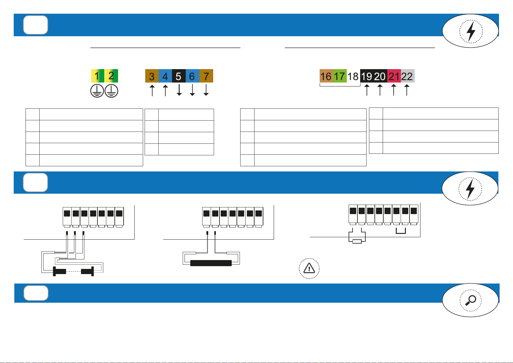
2.3 Electrical connections
2.4 Wired safety device connections
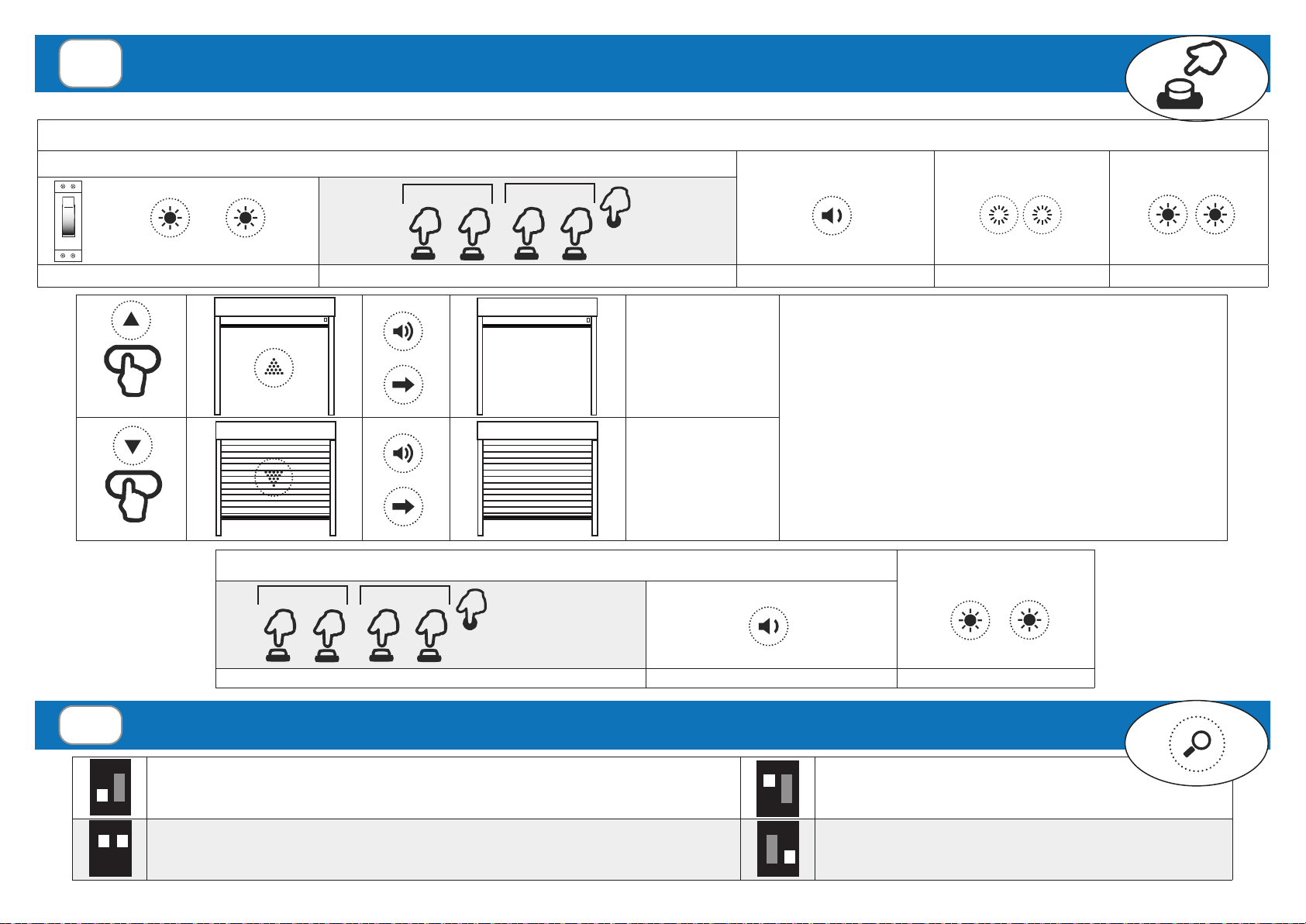
3. Preliminary check and initial start-up-----------pages 6 - 8
3.1 Limit switch configuration and direction check
3.2 Functioning mode
3.3 Exclusion of the safety edge
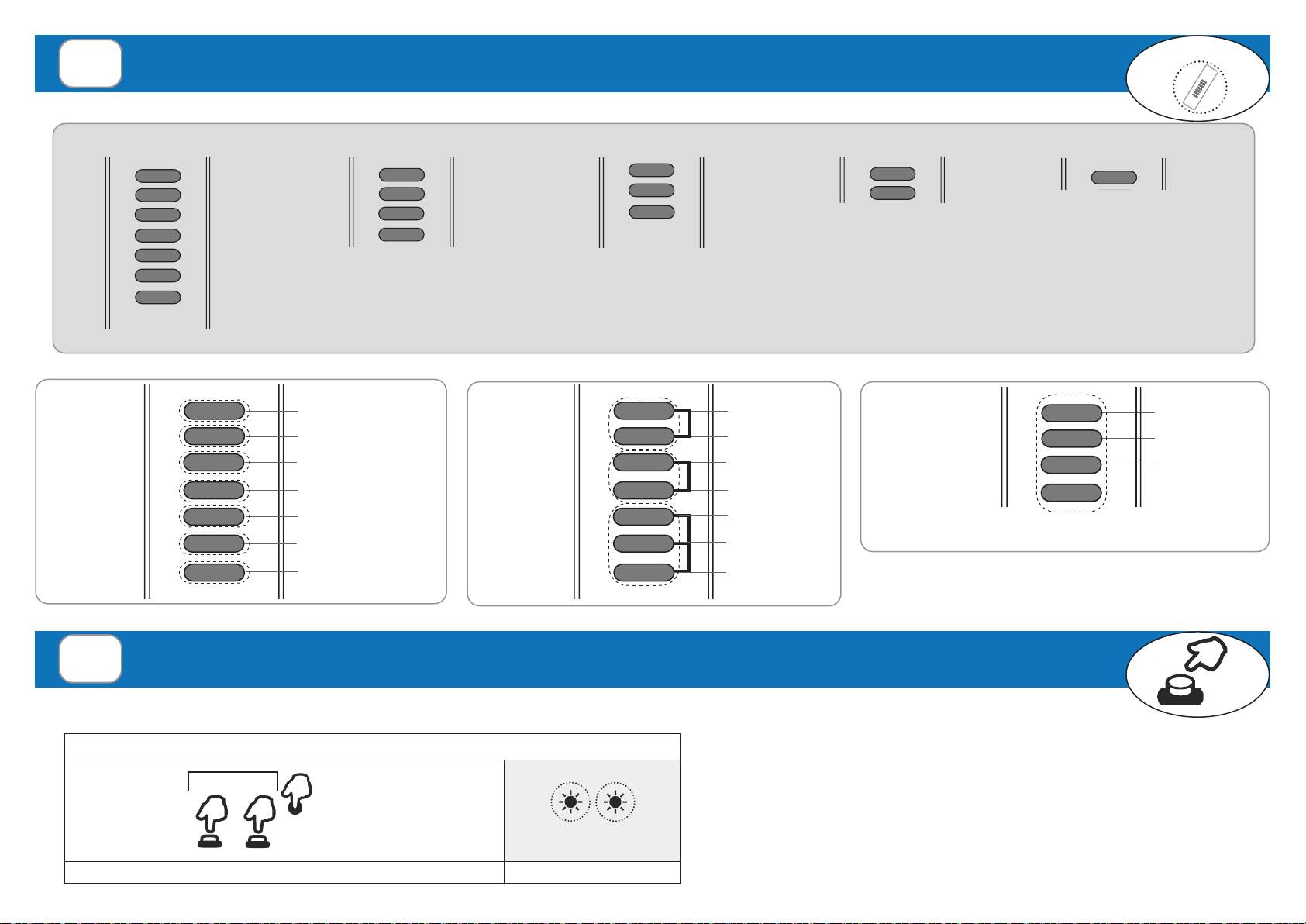
4. Transmitters & memorization---------------------pages 9 - 11
4.1 Memorization programming mode
4.2 Radio codes memorization
4.3 Single channel: door status request (ask)
4.4 Remote memorization of the first transmitter
4.5 Remote memorization of further transmitters
5. Transmitters deletion-----------------------pages 12 - 13
5.1 Remote deletion of a transmitter
6. Time setting----------------------------------page 13
6.1 Auto close time setting
7. Reset ------------------------------------------page 14
7.1 Control unit reset
8. Technical specification---------------------page 14
9. Troubleshooting------------------------------page 15
The above mentioned product must be installed only by qualified technical personnel in compliance with the standards of automatic openings. All connections must
be rated for a single-phase power supply of 240Vac. For the disconnection from the power line, use an all-pole switch with contact with an opening of at least 3.5
mm. Only suitable materials for the connections must be used to guarantee insulation that complies with current standards on the subject of electrical safety. All the
necessary safety devices are to be seen separately. Incorrect wiring will cause incorrect functioning impairing the safety purpose for which the product has been
designed so that people injuries could occur; failure to follow instructions can cause personal injury and/or property damage. The correct functioning of the product
must be checked once a year. Keep the 240Vac wires separately from the low voltage safety wires. The earth-wires must be fixed with an additional fastening on
the terminals; this fastening has to be done by qualified technical personnel during the installation phase. The appliance has been tested with a power supply wire
type H05VV-F; the power supply wires for outdoor use have not to be lighter than the ordinary wires type H05RN-F. The safety devices have to be in conformity with
EN12978. The installation of the control unit has to be done by fixing the box vertically with the cable glands downwards. The product is in conformity with the RAEE
and RoHS directive.
The earth wire must be longer than the other wires because it must be the last to break off if the cable clamps are slack. Remember that there are specific standards
that must be complied with both as regarding the safety of the electrical systems and as regarding the remote control of tubular motors for roller blind.
In the view of a constant development of their products, the manufacturer reserves the right for changing technical data and features without prior notice.
The connection between the control unit and the auxiliary device must be done using double insulated cables. The auxiliary device connected must be a Class II device.
In case of an external aerial is connected the connections must be done using double insuleted cables.
WARNINGS