Bircher Reglomat RFGate 2.2.A User manual

Safety instructions
1
Transmitter Receiver
ON
12
2032
2032
+
+
Transmitter
PCB Transmitter
Terminals
Battery 1 CR2032
Battery 2 CR2032
LED (activation)
DIP - Switch
Push button
Antenna
Receiver
Receiver printed circuit board
Terminals
LED 1 (system readiness,
channel ➔Sender 1)
LED 2 (system readiness,
channel ➔Sender 2)
Key
DIP switch
LED 3 (programming mode)
Buzzer
Antenna
12
1
0
10
arning: Switch off the operating voltage before working on the system. Only trained, qualified personnel may perform installation and startup.
The unit may only be opened and repaired by Bircher Reglomat employees. The switching unit may only be used to protect against dangers at crushing
and automatic industrial doors (designated use). Applicable regulations on industrial door safety must be complied with. Always consider the safety
functions of your application as a whole, never just in relation to one individual section of the system. The installer is responsible for carrying out a
risk assessment and installing the industrial door system correctly. Notice: It’s recommended to change the battery every year.
Startup
2
Installing the transmitter (cable outlet at bottom)
2.1
Recommendedstart-upsequence:Mountingsensor/Initialisation/Connectsensor
Notice:
For technical reasons relating to radio trans-
mission, the transmitter and receiver should
not be installed on the same surface if possi-
ble.
The distance between transmitter and receiver
as well as between the transmitters among
themselves has to be at least 1m.
Tip:
If the distance between the transmitter and
receiver is relatively large, we recommend
programming the transmitters on the receiver
before installation.Transmitters can be learned
in with or without a connected detector /
switch.
175 mm
Transmitter: insert batteries
2.2
1. Remove the PCB from the housing.
2. Insert the enclosed batteries (type CR2032).
Important:
Insert battery 1first and then battery 2.
Unless this order is observed, correct function
is not guaranteed.
Installing the receiver (cable outlet at bottom)
2.3
Cable diameter:
3 – 6.5 mm
Connecting the receiver
2.4
1See 3.1 See 3.1
1: Wire up the power supply to the controller 2: Wire up the output to the controller
Note correct polarity for DC! Input type
sensor/safety edge
Input type
Contact NC
Input type
Contact NO
The system is not
fused.We recommend
protecting the supply
with a fuse of min.
100 mA, max. 250 mA.
Controller Input
Sensor 8.2 kOhm
Input
NC
Input
NO
see 3.3
Drilling template
2 2
ON
12
2032
2032
+
+
1
2
RFGate 2.2.A
Trans ation of the origina instructions
Quality
international
level
EN ISO
9001
Radio transmission system
for safety edges
ENGLISH
308077A
02/13
Genera
162 mm

Initialisation2.5
Programming a transmitter to output 1
2.5.1
Notice:
The distance between the transmitter and receiver must be at least 1 m.
Up to 7 transmitters can be programmed for each output. Transmitters can be learned in with or without a connected detector / switch.For reasons of
safety, memory mode is exited automatically 10 seconds after the last key press.
Enter the memory function.
1. Press the key of the receiver until a signal sounds.
LED3 lights up red for maximum 10 seconds (display memory readiness output 1).
The transmitter must be activated within these 10 seconds:
2. Press the key of the transmitter until a signal sounds on the receiver.
Other transmitters can now also be programmed by pressing their keys
Programming a transmitter to output 2
2.5.2
Enter the memory function.
1. Press the key of the receiver until a signal sounds. LED3 lights up red.
2. Press the key again until a signal sounds.
LED3 flashes red for maximum 10 seconds. (Display memory readiness output 2).
The transmitter must be activated within these 10 seconds:
3. Press the key of the transmitter until a signal sounds on the receiver.
Other transmitters can now also be programmed by pressing their keys.
Finishing programming: Wait 10 seconds until two signals sound.
Tip:
The transmitters for output 1 and the transmitters for output 2 can also be learned in without an interruption. After step 2.5.1 (programming the
transmitters for output 1, LED3 is permanently lit), the key of the receiver must be pressed within 10 seconds until a signal sounds. This means the
memory function goes directly to step 2.5.2 (LED3 flashes). Now the transmitters for output 2 can be learned by pressing the key (transmitter).
Reset: Delete transmitter memory
2.5.3
Enter the memory function
1. Press the key of the receiver until a long signal sounds. Signal sequence:
The transmitter memory is now deleted. After 10 seconds, two signals sound and memory mode is exited automatically.
Connecting the detector2.6
ire up the transmitter with a safety edge 8.2 kohm ire up the transmitter with contact (e.g. wicket door)
RF ate 2.1.S / 2.1.S.NC RF ate 2.1.2.F with NO contact, RF ate 2.1.S with NO contact, RF ate 2.1.S.F with NC contact, onlyRF ate2.1.S.NC
Function test2.7
Connect the system to power. Press all safety edges one after another and check the behaviour of the receiver and/or controller is as required.
Cable diameter:
RF ate 2.1.S / RF ate 2.1.S.NC: 3 … 6,5mm;
RF ate 2.1.S.F: 3.5 … 5 mm

Extended configurations, factory settings
3
Operation with testing (cat. 2 acc. to EN ISO 13849-1)3.1
DIP switch setting:
Test NO contact (test activated = contact closed) Test NC contact (test activated = contact open)
Factory settings
Connection possibilities:
On controller: contact PNP- or NPN-transistor
Applications with limit switch (bridges the safety edge!)3.2
ire up transmitter to limit switch
RF ate 2.1.S RF ate 2.1.S.F
Output NO instead of 8.2 kohm resistor3.3
On both relay outputs, the 8.2 kohm resistor can be disconnected if required by removing a jumper.
with Jumper: without Jumper: Jumper output 1: Jumper output 2:
Overview tables for DIP switches3.4
Receiver: Transmitter:
1133224455
ONON
1 ON Default setting
5511332244
ONON
1 OFF No safety operation!
5522331144
ONON
2 ON 869.85 MHz
5522331144
ONON
2 OFF 868.95 MHz
55
33
112244
ONON
3 ON Test input NC
55
33
112244
ONON
3 OFF Test input NO
55
44
112233
ONON
4 ON Frequency adaptation on
55
44
112233
ONON
4 OFF Frequency adaptation off
11223355
44
ONON
5 ON Default setting
4455
112233
ONON
5 OFF No function!
11
2
2
ONON
1 ON Safety edge
with 8.2 kOhm
11
22
ONON
1 OFF Contact NO (s. 2.6)
22
11
ONON
2 ON 869.85 MHz
22
11
ONON
2 OFF 868.95 MHz
Factory settings3.5
For safety operation
Receiver: Transmitter:
Important:
Receiver switches 1 and 5 always in ON position.Correct
operation is not guaranteed if OFF!
Factory settings

Disp aying / Troub e shooting
4
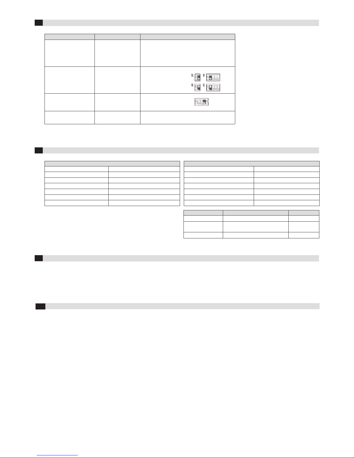
Event / display Reason Solution
Memorise on transmitter:
Signal sounds for 10 seconds
Transmitter memory full.
The maximum number of
7 transmitters per output
has been exceeded
Delete memory
Memorise on transmitter:
No signal after transmitter
key press
No radio connection.
Frequencies of transmitter
and receiver must match
Set DIP switch correctly:
Frequency 1 (869.85 MHz)
or
Frequency 2 (868.95 MHz)
(Factory setting)
In operation:
Malfunctions (e.g. close
to a construction crane)
Highly disrupted radio
connection
Switch on automatic
frequency adaptation
On every actuation:
Signal sounds 2-4 times Batteries soon depleted Change batteries
Technica data
5
System (RF ate 2.2.A)
Frequency bands 868.95 MHz & 869.85 Mhz
Range 25 m, under optimum conditions up to 75 m
Protection class (IEC 60529) IP 55
Pollution degree 2
Ball pressure test (IEC 695-10-2) PCB: 125°; housing: 75°
Software Class A
Working temperature -20°C to +55°C
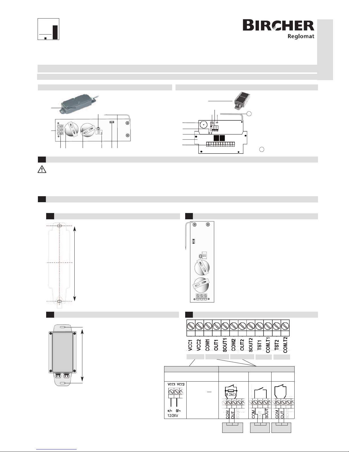
Receiver (RF ate 2.2.R.A)
Transmitter memory
7+7
Output Relay
, 24 V, 0,5 A;
micro disconnection
1B
Supply voltage
12 / 24 VACDC
Power consumption
0.5 W @ 12 V, 1.2 W @ 24 V
Rated surge voltage (acc. to EN 60730-1) 300 V
Test signal input 12 / 24 VACDC
Dimensions 178 x 80 x 45 mm
Transmitter (RF ate 2.1.S, RF ate 2.1.S.NC) (RF ate 2.1.S.F)
Supply voltage 3 VDC (2 x Lithium CR2032)
Power consumption When transmitting: 17 mA
In sleep mode: 16 µA
Dimensions 190 x 51 x 36 mm 190 x 51 x 22 mm
Dec aration of conformity
6
Bircher Reg omat AG, Wiesengasse 20, CH-8222 Beringen, Switzer and, www.bircher-reg omat.com
7Contact data
Manufacturer: Bircher Reglomat A , Wiesengasse 20, CH-8222 Beringen, Employee responsible for docu.: Bircher Reglomat A , Wiesengasse 20, CH-8222 Beringen
Product: Switching device with radio transmission system, Models: RF ate 2.1, RF ate 2.2, Serial numbers: WWYY000000 - WWYY999999, Notified Body: Suva certificate
authority, division: technics, EU-ID-number 1246, EC-type-examination certificates: E 6945, Following directives have been observed: Machinery directive 2006/42/E ,
R&TTE Directive 1999/5/E , Following standards have been taken into account: EN ISO 13849-1, EN 12978,
Signee: CTO, Dr. M. Loschonsky / COO, D. Nef, CH-8222 Beringen
Other Bircher Reglomat Microphone System manuals