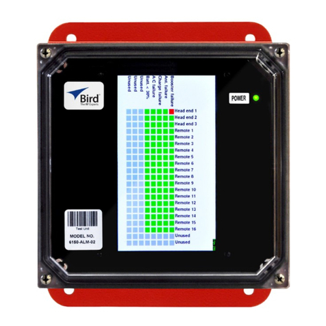
BIRD 6150-ALM-03 User manual

6150-ALM-03
Operation Manual
©
Copyright 2020
by Bird Technologies Inc.
Instruction Book Part Number 920-6150-ALM-03 Rev. P1
A

i
Safety Precautions
The following are general safety precautions that are not necessarily related to
any specific part or procedure, and do not necessarily appear elsewhere in this
publication. These precautions must be thoroughly understood and apply to all
phases of operation and maintenance.
WARNING
Keep Away From Live Circuits
Operating Personnel must at all times observe general safety
precautions. Do not replace components or make adjustments to
the inside of the test equipment with the high voltage supply
turned on. To avoid casualties, always remove power.
WARNING
Do Not Service Or Adjust Alone
Under no circumstances should any person reach into an enclosure
for the purpose of service or adjustment of equipment except in the
presence of someone who is capable of rendering aid.
WARNING
Safety Earth Ground
An uninterruptible earth safety ground must be supplied from the
main power source to test instruments. Grounding one conductor of
a two conductor power cable is not sufficient protection. Serious
injury or death can occur if this grounding is not properly supplied.
WARNING
Resuscitation
Personnel working with or near high voltages should be familiar with
modern methods of resuscitation.
WARNING
Remove Power
Observe general safety precautions. Do not open the instrument
with the power applied.

Safety Precautions
ii
Safety Symbols
Note: Calls attention to supplemental information.
Safety Statements
USAGE
ANY USE OF THIS INSTRUMENT IN A MANNER NOT SPECIFIED BY
THE MANUFACTURER MAY IMPAIR THE INSTRUMENT’S SAFETY
PROTECTION.
USO
EL USO DE ESTE INSTRUMENTO DE MANERA NO ESPECIFICADA
POR EL FABRICANTE, PUEDE ANULAR LA PROTECCIÓN DE
SEGURIDAD DEL INSTRUMENTO.
BENUTZUNG
WIRD DAS GERÄT AUF ANDERE WEISE VERWENDET ALS VOM
HERSTELLER BESCHRIEBEN, KANN DIE GERÄTESICHERHEIT
BEEINTRÄCHTIGT WERDEN.
UTILISATION
TOUTE UTILISATION DE CET INSTRUMENT QUI N’EST PAS
EXPLICITEMENT PRÉVUE PAR LE FABRICANT PEUT
ENDOMMAGER LE DISPOSITIF DE PROTECTION DE
L’INSTRUMENT.
IMPIEGO
QUALORA QUESTO STRUMENTO VENISSE UTILIZZATO IN MODO
DIVERSO DA COME SPECIFICATO DAL PRODUTTORE LA
PROZIONE DI SICUREZZA POTREBBE VENIRNE COMPROMESSA.
WARNING
Warning notes call attention to a procedure, which if not correctly
performed, could result in personal injury.
CAUTION
Caution notes call attention to a procedure, which if not correctly
performed, could result in damage to the instrument.

NFPA Alarm Panel 6150-ALM-03
iii
SERVICE
SERVICING INSTRUCTIONS ARE FOR USE BY SERVICE - TRAINED
PERSONNEL ONLY. TO AVOID DANGEROUS ELECTRIC SHOCK, DO
NOT PERFORM ANY SERVICING UNLESS QUALIFIED TO DO SO.
SERVICIO
LAS INSTRUCCIONES DE SERVICIO SON PARA USO EXCLUSIVO
DEL PERSONAL DE SERVICIO CAPACITADO. PARA EVITAR EL
PELIGRO DE DESCARGAS ELÉCTRICAS, NO REALICE NINGÚN
SERVICIO A MENOS QUE ESTÉ CAPACITADO PARA HACERIO.
WARTUNG
ANWEISUNGEN FÜR DIE WARTUNG DES GERÄTES GELTEN NUR
FÜR GESCHULTES FACHPERSONAL.
ZUR VERMEIDUNG GEFÄHRLICHE, ELEKTRISCHE SCHOCKS, SIND
WARTUNGSARBEITEN AUSSCHLIEßLICH VON QUALIFIZIERTEM
SERVICEPERSONAL DURCHZUFÜHREN.
ENTRENTIEN
L’EMPLOI DES INSTRUCTIONS D’ENTRETIEN DOIT ÊTRE RÉSERVÉ
AU PERSONNEL FORMÉ AUX OPÉRATIONS D’ENTRETIEN. POUR
PRÉVENIR UN CHOC ÉLECTRIQUE DANGEREUX, NE PAS
EFFECTUER D’ENTRETIEN SI L’ON N’A PAS ÉTÉ QUALIFIÉ POUR
CE FAIRE.
ASSISTENZA TECNICA
LE ISTRUZIONI RELATIVE ALL’ASSISTENZA SONO PREVISTE
ESCLUSIVAMENTE PER IL PERSONALE OPPORTUNAMENTE
ADDESTRATO. PER EVITARE PERICOLOSE SCOSSE ELETTRICHE
NON EFFETTUARRE ALCUNA RIPARAZIONE A MENO CHE
QUALIFICATI A FARLA.

About This Manual
iv
About This Manual
This manual covers the installation, operating & maintenance instructions for:
Changes to this Manual
We have made every effort to ensure this manual is accurate. If you discover any
errors, or if you have suggestions for improving this manual, please send your
comments to our Solon, Ohio factory. This manual may be periodically updated.
When inquiring about updates to this manual refer to the part number and
revision on the title page.
6150-ALM-03

v
Table of Contents
Safety Precautions . . . . . . . . . . . . . . . . . . . . . . . . . . . . . . . . . . . . . . . . . i
Safety Symbols . . . . . . . . . . . . . . . . . . . . . . . . . . . . . . . . . . . . . . . . . . . . . . . . . . ii
Safety Statements . . . . . . . . . . . . . . . . . . . . . . . . . . . . . . . . . . . . . . . . . . . . . . . ii
About This Manual . . . . . . . . . . . . . . . . . . . . . . . . . . . . . . . . . . . . . . . . iv
Changes to this Manual . . . . . . . . . . . . . . . . . . . . . . . . . . . . . . . . . . . . . . . . . . . iv
Chapter 1 Introduction . . . . . . . . . . . . . . . . . . . . . . . . . . . . . . . . . . . . . 1
Monitored Alarms . . . . . . . . . . . . . . . . . . . . . . . . . . . . . . . . . . . . . . . . . . . . . . . 1
Other Monitored Parameters . . . . . . . . . . . . . . . . . . . . . . . . . . . . . . . . . . . . . . 1
Alarm Reporting . . . . . . . . . . . . . . . . . . . . . . . . . . . . . . . . . . . . . . . . . . . . . . . . . 2
Cable Connections . . . . . . . . . . . . . . . . . . . . . . . . . . . . . . . . . . . . . . . . . . . . . . . 3
Chapter 2 Installation . . . . . . . . . . . . . . . . . . . . . . . . . . . . . . . . . . . . . . 4
Installing the Alarm Panel . . . . . . . . . . . . . . . . . . . . . . . . . . . . . . . . . . . . . . . . . 4
Booster - Alarm Panel Connection . . . . . . . . . . . . . . . . . . . . . . . . . . . . . . . 5
Alarm Panel Output Connection . . . . . . . . . . . . . . . . . . . . . . . . . . . . . . . . 5
Chapter 3 Operation . . . . . . . . . . . . . . . . . . . . . . . . . . . . . . . . . . . . . . . 7
Normal Operation . . . . . . . . . . . . . . . . . . . . . . . . . . . . . . . . . . . . . . . . . . . . . . . 7
Alarm Condition . . . . . . . . . . . . . . . . . . . . . . . . . . . . . . . . . . . . . . . . . . . . . . 7
Audible Alarm Test . . . . . . . . . . . . . . . . . . . . . . . . . . . . . . . . . . . . . . . . . . . 7
Chapter 4 Specifications. . . . . . . . . . . . . . . . . . . . . . . . . . . . . . . . . . . . 8
Limited Warranty . . . . . . . . . . . . . . . . . . . . . . . . . . . . . . . . . . . . . . . . . . 9

1
Chapter 1 Introduction
The Bird NFPA Alarm Panel is a signal booster alarm status annunciator that
provides a convenient means of monitoring your signal booster alarms from a
reasonably nearby location such as a security desk or main lobby desk located in
the same building as the signal booster.
Monitored Alarms
The alarm panel is capable of monitoring the five alarms required for NFPA
compliance including:
Signal Booster Failure — This is a summed alarm that is active when any
number of fault conditions arise within the booster unit such as when an over
current or high temperature event occurs.
Loss of AC Power — Indicates that AC power to the booster unit has failed.
Antenna Malfunction — Indicates there is a loss of RF cable integrity
between the signal booster unit and the remote antenna line sensor. In order to
detect an antenna malfunction an antenna line sensor must be installed as close
to the Donor antenna as possible. This sensor works with the Bias-T assembly
inside the booster cabinet to verify the continuity of the antenna line
Low Battery Condition — The source of this alarm is the battery backup unit
and it indicates that the battery backup voltage level has dropped significantly.
Charger Failure — The source of this alarm is the battery backup unit and it
indicates failure of the battery charger. If the battery charger looses AC power
this alarm will be active.
Other Monitored Parameters
In addition to the NFPA alarms, the Alarm Panel displays the status following
parameters:
Power — when illuminated indicates the alarm panel is connected to/and
receiving power from a signal booster.
Link Status — Link status indicates the status of the alarm panel’s connection
to the signal booster.
Note: The two spare indicators are provided for future
capabilities and do not currently provide active alarm indications.

NFPA Alarm Panel 6150-ALM-03
2
Figure 1 Alarm Panel
63$5(
63$5(
&+$5*()$,/
/2:%$77(5<
$170$/)81&7,21
/2662)$&32:(5
6,*1$/%2267(5)$,/85(
/,1.67$786
32:(5
$ODUP1RWL¿FDWLRQ
%X]]HU
%X]]HU5HVHW7HVW
3XVKEXWWRQ
$ODUP2XWSXW
7HUPLQDOV
$ODUP/('
,QGLFDWRUV
12 12
12
12
12 12
12
12
1& 1&
1&
1&
1& 1&
1&
1&
&20 &20
&20
&20
&20 &20
&20
&20
/2662)
$&32:(5
6%)$,/
&+$5*(
)$,/
$17(11$
0$/)81&7,21
63$5(
63$5(
63$5(
/2:%$7
32:(52.
/,1.
67$786
6,*1$/
%2267(5
)$,/85(
/2662)
$&32:(5
$17(11$
0$/)81&7,21
/2:
%$77(5<
&+$5*(
)$,/
63$5(
63$5(
'2127581:,5(629(5/('¶6
$/$50
7(675(6(7
&RYHU&ORVHG &RYHU2SHQ
Alarm Reporting
When an Alarm condition is detected the appropriate LED will change to RED
and an audible alarm will sound. A pushbutton is provided inside the alarm
panel enclosure to silence the audible alarm.

Introduction
3
Cable Connections
Signal Booster — The Alarm Panel connects to the signal booster using a
standard Ethernet cable with RJ-45 connectors. The Ethernet cable provides
operating voltage for the Alarm Panel and carries the booster status.
Facility Panel — Optionally, the NPFA alarm status may be extended from the
Alarm Panel to an existing facility alarm panel.
Figure 2 Alarm Panel Connections
63$5(
63$5(
&+$5*()$,/
/2:%$77(5<
$170$/)81&7,21
/2662)$&32:(5
6,*1$/%2267(5)$,/85(
/,1.67$786
32:(5
6LJQDO%RRVWHU
$ODUP3DQHO
)DFLOLW\
$ODUP3DQHO
6WDQGDUG
(WKHUQHW&DEOH
7ZLVWHG3DLU
&DEOH

4
Chapter 2 Installation
Installing the Alarm Panel
The alarm panel is designed to be wall mounted and has a built-in mounting
flange on the top and bottom of the enclosure. Each flange has two screw holes
and all four holes should be used during installation to insure the box is fastened
firmly.
Place the panel in a convenient viewable location. The Alarm panel has an
audible buzzer but should be placed where the LED indicators can be easily
seen.
Figure 3
shows the mechanical mounting details of the alarm panel
enclosure.
Figure 3 Alarm Panel Mounting
63$5(
63$5(
&+$5*()$,/
/2:%$77(5<
$170$/)81&7,21
/2662)$&32:(5
6,*1$/%2267(5)$,/85(
/,1.67$786
32:(5
0RXQWLQJ
%UDFNHWV

Installation
5
Booster - Alarm Panel Connection
The Alarm Panel is equipped with one RJ-45 Alarm input connector. T h is
connector is used to connect a Bird signal booster to the alarm panel. The RJ-45
connector is used for alarm panel power and alarm data. See
Figure 4
.
Bird Boosters with an RJ-45 Alarm Panel output can connect directly to the RJ-45
connector on the bottom of the alarm panel. A standard Ethernet cable is used
for the connection, the maximum length for this cable is 300 feet (100 meters).
The RJ-45 connection supplies power for the alarm panel and interfaces the
boosters NFPA alarms.
Boosters that do not have Bird’s RJ-45 Alarm Panel output can only connect to
the alarm panel by using Bird’s alarm panel adapter board (7120A420).
Figure 4 Alarm Input connections
$ODUP,QSXW&RQQHFWRU
5-IURPERRVWHU
$ODUP2XWSXW
RXWSXWWRFXVWRPHUDODUPSDQHO
FRQGXLW
Alarm Panel Output Connection
Alarm output terminals are provided to allow the NFPA alarms to be extended to
a facility alarm panel. See
Figure 5 on page 6
.
The terminal connectors in the alarm panel can accommodate wire gauge
between 18 and 26. For ease of installation it is recommended that CAT 6 STP
(shielded twisted pair) or even CAT 7 cable be used to carry the alarm
information from the alarm panel to the facility alarm panel.
One of the important considerations when installing the twisted pairs for signal
lines is noise on the lines which may cause false alarm indications at the alarm
panel. Using good quality cable with sufficient shielding is important. When
laying the cable run avoid running it next to the building’s AC wiring or near
strong noise sources like motors.
If your installation requires the distance between the alarm panels to be greater
than several thousand feet consult with the factory before running the signal
cable. The wire gauge and shielding used for the signal lines will determine the
workable distance, thicker wire gives greater distance but can be cost
prohibitive.
Inside the alarm panel enclosure the twisted pairs must be connected to the
appropriate terminals connectors as shown in
Figure 5
. Each of the connection
points for the five NFPA alarm signals are identified.

NFPA Alarm Panel 6150-ALM-03
6
Note: The three spare connectors are provided for future
capabilities and do not currently provide active alarm indications.
The alarm terminals can be connected as normally open or normally closed
circuits. Normally closed is defined as a contact pair that is normally closed
when the booster is powered-up, operating normally, with no alarm conditions.
Bring the twisted pairs into the alarm panel box through the conduit opening at
the bottom of the box.
Figure 5 Alarm Output Terminals
To complete the installation of the alarm panel make sure the wire connections
inside the box do not pinch when the door is closed. Close the door and tighten
the screws in the front panel clamps.

7
Chapter 3 Operation
Normal Operation
When the Alarm Panel is connected to a signal booster and the signal booster is
powered up, the alarm panel will display Power (green) link status (green) with
the signal booster and the alarm status of the signal booster.
When the alarm panel is powered-up and the signal booster is operating
normally (no faults) the status lights will be green for the monitored NFPA alarm
parameters.
Alarm Condition
When the signal booster detects a malfunction for one of the monitored NFPA
parameters, the associated indicator will change to red and the audible alarm
will sound.
Silencing Alarms
To silence the alarm, loosen clamps securing the front cover of the Alarm Panel,
open the front cover and press the reset button at the top of the alarm panels
circuit board.
Note: The reset button will silence active alarms for 24 hours,
after 24 hours, if the alarm is still active the audible alarm will
sound again.
Audible Alarm Test
Note: A test of the audible alarm may only be done when there
are no active alarms.
To test the audible alarm, loosen clamps securing the front cover of the Alarm
Panel, open the front cover and press the reset/test button at the top of the
alarm panels circuit board.

8
Chapter 4 Specifications
Specification Value
Alarms Monitored
Signal Booster Failure,
Loss of AC Power,
Antenna Malfunction,
Low Battery Condition,
Charger Failure.
Alarm Indications
LED
Buzzer
Red
72 dB
Alarm Input
Alarm Input Ethernet
Alarm Input Connector RJ-45
Alarm Output
Alarm Output Connector Spring Clamp
Alarm Types Normally Open,
Normally Closed
Max Allowable Voltage 30 VDC
Max Current 1 A
Wire Size 18 to 26 AWG
Enclosure Rating NEMA 4
IP 65
Operating Temperature 32 °F to 122 °F (0 °C to 50 °C)
Enclosure Dimensions
8” x 6” x 3.5”
(20.32 cm x 15.24 cm x 8.89 cm)
H x W x D
Enclosure Weight 7 lbs (3.18 kg)

6
Limited Warranty
All products manufactured by Seller are warranted to be free from defects in
material and workmanship for a period of one (1) year, unless otherwise
specified, from date of shipment and to conform to applicable specifications,
drawings, blueprints and/or samples. Seller’s sole obligation under these
warranties shall be to issue credit, repair or replace any item or part thereof
which is proved to be other than as warranted; no allowance shall be made for
any labor charges of Buyer for replacement of parts, adjustment or repairs, or
any other work, unless such charges are authorized in advance by Seller.
If Seller’s products are claimed to be defective in material or workmanship or
not to conform to specifications, drawings, blueprints and/or samples, Seller
shall, upon prompt notice thereof, either examine the products where they are
located or issue shipping instructions for return to Seller (transportation-charges
prepaid by Buyer). In the event any of our products are proved to be other than
as warranted, transportation costs (cheapest way) to and from Seller’s plant, will
be borne by Seller and reimbursement or credit will be made for amounts so
expended by Buyer. Every such claim for breach of these warranties shall be
deemed to be waived by Buyer unless made in writing within ten (10) days from
the date of discovery of the defect.
The above warranties shall not extend to any products or parts thereof which
have been subjected to any misuse or neglect, damaged by accident, rendered
defective by reason of improper installation or by the performance of repairs or
alterations outside of our plant, and shall not apply to any goods or parts
thereof furnished by Buyer or acquired from others at Buyer’s request and/or to
Buyer’s specifications. Routine (regularly required) calibration is not covered
under this limited warranty. In addition, Seller’s warranties do not extend to the
failure of tubes, transistors, fuses and batteries, or to other equipment and parts
manufactured by others except to the extent of the original manufacturer’s
warranty to Seller.
The obligations under the foregoing warranties are limited to the precise terms
thereof. These warranties provide exclusive remedies, expressly in lieu of all other
remedies including claims for special or consequential damages. SELLER NEITHER
MAKES NOR ASSUMES ANY OTHER WARRANTY WHATSOEVER, WHETHER EXPRESS,
STATUTORY, OR IMPLIED, INCLUDING WARRANTIES OF MERCHANTABILITY AND
FITNESS, AND NO PERSON IS AUTHORIZED TO ASSUME FOR SELLER ANY
OBLIGATION OR LIABILITY NOT STRICTLY IN ACCORDANCE WITH THE FOREGOING.

Table of contents
Other BIRD Security System manuals