Bison BA79K User manual

1
————— Instruction Manual —————
MODEL BA79K
Adjustable Playground Pole System
P A R T S L I S T
Item Qty Description Item Qty Description
A 1 H-Frame **L 1 5/8’ x 8” Hex Bolt / 5/8” x 9” Hex Bolt
B 1 Extension Arm M 2 5/8” Lock Nut
C 1 I-Rod N 2 5/8” x 6 1/2” Hex Bolt
D 1 “J” Bolt template O 1 1/2” x 4” Hex Bolt
E 1 Vertical Pole P 4 1/2” Lock Nut
F 1 Hand Crank Q 3 1/2” x 5” Hex Bolt
G 4 “J” Bolt R 1 Spring Assist
H 4 36” Rebar S 1 Height Indicator Label
I 12 5/8” Hex Nut *T 1 1/2”-13 x 2” Hex Bolt / 1/2” Lock Nut
J 8 5/8” Flat Washer U 4 Safety Cap
Note: * refers to factory installed hardware; ** refers to hardware included with H-Frame
K 4 5/8” Lock Washer
Warning!
Do Not Mount Pole to Existing Concrete Surfaces!
♦ Inspect all contents prior to installation. Report any missing parts to dealer immediately.
♦ Read all instructions before proceeding.
Warning!
Young players are at risk when they slam dunk on popular lowered height basketball systems.
See your dealer for information on Safety Nets.
Date: 02/10/10 Rev: 8 B.A. N.J.C. File: BA79k.mp; 79kinst.dwg Ref#: 920192
Customer Service
(800) 247-7668
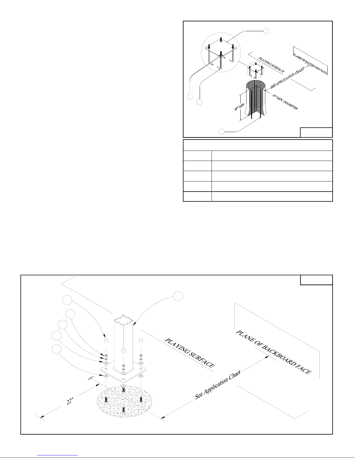
1. Select the location for the concrete base footing using the Application chart to maximize hard playing
surface under and around the goal while minimizing interference with driveway traffic when unit is
adjusted at the lowest position. See Figure A.
2. Dig a minimum 20" diameter hole 48" deep. Be sure to bell out the bottom 12" of the hole at least an
additional 4" in diameter. A larger diameter hole will always be better than one not big enough.
See Figure A.
Note:
Center of template/concrete foundation should be a minimum of 22" from any wall, fence, etc. to avoid
interference with adjusting crank on the back side of the pole.
2
3. Thread a 5/8" Hex Nut (I) on to each "J" Bolt (G)
leaving at least 2 1/2" of threads exposed above the
5/8” Hex Nuts (I) Place each "J" Bolt (G) through
the holes in the "J" Bolt Template (D) and thread a
second 5/8" Hex Nut (I) onto each "J" Bolt (G) and
tighten. Make sure that a minimum 2" of thread is
exposed and the legs of the "J" bolts (G) are
pointing toward each other. See Figure A.
4. Make sure that you have the following tools
available prior to pouring the concrete footing: a
level, a broomstick or similar pole to vibrate
concrete, and a tape measure to assure that the "J"
bolt assembly is embedded in the concrete square
to the desired position of the backboard. The 20"
diameter by 48" deep hole will require
approximately 1/2 cu. yard of 3000 psi concrete
(22 to 24 60# bags of premix concrete). Please
adjust the amount if hole is deeper and/or wider.
Having enough concrete before you start will
ensure proper strength of the footing. See Figure A
5. Drive Rebar (H) into bottom of the hole equally
spaced to form a square. Mix the concrete according to instructions on the bag. It is advantageous to
have the mixture be "wet". This will increase your working time and allow batches to mix in the hole.
Pour the hole full to ground level. Insert the broomstick into the wet concrete and agitate up and down.
REPEAT SEVERAL TIMES. Insert the "J" Bolt Assembly (D, G, I) into wet concrete. Vibrate assembly
as you insert it so the concrete fills in around the "J" bolts (G). Be sure the "J” Bolt Template (D) is
pressed firmly against the surface of the wet concrete and centered on the concrete foundation. The bolt
pattern must be parallel with the desired position of the backboard and edge of playing surface.
See Figure A and B.
Rim Height Distance from Backboard Face to Center of Foundation
7’6” 69 1/2”
8’ 67 1/2”
9’ 63 1/2”
10’ 55 1/2”
Application Chart
D
H
IG
FIGURE A
U
K
J
J
I
E
FIGURE B

3
6. Clean excess concrete from edge of hole and level the concrete from the edge of the "J” Bolt
Template (D). Clean excess concrete from both threads and nuts. Double check the position and
levelness of "J" Bolt Template (D). Allow footing to cure for seven (7) days.
7. Remove the upper 5/8" Hex Nuts (I) from the "J" Bolts (G) and remove and discard the “J” Bolt
Template (D). Thread the 5/8" Hex Nuts (I) back onto the "J" Bolts (G)and finger tighten against the
5/8” Hex Nuts (I) embedded in the concrete. See Figure B.
8. Place 5/8" Flat Washers (J) onto the exposed bolts. Now place the Vertical Pole (E) onto the exposed
bolts being careful not to damage the threads. Next place 5/8" Flat Washers (J), 5/8" Lock Washers
(K) and 5/8" Hex Nuts (I) onto the exposed threads. Be sure the crank mount brackets are facing away
from the playing surface. See Figure B.
9. Level the Vertical Pole (E) using the 5/8" Hex Nuts (I) above and below the base plate. Once Vertical
Pole (E) is level tighten all 5/8" Hex Nuts (I) before proceeding. Press Safety Caps (U) over exposed
ends of “J” Bolts (G). The Vertical Pole (E) can be rotated on the base to insure that the system is
square to the playing court.
Install the following (#10 through #13) leaving all hardware finger tightened.
10. Now slide the Extension Arm (B) through the opening at the top of the Vertical Pole (E). Assemble
using 5/8" x 6 1/2" Hex Bolt (N) and 5/8" Lock Nut (M) See Figure C.
11. Install the Hand Crank (F) using 1/2" x 4" Hex Bolt (O) and 1/2" Lock Nut (P) at Extension Arm (B)
end. Use 1/2" x 5" Hex Bolt (Q) and 1/2" Lock Nut (P) to attach at Vertical Pole (E) end.
See Figure C.
12. Install the Spring Assist (R) as shown, using the 1/2”-13 x 2” Hex Bolt (T) and 1/2” x 5” Hex Bolt
(Q). See Figure C.
13. Install the I-Rod (C) using 5/8" x 6 1/2" Hex Bolt (N) and 5/8" Lock Nut (M) at the top hole of the
Vertical Pole (E). See Figure C.
14. Be sure that all hardware installed in instructions #10 through #13 are left loose enough that all
components move freely.
15. Attach H-Frame (A) to the backboard you have purchased. (Use H-frame instructions provided).
Now attach the rim you have purchased. (See Rim instructions provided).
16. Install H-frame/Backboard/Rim assembly to pole assembly using 5/8" Hex Bolts (L) included with H-
frame hardware. Make sure entire assembly is square and tighten all nuts. See Figure D.
17. To attach the Rim Height Indicator Label (S), first crank up the unit until the top of the rim is 10’
from the playing surface. Using a pencil, make a line on the Spring Assist (R) at the bottom of the
outer tube. Crank the unit to its lowest possible position and affix the label to the inner shock tube,
lining up the pencil mark and the 10’ indicator line on the label. See Figure E.
18. Once you are confident that the system is square to the playing court and that the pole is plumb, fill
the void between the concrete foundation and the underside of the pole base with non-shrink grout.
This will keep out moisture and add rigidity to the pole system.

4
Installation Tip!
Pivot points located at the ends of (B) and (C)
must not be overtightened!
If unit squeaks during height adjustment the
bolts are too tight.
Grease pivot points occasionally for smooth
adjustment.
FIGURE C
Q
P
FR
S
E
O
Q
T
M
C
* Factory installed on Spring Assist
N
B
FIGURE C
crank.
W ARNING!!! Do not overtighten pivot
bolts, as binding will occur and
prevent adjustm ent with the hand
L
C
**Included in H-Frame Hardware
B
L
A
**Included in H-Frame Hardware
FIGURE D
with pencil on smaller tube.
R
Mark Spring Assist position height indicator label
to pencil mark
FIGURE E
S
Playing Surface
Match 10' line on
10
Playing Surface
10'
Lowest Point
FIGURE E
Other Bison Accessories manuals


