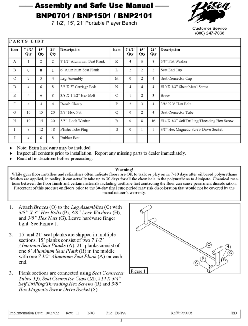
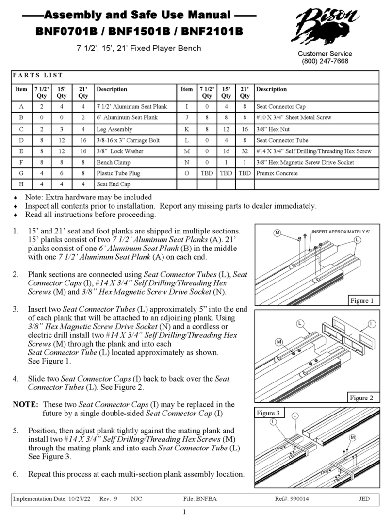
Bison BNF0701 Quick guide
Other Bison Indoor Furnishing manuals
Popular Indoor Furnishing manuals by other brands
Mocka
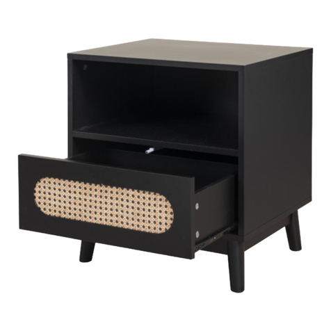
Mocka Claremont Bedside Table Assembly instructions
LDI
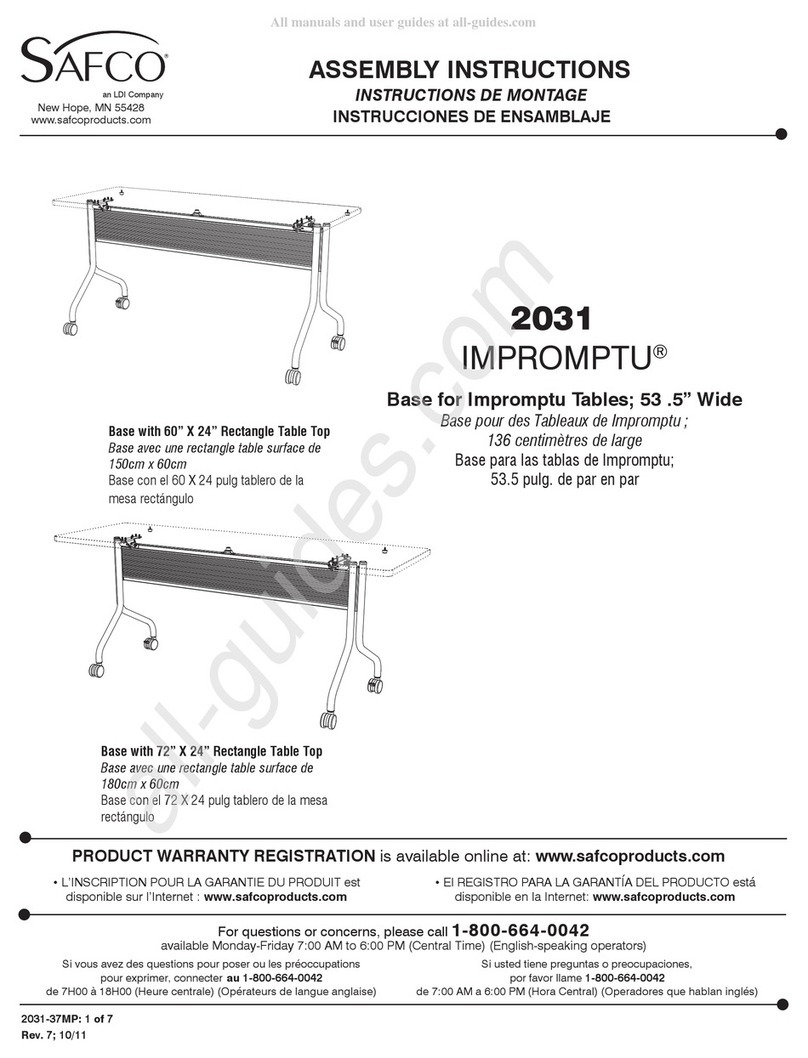
LDI Safco Impromptu 2031 Assembly instructions
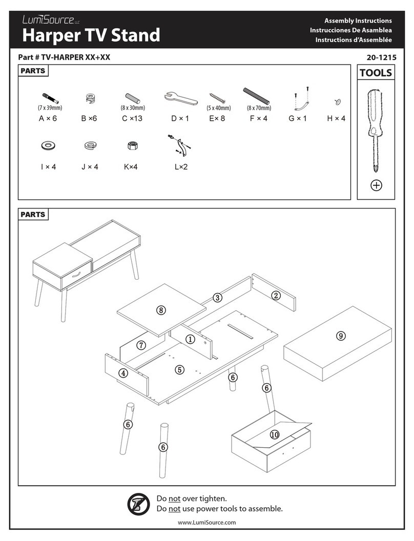
LumiSource
LumiSource TV-HARPER Series Assembly instructions
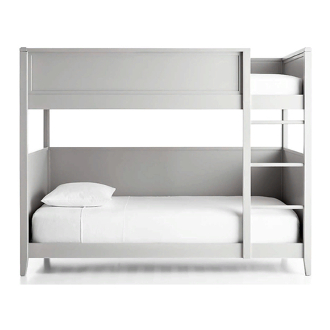
Crate&Barrel
Crate&Barrel Small Space Bunk Bed Assembly instructions

Dorel Home Products
Dorel Home Products 4120139WE manual
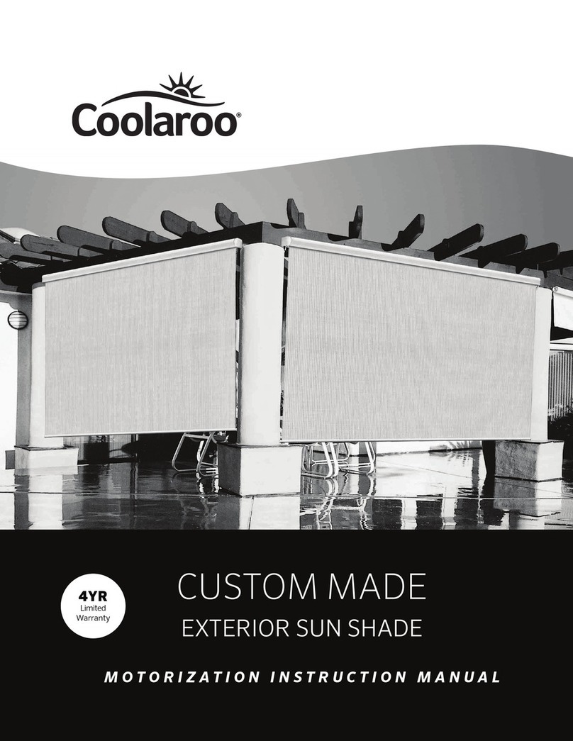
Coolaroo
Coolaroo AutoSun Custom Made instruction manual
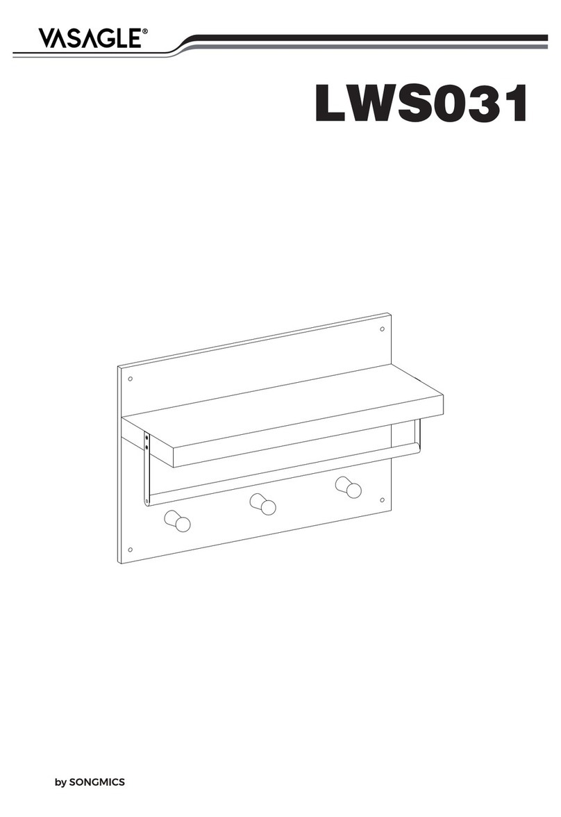
Songmics
Songmics VASAGLE LWS031 manual

Forte
Forte CTGV531 Assembling Instruction

Sauder
Sauder Steel River 423976 Instruction booklet
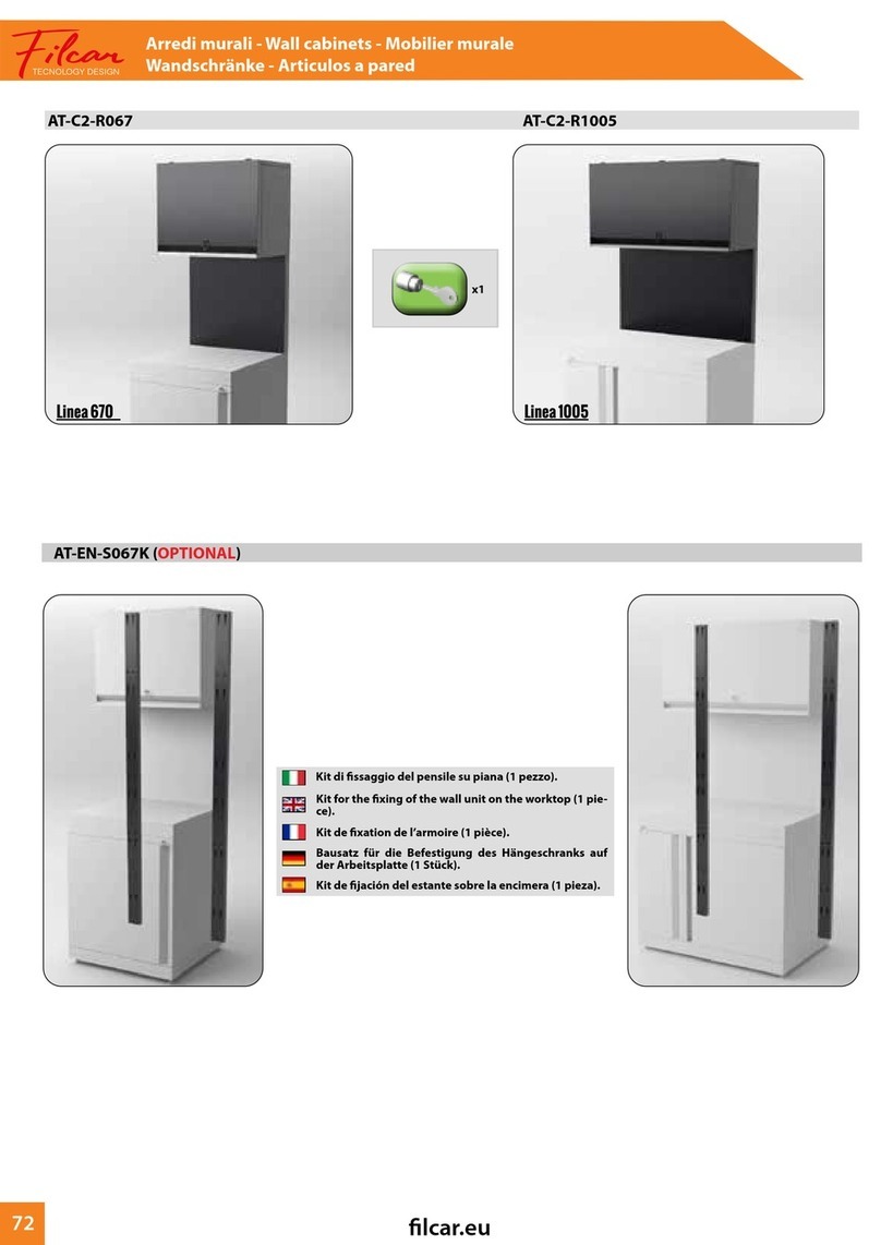
FILCAR
FILCAR Linea 670 AT-C2-R067 Assembly instructions
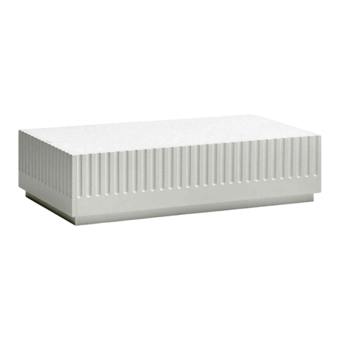
Teulat
Teulat Doric 14951 TE Assembly instructions

Amart Furniture
Amart Furniture BROOKHAVEN 72570 Assembly instruction
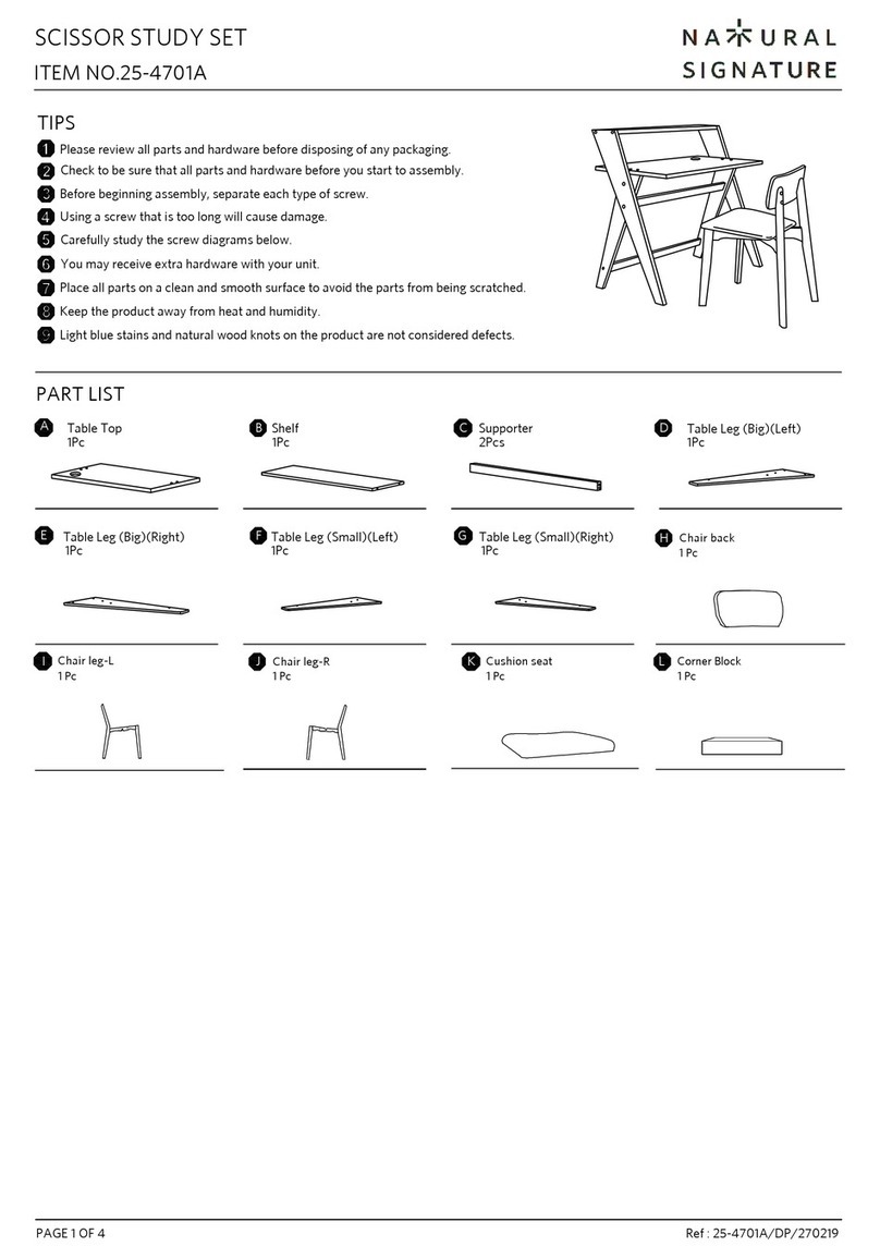
Natural Signature
Natural Signature 25-4701A quick start guide

Hillsdale Furniture
Hillsdale Furniture EASTMAN ADJUSTABLE BARSTOOL 5350-830 Assembly instructions
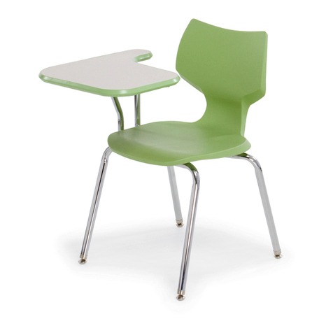
SMITH SYSTEM
SMITH SYSTEM Flavors P-Tablet Assembly instructions
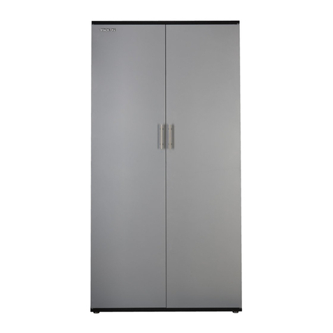
Stack-On
Stack-On GORTA-7203 Assembly
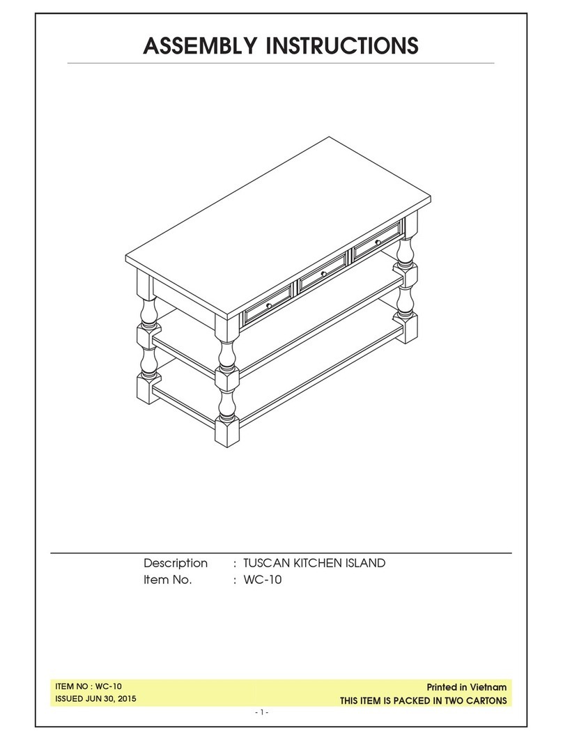
Unfinished Furniture of Wilmington
Unfinished Furniture of Wilmington WC-10 Assembly instructions
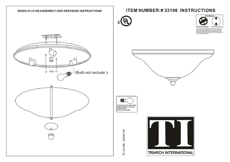
Triarch
Triarch Indoor Lighting 33196 instructions


