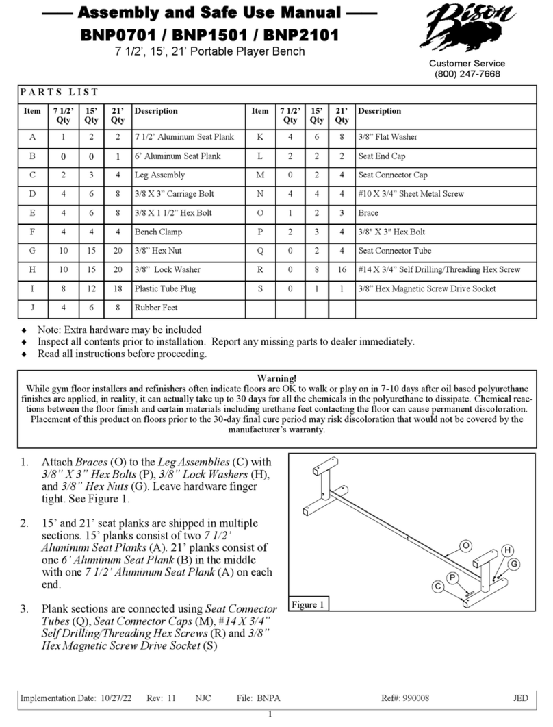
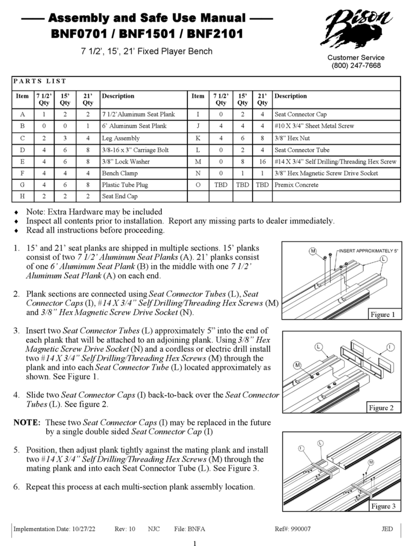
Bison BNF0701B Quick guide
Other Bison Indoor Furnishing manuals
Popular Indoor Furnishing manuals by other brands

DS Produkte
DS Produkte 01128 instructions
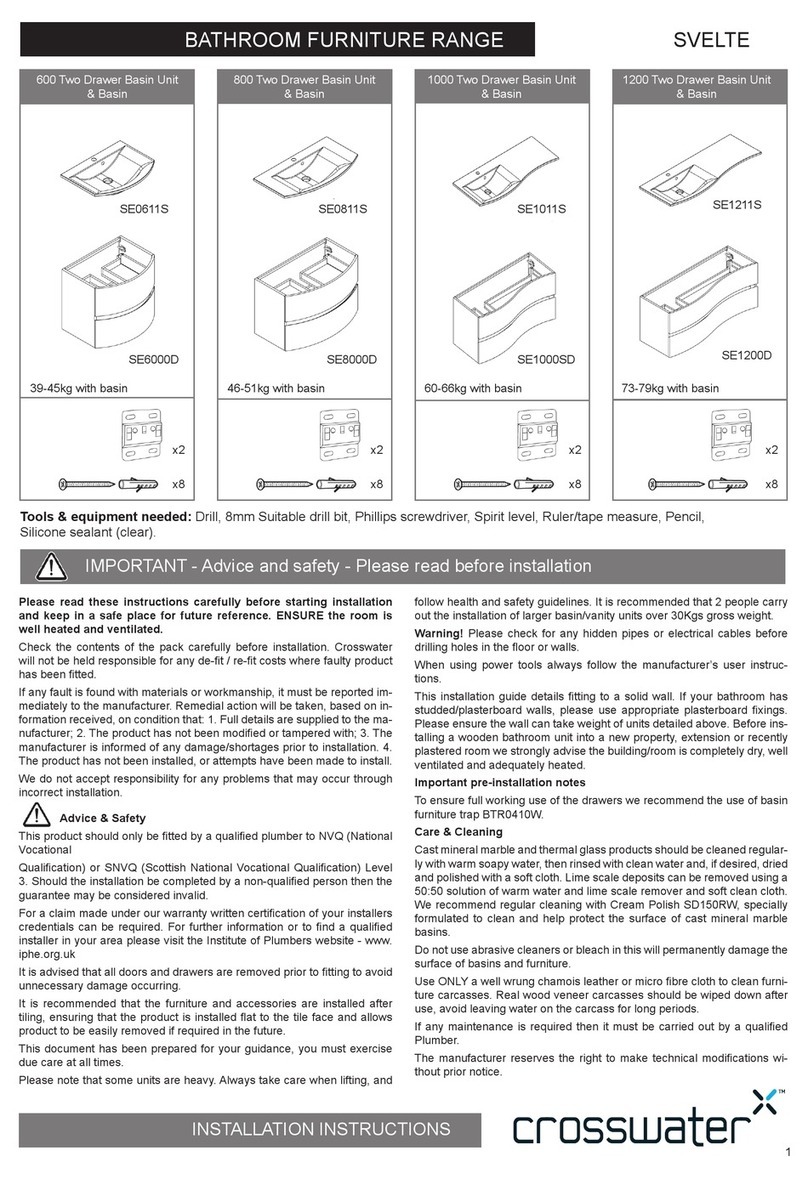
Crosswater
Crosswater SVELTE 600 Series installation instructions
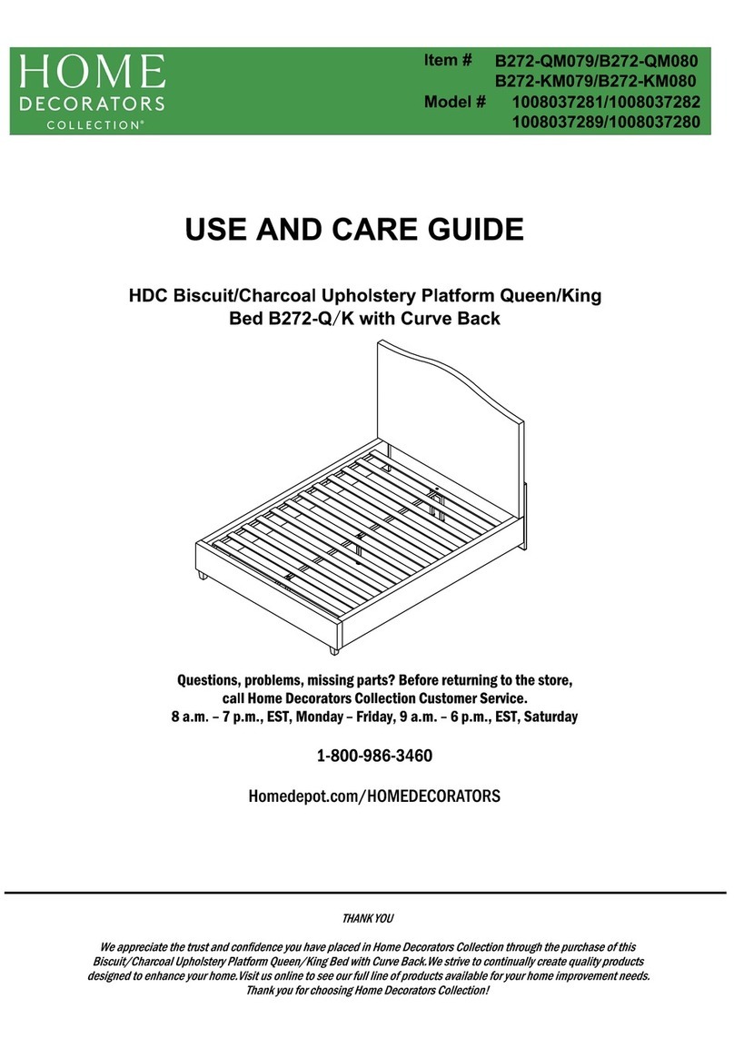
Home Decorators Collection
Home Decorators Collection B272-QM079 Use and care guide
CANARMNA
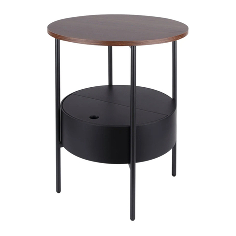
CANARMNA HUTTON 203494-04TZ Assembly instruction
FMD Furniture
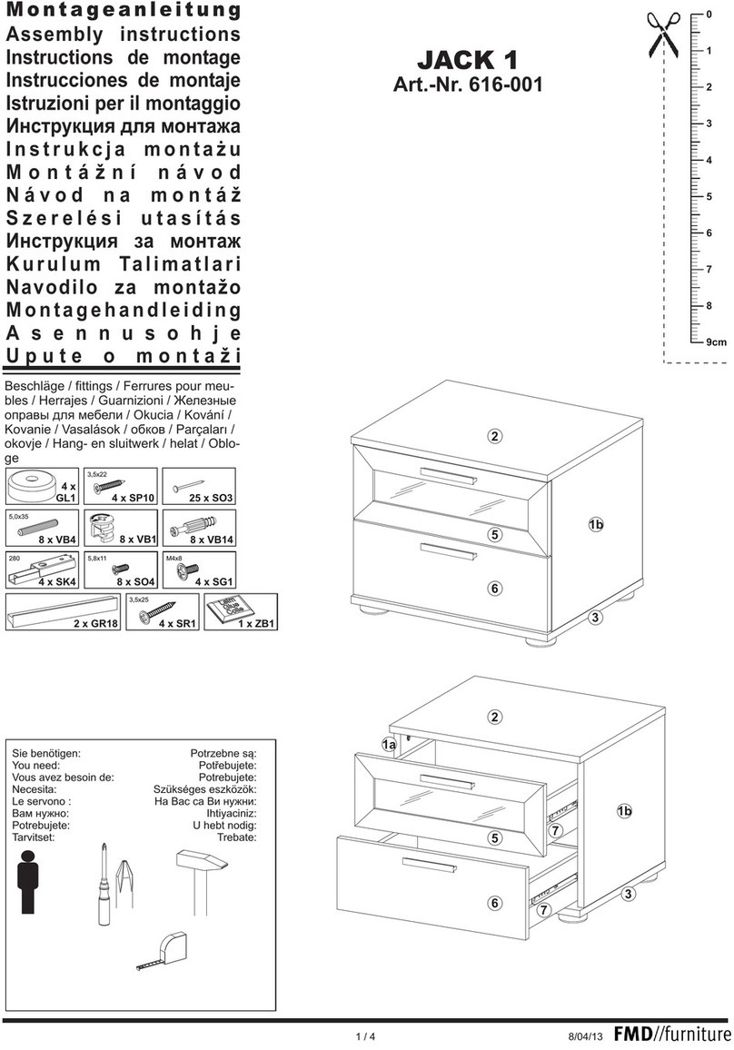
FMD Furniture JACK 1 616-001 Assembly instructions

Walker Edison
Walker Edison BR52DAP6D Assembly instruction

Cooper Lighting
Cooper Lighting Interior Wall Luminaire 673 Specification sheet

Dorel Living
Dorel Living BELMONT DA1026P-18 Instruction booklet

DTY
DTY INDOOR LIVING Cortez IF-1060 quick start guide
Donco
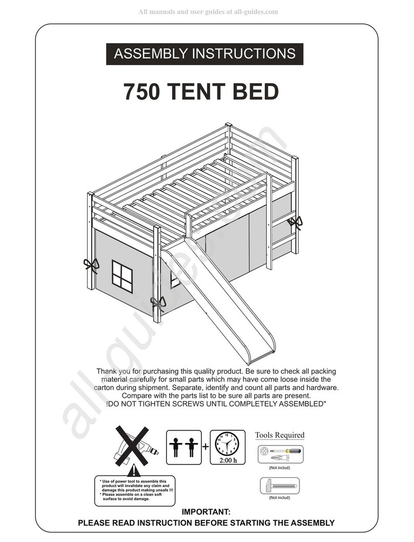
Donco 750 TENT BED Assembly instructions

Home Decorators Collection
Home Decorators Collection WYNDOVER GC-41101-AAT Use and care guide
RiverRidge
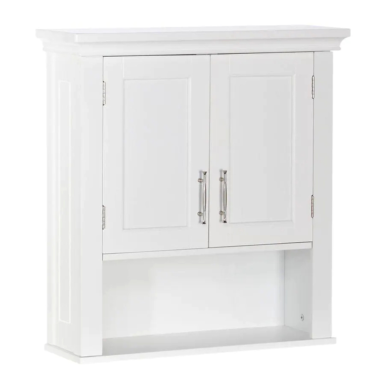
RiverRidge Somerset 06-039 Assembly instructions
Cooper Lighting
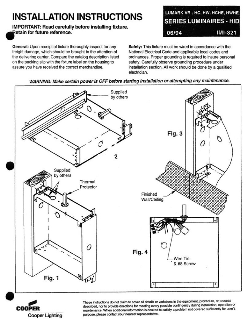
Cooper Lighting IMI-321 installation instructions

Dorel Home Products
Dorel Home Products 4234019WE Instruction booklet
URBAN OUTFITTERS
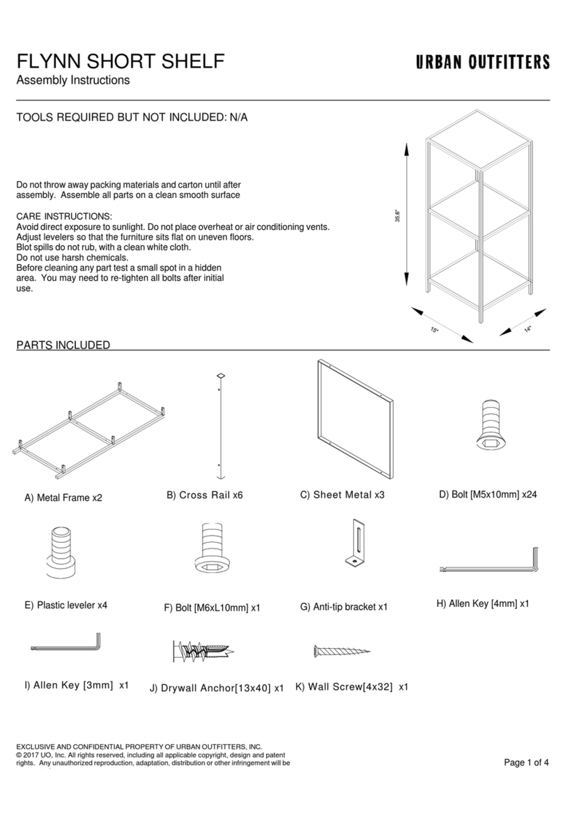
URBAN OUTFITTERS FLYNN SHORT SHELF Assembly instructions
Uplift Desk
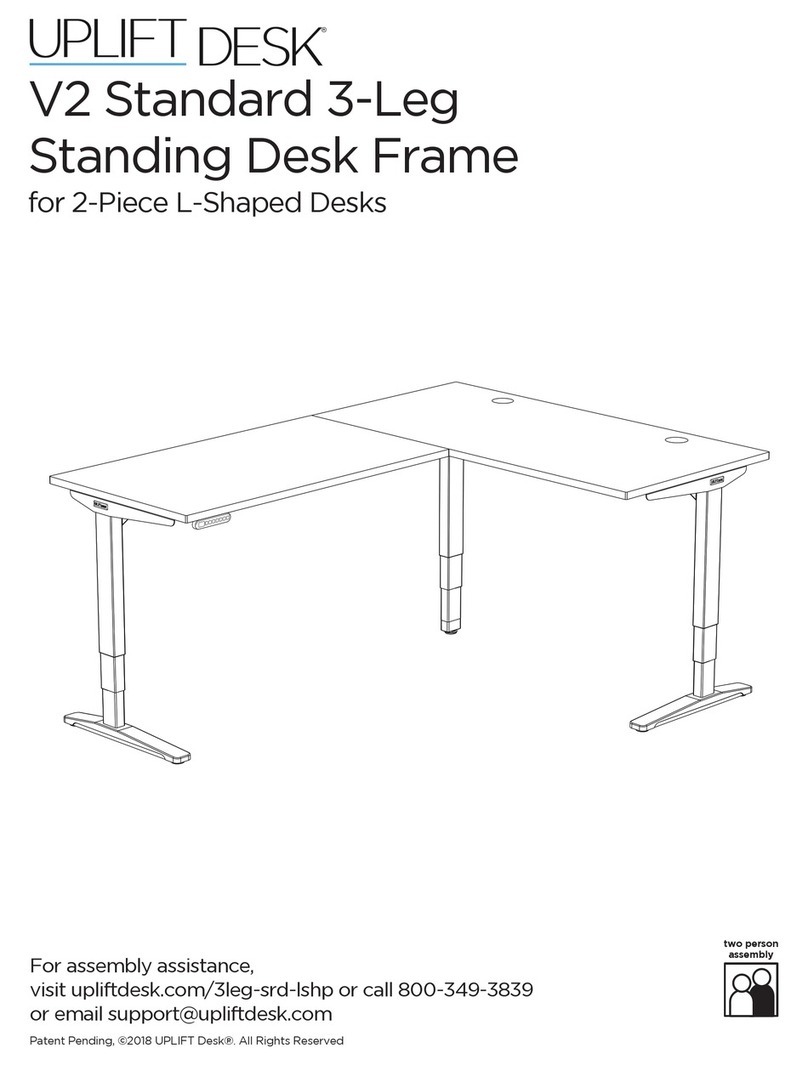
Uplift Desk V2 manual

Sunnydaze Decor
Sunnydaze Decor MERANTI FRN-893 Assembly instructions

Safavieh Furniture
Safavieh Furniture Lucas AMH6501A quick start guide


