manuals.online logo
Brands
  1. Home
  2. •
  3. Brands
  4. •
  5. Bison
  6. •
  7. Indoor Furnishing
  8. •
  9. Bison BNP0701 Quick guide

Bison BNP0701 Quick guide

1
P A R T S L I S T
Item 7 1/2’
Qty
15’
Qty
21’
Qty
Description Item 7 1/2’
Qty
15’
Qty
21’
Qty
Description
A1227 1/2’ Aluminum Seat Plank K4683/8” Flat Washer
B0016’ Aluminum Seat Plank L222Seat End Cap
C234Leg Assembly M024Seat Connector Cap
D4683/8 X 3” Carriage Bolt N444#10 X 3/4” Sheet Metal Screw
E4683/8 X 1 1/2” Hex Bolt O123Brace
F444Bench Clamp P2343/8" X 3" Hex Bolt
G10 15 20 3/8” Hex Nut Q024Seat Connector Tube
H10 15 20 3/8” Lock Washer R0816 #14 X 3/4” Self Drilling/Threading Hex Screw
I812 18 Plastic Tube Plug S0113/8” Hex Magnetic Screw Drive Socket
J468Rubber Feet
 Note: Extra hardware may be included
 Inspect all contents prior to installation. Report any missing parts to dealer immediately.
 Read all instructions before proceeding.
Implementation Date: 10/27/22 Rev: 11 NJC File: BNPA Ref#: 990008 JED
Customer Service
(800) 247-7668
—— Assembly and Safe Use Manual ——
BNP0701 / BNP1501 / BNP2101
7 1/2’, 15’, 21’ Portable Player Bench
Warning!
While gym floor installers and refinishers often indicate floors are OK to walk or play on in 7-10 days after oil based polyurethane
finishes are applied, in reality, it can actually take up to 30 days for all the chemicals in the polyurethane to dissipate. Chemical reac-
tions between the floor finish and certain materials including urethane feet contacting the floor can cause permanent discoloration.
Placement of this product on floors prior to the 30-day final cure period may risk discoloration that would not be covered by the
manufacturer’s warranty.
1. Attach Braces (O) to the Leg Assemblies (C) with
3/8” X 3” Hex Bolts (P), 3/8” Lock Washers (H),
and 3/8” Hex Nuts (G). Leave hardware finger
tight. See Figure 1.
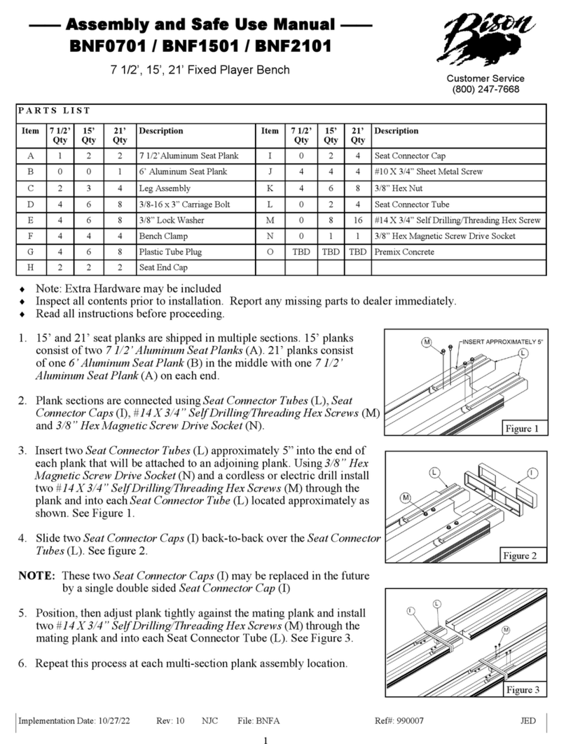
2. 15’ and 21’ seat planks are shipped in multiple
sections. 15’ planks consist of two 7 1/2’
Aluminum Seat Planks (A). 21’ planks consist of
one 6’ Aluminum Seat Plank (B) in the middle
with one 7 1/2’ Aluminum Seat Plank (A) on each
end.
3. Plank sections are connected using Seat Connector
Tubes (Q), Seat Connector Caps (M), #14 X 3/4”
Self Drilling/Threading Hex Screws (R) and 3/8”
Hex Magnetic Screw Drive Socket (S)
Figure 1
2
4. Insert two Seat Connector Tubes (Q) approximately 5” into the end
of each plank that will be attached to an adjoining plank. Using 3/8”
Hex Magnetic Screw Drive Socket (S) and a cordless or electric drill
install two #14 X 3/4” Self Drilling/Threading Hex Screws (R)
through the plank and into each Seat Connector Tube (Q), locate
approximately as shown. See Figure 2.
5. Slide two Seat Connector Caps (M) back to back over the Seat
Connector Tubes (Q). See Figure 3.
NOTE: These two Seat Connector Caps (M) may be replaced in the
future by a single double sided Seat Connector Cap (M)
6. Position, then adjust plank tightly against the mating plank and
install two #14 X 3/4” Self Drilling/Threading Hex Screws (R)
through the mating plank and into each Seat Connector Tube (Q).
See Figure 4.
7. Repeat this process at each multi-section plank assembly location.
8. Attach Leg Assemblies (C) to the Seat Plank Assemblies from above
using 3/8” X 3” Carriage Bolts (D), 3/8” Lock Washers (H), 3/8”
Hex Nuts (G) and Bench Clamps (F). Use Seat Connector Tubes (Q)
on the center legs in place of Bench Clamps (F). Legs should be
spaced 71” center to center with equal plank lengths extending
beyond the other legs on 7 1/2’ models. On 15’ and 21’ models the
planks will extend beyond the legs more on one end than the other
due to the plank connection hardware. See Figure 5.
9. If you want the bench to be portable attach the Rubber Feet (J) to the
Leg Assemblies (C) with 3/8” X 1 1/2” Hex Bolts (E), 3/8” Flat
Washers (K), 3/8” Lock Washers (H) and 3/8” Hex Nuts (G)
See Figure 6.
10. If you want the bench to be fixed, anchor each Leg
Assembly (C) in 2 places using the appropriate anchors (not
included) for the mounting surface. See Figure 6.
11. Insert Plastic Tube Plugs (I) in Leg Assemblies (C).
See Figure 5.
12. Install Seat End Caps (L) using #10 X 3/4” Sheet Metal
Screws (N). See Figure 7.
Figure 6
Figure 2
Figure 3
Figure 4






Figure 5
Figure 7

This manual suits for next models

2

Other Bison Indoor Furnishing manuals

Bison MUSICA PRO User manual

Bison

Bison MUSICA PRO User manual

Bison BNF0701B Quick guide

Bison

Bison BNF0701B Quick guide

Bison Dolce Vita 3641301 ff User manual

Bison

Bison Dolce Vita 3641301 ff User manual

Bison BNF0701 Quick guide

Bison

Bison BNF0701 Quick guide

Popular Indoor Furnishing manuals by other brands

Timbers 6151015C0 Assembly instructions

Timbers

Timbers 6151015C0 Assembly instructions

BENE DOCK-IN BAY TWIN BAY Assembly instructions

BENE

BENE DOCK-IN BAY TWIN BAY Assembly instructions

FMD Furniture LILLY 1 Assembly instructions

FMD Furniture

FMD Furniture LILLY 1 Assembly instructions

Wilson & Fisher MONTERRA quick start guide

Wilson & Fisher

Wilson & Fisher MONTERRA quick start guide

DHP 4188439WE manual

DHP

DHP 4188439WE manual

Furniture of America FGI-2070C21 Assembly instructions

Furniture of America

Furniture of America FGI-2070C21 Assembly instructions

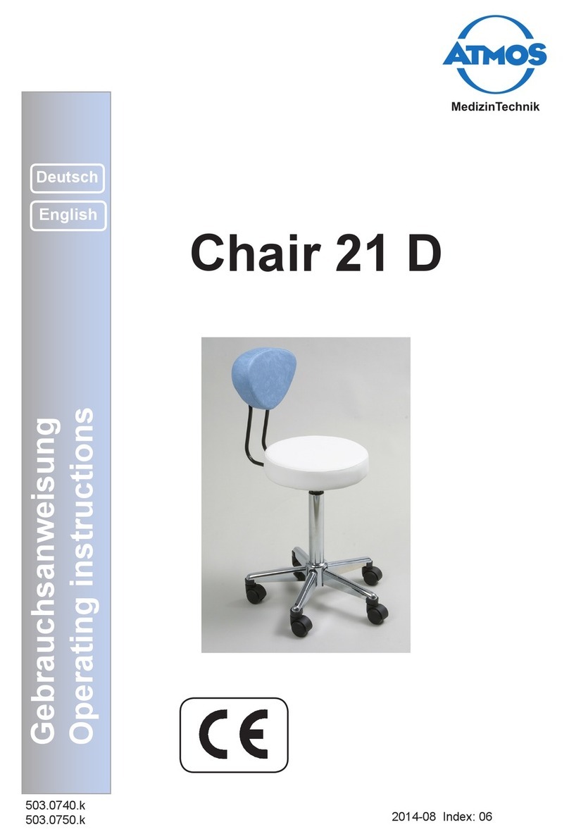
Atmos 21 D operating instructions

Atmos

Atmos 21 D operating instructions

modway EEI-2538 Assembly instructions

modway

modway EEI-2538 Assembly instructions

Furniture of America CM3882PC - 2PK Assembly instructions

Furniture of America

Furniture of America CM3882PC - 2PK Assembly instructions

DITALIA CD-232 Assembly instructions

DITALIA

DITALIA CD-232 Assembly instructions

aspenhome I597-9100 Assembly instructions

aspenhome

aspenhome I597-9100 Assembly instructions

Forte CERK232 Assembling Instruction

Forte

Forte CERK232 Assembling Instruction

SJC brands tasman eco Vouge Assembly instruction

SJC brands

SJC brands tasman eco Vouge Assembly instruction

IKEA SÄLLSKAP manual

IKEA

IKEA SÄLLSKAP manual

IKEA FLÄRKE BOOKCASE 23X67" instructions

IKEA

IKEA FLÄRKE BOOKCASE 23X67" instructions

IKEA PATRULL KLÄMMA instructions

IKEA

IKEA PATRULL KLÄMMA instructions

Vogue CE151 instruction manual

Vogue

Vogue CE151 instruction manual

SHANGRI-LA ROBIN SLROBI6CDWA user guide

SHANGRI-LA

SHANGRI-LA ROBIN SLROBI6CDWA user guide

manuals.online logo
manuals.online logoBrands
  • About & Mission
  • Contact us
  • Privacy Policy
  • Terms and Conditions

Copyright 2025 Manuals.Online. All Rights Reserved.