BISSETT BF-MC0070 User manual
PORTABLE
AIR COMPRESSOR
BF-MC0070
USER MANUAL

2
Introduction
4Using the Operator’s Manual
4 Specications
Product Identication
5 Record Identication Numbers
Safety
6Receipt and Inspection
7Safety Instructions
7 Hazard Symbols and Meanings
8Air Tank Warning
8Fire Warnings
8 Breathable Air Warning
9Electric Shock Warning
9Air Tools and Accessories Warning
10 General Safety Information
11 Spraying Precautions
11 Hose Precautions
Components
12 BF-MC0070
TABLE OF CONTENTS

3
Starting
13 Preparation for Starting
Operation
14 Operation and Adjustment
Caution
15 Caution
Maintenance
16 Maintenance
Troubleshooting
17 Troubleshooting
Exploded View
18 BF-MC0070
19 BF-MC0070 Parts List
20 Pump Breakdown & Parts List
Warranty
22 Warranty
TABLE OF CONTENTS
4
Using the Operator’s manual
Thank you for purchasing our Air Compressor. Your machine is designed for
long life, dependability, and the top performance you demand! Please take
time now to read through this manual so you better understand the machine’s
operation, maintenance and safety precautions.
Everyone who operates this machine must read and understand this manual.
The time you take now will prolong your machine’s life and prepare you for its
safe operation. Enjoy the exceptional performance of your Air Compressor, the
industry leader!
The manufacturer reserves the right to make improvements in design and/or
changes in specications at any time without incurring any obligation to install
them on units previously sold.
Attention: Read through the complete manual prior
to the initial use of your compressor.
Item Data
Model BF-MC0070
Power 3.0HP
Voltage 120V
Frequency 60Hz
Motor Poles 2P
Rated Speed 680 r/min
Current 15A
Delivery 7.0CFM@40psi 5.6CFM@90psi
Discharge Pressure 125 PSI/0.86MPa
Theoretic Discharge
Dischage Discharge
Pressure Discharge
Delivery (at
115PSI/0.8MPa)
8.6CFM/244L/min
Air Outlet Size 1/4”
SPECIFICATIONS
INTRODUCTION

5
PRODUCT IDENTIFICATION
Record Identication Numbers
Compressor
If you need to contact an Authorized Dealer or Customer Service line
(604-545-0252) for information on servicing, always provide the
product model and identication numbers.
You will need to locate the model and serial number for the machine and
record the information in the places provided below.
Date of Purchase:
Dealer Name:
Dealer Phone:
Product Identication Numbers
Model Number:
Serial Number:

6
Receipt and Inspection
Before signing the delivery receipt, inspect for damage and missing parts. If
damage or missing parts are apparent, make the appropriate notation on the
delivery receipt, then sign the receipt. Immediately contact the carrier for an
inspection. All material must be held in the receiving location for the carrier’s
inspection. Delivery receipts that have been signed without a notation of
damage or missing parts are considered to be delivered “clear.” Subsequent
claims are then considered to be concealed damage claims. Settle damage
claims directly with the transportation company.
If you discover damage after receiving the air compressor (concealed
damage), the carrier must be notied within 15 days of receipt and an
inspection must be requested by telephone with conrmation in writing. On
concealed damage claims, the burden of establishing that the compressor
was damaged in transit reverts back to the claimant. Read the compressor
nameplate to verify it is the model ordered, and read the motor nameplate
to verify it is compatible with your electrical conditions. Make sure electrical
enclosures and components are appropriate.
SAFETY

7
SAFETY
The safety alert symbol ( ) is used with a signal word (DANGER, CAUTION,
WARNING), a pictorial and/or a safety message to alert you to hazards.
DANGER: WILL cause DEATH, SEVERE INJURY or substantial
property damage.
WARNING: CAN cause DEATH, SEVERE INJURY or substantial
property damage.
CAUTION: WILL or CAN cause MINOR INJURY or property damage.
NOTICE: indicates a situation that could result in equipment damage.
Follow safety messages to avoid or reduce the risk of injury or death.
Save these Instructions
SAFETY RULES
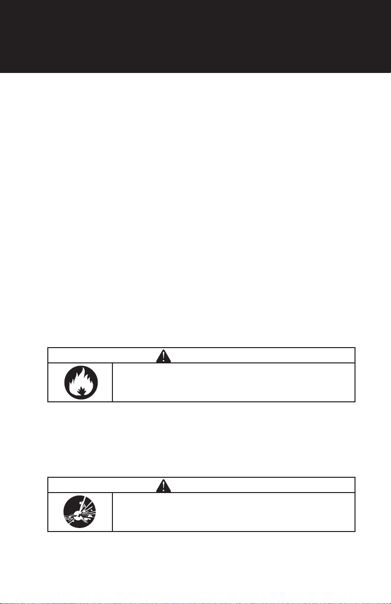
Hazard Symbols and Meanings
This is the safety alert symbol. It is used to alert you
to potential personal injury hazards. Obey all safety
messages that follow this symbol to avoid possible
injury or death.
EXPLOSION
FALL
KICKBACK
FIRE
FLUID INJECTION
HOT SURFACE
ELECTRIC SHOCK
MOVING PARTS
WEAR EYE
PROTECTION
TOXIC FUMES
READ MANUAL
SLIPPERY
8
SAFETY
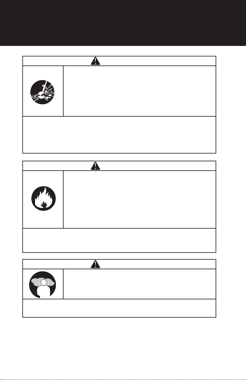
WARNING
AIR TANK WARNING: Drain liquid from air tank daily, or
after each use, using the drain valve located on the bottom
of the lower air tank. Failure to properly drain liquid from the
tank will cause rust from moisture buildup, which weakens
the tank and could lead to a violent tank explosion.
Periodically inspect the tanks for unsafe conditions such
as corrosion.
Never attempt to repair or make modications to the tank or its attachments.
Welding, drilling or any other modications may weaken the tank, which
may result in damage from rupture or explosion. Never remove or attempt
to adjust the pressure switch, safety valve, or other factory set operating
pressures.
WARNING
FIRE WARNING: Avoid dangerous environments.
Do not use compressor near gasoline or other ammable
materials. Keep work area well lit. Normal sparking of a
motor or sparking from grinding metal could ignite fumes.
Do not spray ammable materials in the vicinity of an open
ame or other ignition source, including the air compressor
itself. Do not direct paint or other spray material towards
the compressor.
Read and follow all safely instructions for the material you are spraying.
Be sure to use an approved respirator designed for use with your specic
application.
WARNING
BREATHABLE AIR WARNING: This air compressor is not
designed, nor intended for the supply of breathable air. Air
produced by this unit may contain carbon monoxide or
other toxic vapors.
Do not inhale air from the compressor or from a breathing device
connected to it.
9
SAFETY
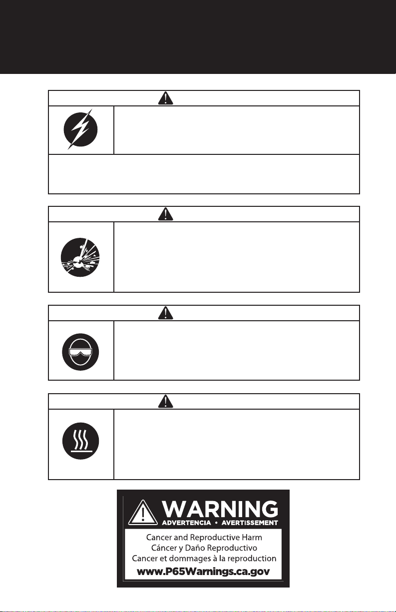
WARNING
ELECTRIC SHOCK WARNING: When using electric
powered tools, machines or equipment, basic safety
precautions should always be followed to minimize the risk
of electrical shock or personal injury to yourself and others.
This air compressor is powered by electricity and should never be used
without properly grounded electrical connections. Do not use in wet or
damp locations or expose to rain.
WARNING
AIR TOOLS AND ACCESSORIES WARNING: Do not
exceed the pressure rating of any air tools, spray guns,
air accessories, or inatables. Excess pressure can cause
them to explode, resulting in serious injury. Follow the
manufacturers recommended pressure settings for all air
tools and air accessories.
WARNING
Do not direct compressed air stream at people or pets.
The powerful compressed air stream can damage
exposed skin and easily propel loose dirt and other small
objects. Always wear eye protection that meets
ANSI Z28.1 specications.
WARNING
Keep hands and ngers away from exposed metal parts
on a running air compressor. Air compressors generate
signicant heat during normal operation, which can cause
serious burns. The compressor will remain hot for some
time after operation and should not be touched or moved
until cool.

10
SAFETY
GENERAL SAFETY INFORMATION
Do not operate unit if damaged during shipping, handling, or use. Damage
may result in bursting and cause injury or property damage.
Since the air compressor and other components (lters, lubricators, hoses,
etc.) used make up a high pressure pumping system, the following safety
precautions must be followed at all times:
1. Read all manuals included with this product carefully. Be thoroughly
familiar with the controls and the proper use of the equipment.
2. Follow all local electrical and safety codes.
3. Only persons well acquainted with these rules of safe operation should be
allowed to use the compressor.
4. Keep visitors away and NEVER allow children in the work area.
5. Wear safety glasses and use hearing protection when operating the
pump or unit.
6. Do not stand on or use the pump or unit as a handhold.
7. Before each use, inspect compressed air system and electrical components
for signs of damage, deterioration, weakness or leakage. Repair or replace
defective items before using.
8. Check all fasteners at frequent intervals for proper tightness.
9. Keep ngers away from a running compressor; fast moving and hot parts
will cause injury and/or burns.
10. If the equipment should start to abnormally vibrate, STOP the engine/
motor and check immediately for the cause. Vibration is generally a sign
of trouble or a aw within the machine.
11. To reduce re hazards, keep engine/motor exterior free of oil, solvent,
or excessive grease. Never remove or attempt to adjust safety valve.
Keep safety valve free from paint and other accumulations.
WARNING
Compressor parts may be hot even if the unit is stopped.
WARNING
Motors, electrical equipment and controls can cause
electrical arcs that will ignite a ammable gas or vapor.
Never operate or repair in or near a ammable gas or vapor.
Never store ammable liquids or gases in the vicinity of the
compressor.
11
SAFETY
WARNING
Do not spray ammable materials in vicinity of open ame
or near ignition sources including the compressor unit.
12. Never attempt to repair or modify a tank! Welding, drilling or any other
modication will weaken the tank, resulting in damage from rupture or
explosion. Always replace worn or damaged tanks. Drain liquid from tank
daily.
13. Tanks rust from moisture build-up, which weakens the tank. Make sure
to drain tank daily and inspect periodically for unsafe conditions such as
rust formation and corrosion.
14. Fast moving air will stir up dust and debris which may be harmful.
Release air slowly when draining moisture or depressurizing the
compressor system.
SPRAYING PRECAUTIONS
15. Do not smoke when spraying paint, insecticides, or other ammable
substances.
16. Use a face mask/respirator when spraying and spray in a well ventilated
area to prevent health and re hazards.
17. Do not direct paint or other sprayed material at the compressor. Place the
compressor as far away from the spraying area as possible to minimize
overspray accumulation on the compressor.
18. When spraying or cleaning with solvents or toxic chemicals, follow the
instructions provided by the chemical manufacturer.
HOSE PRECAUTIONS
19. Inspect hose before use. Do not exceed working pressure marked on
hose. Do not twist, bend knot, or abrade hose. Do not wrap hose around
body.
20. Keep away from hot surfaces and chemicals.
WARNING
Arcing Parts. Keep the compressor/motor at least 6m away
from explosive vapour.

12
Components
BF-MC0070
1.
2.
3.
4.
5.
7.
11.
10.
9.
1. Feet
2. Tank
3. Pressure Gauge
4. Coupler
5. Handle
6. Pully Shroud
7. Filter
8. Motor
9. Safety Valve
10. Wheels
11. Drain Plug
COMPONENTS
6.
8.

13
Starting
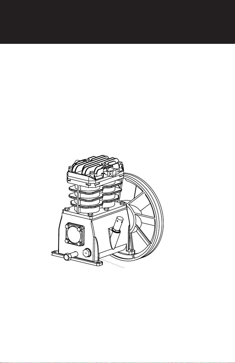
PREPARATION FOR STARTING
1. The place to set the compressor should be clean, dry and ventilated.
2. Keep the oil level in the red circle leveler.
3. Recommended Oil use SAE 30W non-detergent compressor oil.
STARTING

14
Operation
OPERATION AND ADJUSTMENT
The output pressure of compressed air can be adjusted by regulating
valve. Pull up the knob of regulation valve and turn it clockwise or
counterclockwise to increase or decrease the pressure
Pressure
Switch
Pressure
Gauge
Safety
Valve
Regulating
Valve
Bleeder
Valve
Button
Handle
ON/OFF
OPERATION

15
Caution
1. Put the cover off rst and put on the breath pipe and air lter before the
compressor run (Fig.3).
2. Never unscrew any connecting part when the tank is in pressure
condition.
3. Never disassemble any electrical part before disconnecting the plug.
4. Never adjust the safety valve carelessly.
5. Never use the compressor in place where voltage is too low or too high.
6. Never disconnect the plug to stop compressor, set the switch knob in
position off instead.
7. If the release valve doesn’t work as motor stopped, nd the cause
immediately so as not to damage motor.
8. Lubricating oil must be clean, oil level should be kept in the score of oil
ruler.
9. Disconnect the plug to cut off power supply and open the outlet valve.
Breath
Pipe
Air Filter
Port
Oil-hole
FIG.3
CAUTION
16
Maintenance
1. Clean crankcase and renew lubricating oil after the rst 10 working hours.
2. Clean the oil level after every 20 working hours, and replenish if
necessary (Fig.4)
3. Open drain cock under the tank to exhaust condensate after every 60
working hours.
4. Clean crankcase and renew the oil, clean air lter, and check safety valve
and pressure gauge after every 120 working hours.
Oil-hole
FIG.4
MAINTENANCE

17
Troubleshooting
Trouble Possible causes Remedies
Sticking of main
compressor 1. Moving parts burnt due
to the oil insufcient
2. Moving parts damaged,
or stuck by foreign body.
Check crankshaft,
bearing, connecting rod,
piston, piston ring, etc,
And replace if necessary.
Terrible shake or
abnormal noise 1. Connecting part loosed
2. Foreign body got into
main compressor
3. Piston knocking valve
seat
4. Moving parts seriously
worn
1. Check and retighten
2. Check and clean away
3. Replace with thicker
paper gasket
4. Repair or replace
Pressure
insufcient
or discharge
capacity
decreased
1 Motor running too slow
2. Air lter chocked up
3. Leakage of safety valve
4. Leakage of discharge
pipe
5. Sealing gasket damaged
6. Valve plate damaged,
carbon buildup or stuck.
7. Piston ring and cylinder
worn or damaged
1. Check and remedy
2. Clean or replace the
cartridge
3. Check and adjust
4. Check and repair
5. Check and replace
6. Replace and clean
7. Repair or replace
The oil
Consumption too
excessive
1. Oil level too high
2. Breath pipe chocked up
3. Piston ring and cylinder
worn or damaged
1. Keep the level within
set range
2. Check and clean
3. Repair or replace
TROUBLESHOOTING

18
Exploded View
BF-MC0070
EXPLODED VIEW
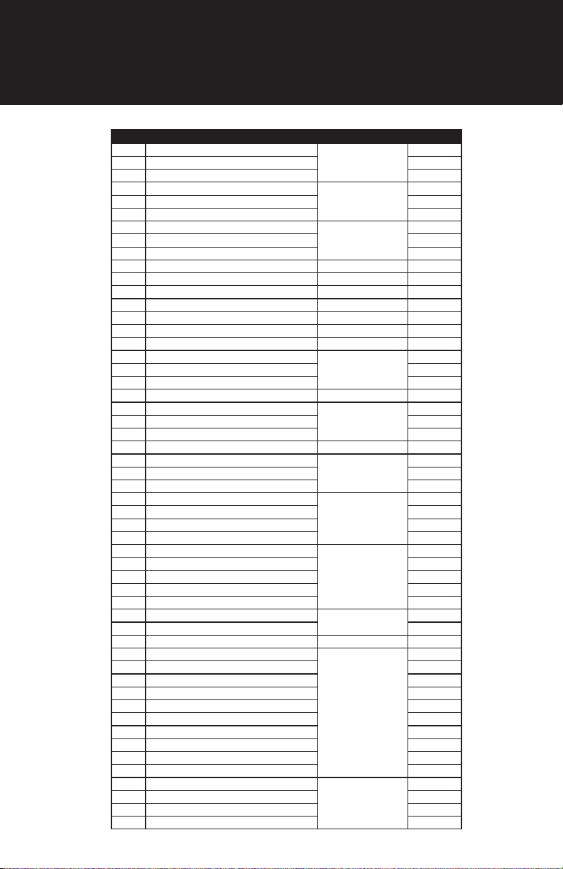
19
EXPLODED VIEW
REF DESCRIPTION PART NUMBER QTY.
2GRIP, HANDLE
42.004.500
1
11 GRIP, HANDLE 1
47 SCREW 2
2GRIP, HANDLE
42.004.501
1
11 GRIP, HANDLE 1
47 SCREW 2
2GRIP, HANDLE
42.004.502
1
11 GRIP, HANDLE 1
47 SCREW 2
3 PRESSURE GAUGE 42.003.006 1
4 SAFETY VALVE 42.006.046 1
5 PRESSURE SWITCH 42.004.519 1
7 REGULATOR 42.0010.010 1
8 PRESSURE GAUGE 42.003.005 1
9 T-BRANCH PIPE 42.000.018 1
10 COUPLER 42.000.046 2
12 FOOT RUBBER PAD
42.004.505
2
13 6 FLAT WASHER 2
14 BOLT 2
15 DRAIN COCK 42.004.012 1
16 BOLT
42.004.506
2
17 TANK WHEEL 2
18 SIX ANGLE NUT 2
19 EXHAUST PIPE ASSEMBLY 42.004.521 1
20 CONRADER CHECK VALVE
42.005.066
1
21 UNLOAD COPPER PIPE 1
22 UNLOAD ELBOW 0.4M
23 SIX ANGLE NUT
42.004.510
4
24 SPRING WASHER 4
25 BOLT 4
26 PUMP 1
27 MOTOR BOLT
42.004.511
4
28 WASHER 4
29 SIX ANGLE NUT 4
48 CABLE GLANDS 1
32 MOTOR 1
30 IN-SIX ANGLE BOLT 42.004.512 1
31 MOTOR PULLEY 1
33 V-BELT 42.004.513 1
34 SAFETY GUARD
42.004.514
1
35 SAFETY GUARD 1
36 WASHER 2
37 SPRING WASHER 2
38 BOLT 2
39 SCREW 2
40 SIX ANGLE NUT 1
41 HOLDER 1
42 SCREW 1
43 SCREW, M6X1X16 1
40 SIX ANGLE NUT
42.004.515
1
41 HOLDER 1
42 SCREW 1
43 SCREW, M6X1X16 1

20
EXPLODED VIEW (PUMP)
Table of contents
Other BISSETT Air Compressor manuals

Popular Air Compressor manuals by other brands

Rolair
Rolair JC10 owner's manual

Orban
Orban 412A operating manual

California Air Tools
California Air Tools Industrial 6010LFC owner's manual

Chicago Pneumatic
Chicago Pneumatic HP 20 Use & maintenance manual

WABCO
WABCO System Saver 318 Maintenance manual

Clarke
Clarke Boxer 14/100P Operation & maintenance instructions


F.F. Group
F.F. Group AC-D 24/2MC EASY Original instructions

Gude
Gude 260/10/24 ST Translation of the original instructions

AirTech
AirTech OIL-LubePortableAir Compressor user manual

Ring Automotive
Ring Automotive RAC700 instructions

Craftsman
Craftsman 921.16475 owner's manual

Sears
Sears Craftsman 919.167463 owner's manual