BISSETT BF-MC0060 User manual
HIGH CFM
AIR COMPRESSOR
BF-MC0060
USER MANUAL

2

3
Introduction
4Using the Operator’s Manual
Product Identication
5 Record Identication Numbers
Safety
6Receipt and Inspection
6Description
7Safety Instructions
7 Hazard Symbols and Meanings
8Warnings
Installation
10 Mechanical
10 Electrical
10 Motor
10 Reset Switch
11 Pressure Switch
11 Air Pressure Regulator
11 Grounding
12 Extension
Lubrication
12 Oil Filling
12 Oil Change
Start Up
13 Procedure
Maintenance
14 Daily
14 Weekly
14 Quarterly or 300 Hours
Storage
14 Procedure
Troubleshooting
15 Troubleshooting Chart
Exploded View
17 Exploded View
Parts List
18 Parts List
Warranty
20 Warranty
TABLE OF CONTENTS

4
Using the Operator’s manual
Thank you for purchasing a Bissett Fasteners Limited High CFM Air Compressor.
Please take time now to read through this manual so you better understand the
machine’s operation, maintenance, and safety precautions.
Everyone who operates this machine must read and understand this manual.
The time you take now will prolong your machine’s life and prepare you for its safe
operation.
The manufacturer reserves the right to make improvements in design and/or changes
in specications at any time without incurring any obligation to install them on units
previously sold.
Attention: Read through the complete manual prior to the
initial use of your compressor.
INTRODUCTION

5
PRODUCT INDENTIFICATION
Record Identication Numbers
Compressor
If you need to contact an Authorized Dealer or Customer Service line
(604-545-0252) for information on servicing, always provide the
product model and identication numbers.
You will need to locate the model and serial number for the machine and
record the information in the places provided below.
Date of Purchase:
Dealer Name:
Dealer Phone:
Product Identication Numbers
Model Number:
Serial Number:

6
RECEIPT AND INSPECTION
Each air compressor outt is carefully tested and inspected before shipment. Every
attempt is made to ensure safe and complete shipment of our products. It is the
responsibility of the receiver of the goods to ensure the product has been shipped in
full and has arrived in suitable condition. If there are any mechanical issues with your
compressor, please contact us for service.
It is your responsibility to ensure that the air compressor is properly readied for use,
as well as maintained and serviced on a regular basis. Information has been included
in this booklet outlining the suggested air compressor maintenance schedules and a
trouble shooting guide. Be sure to follow the instructions in section 6.1 before turning
your compressor on. It is important that you read this information and keep it in a safe
place for future reference.
DESCRIPTION
The air compressor pump works with the up and down movement of a piston in the
cylinder. During the down-stroke of the piston, ambient air is drawn in through the inlet
valve, while the discharge valve remains closed. During the up-stroke, the air is forced
into the compressor tank through the discharge valve and the check valve. Through
this controlled action, air is forced into the tank to a preset pressure. The pressure is
regulated by the pressure switch. Working air is not available until the pressure in the
air tank built up. The air inlet lter openings must be kept clear of obstructions.
All tools require specic air pressure to operate properly. Consult your air tool manual
for those requirements and safety instructions. There are a variety of air tools available
that will operate efciently with this air compressor. For best results, always compare
the air tool requirements to your compressor output specications. A tool that requires
a lot of continuous air, such as a sander, will not operate effectively with a small tank
compressor. A tool that requires little air, such as a brad nail gun, will operate with a
small tank compressor very effectively. Learn your air tool power requirements, match
your air tools to your compressor correctly and this compressor will perform effectively.
SAFETY

7
SAFETY
The safety alert symbol ( ) is used with a signal word (DANGER, CAUTION,
WARNING), a pictorial and/or a safety message to alert you to hazards.
DANGER: WILL cause DEATH, SEVERE INJURY or substantial
property damage.
WARNING: CAN cause DEATH, SEVERE INJURY or substantial
property damage.
CAUTION: WILL or CAN cause MINOR INJURY or property damage.
NOTICE: indicates a situation that could result in equipment damage.
Follow safety messages to avoid or reduce the risk of injury or death.
Save these Instructions
SAFETY RULES
Hazard Symbols and Meanings
This is the safety alert symbol. It is used to alert you
to potential personal injury hazards. Obey all safety
messages that follow this symbol to avoid possible
injury or death.
EXPLOSION
FALL
KICKBACK
FIRE
FLUID INJECTION
HOT SURFACE
ELECTRIC SHOCK
MOVING PARTS
WEAR EYE
PROTECTION
TOXIC FUMES
READ MANUAL
SLIPPERY

8
WARNING
• Do not spray combustible or ammable liquid or paint within a
conned area. Spray area must be well ventilated.
• Do not smoke while spraying or spray where spark or ame is
present.
• Keep compressor at least 12 ~ 18 feet away from spraying area
and all explosive vapors.
WARNING
• Disconnect compressor from electrical supply circuit before
servicing.
• Do not expose compressor to rain or operate in a wet area.
• Never use the air compressor without connection to a properly
grounded outlet with the specied voltage and fuse protection.
• Improper grounding can result in electrical shock.
WARNING
• Drain tank daily. Condensed water will cause rusting and risk of
tank rupture or explosion.
• Do not repair, modify or weld tank. Return to authorized service
center if replacement is required.
• Do not adjust regulator to result in output pressure greater than
marked max. Pressure of attachment.
• Pressure switch is set at the factory for optimum performance of
your particular model. Never bypass or remove pressure switch
as serious damage to equipment or personal injury could result
from too high of pressure.
• Before starting compressor, pull safety valve ring to make sure
the valve moves freely. The safety valve is factory installed
to prevent the air receiver from damage should malfunction
occur in the pressure switch. It is factory set at a specic limit
for your particular model, and should never be tampered with.
Adjustment by user will automatically void warranty.
WARNINGS
SAFETY

9
WARNING
• Hot surface can cause serious injury. Never touch any exposed
metal parts on compressor during or immediately after
operation. Touching these areas may cause severe burns.
• Do not reach around protective shrouds or attempt maintenance
until unit has been allowed to cool.
WARNING
• Do not use compressed air for breathing. When spraying use
respiratory protection in a well ventilated area.
• Compressor air from the unit may contain poisonous vapors
which is not suitable for inhaling and could be harmful to your
health.
• Work in an area with good ventilation.
WARNING
• Unit starts automatically. Do not operate with guards or covers
removed or broken.
• Any repair required on the product should be performed by
authorized service center personnel.
• Do not touch moving parts.
WARNING
• Always wear ansi z87.1 Approved safety glasses with side
shields when use the air compressor. Always wear proper
safety equipment while using compressed air.
• Do not direct air stream toward any parts of the body or at other
people.
• Unplug power cord and drain all air pressure from tank before
servicing and after each use.
SAFETY
WARNING
• Always place compressor on a protective mat when transporting to protect
against damage to vehicle from leaks.
• Never operate compressor on a roof or other elevated positions.
• Always operate compressor in a stable position to prevent accidental movement
of the unit.

10
Installation
MECHANICAL
Use the compressor in a clean, dry and well ventilated area. The compressor should
be located 12 ~ 18 inches from a wall or any other obstruction that would interfere
with the air ow cooling function. Place the air compressor on a rm and level surface.
The air compressor is designed with heat dissipation ns that allow for proper cooling.
Keep the ns and other parts that collect dust or dirt clean. A clean compressor runs
cooler and promotes longer life. Allow room for easy access to the air compressor for
maintenance and service work. Air tool power requirements, match your air tools to
your compressor correctly and this compressor will perform effectively.
ELECTRICAL
It is your responsibility to ensure that the air compressor is connected to power source
in a safe and correct manner. Any electrical work should be carried out by a licensed
electrician and installed in a way that meets all applicable codes and regulations.
Failure to connect the air compressor correctly to power source may result in serious
personal injury or damage to the equipment.
Please note that under normal conditions, the air compressor will operate
intermittently. Should it be necessary to service your air compressor, ensure the power
source has been shut down. This must be done to prevent personal injury or damage
to the unit.
If the supply cord is damaged, it must be replaced by your dealer or all warranties and
liabilities are void.
MOTOR
Wiring must be completed in a manner that the full voltage nameplate ±10% is
available at the motor terminals during startup. Use of an incorrect power source
will result in premature motor failure and is not covered by this compressor or motor
manufacturer’s warranty.
RESET SWITCH
Ensure that all guards and shrouds are in place before pressing reset switch to restart
the motor. If the motor shuts down because of overload, wait 10-15 minutes for the
motor to cool down, then press the reset switch to restart motor. The reset switch
button is located on the motor housing.
INSTALLATION
11
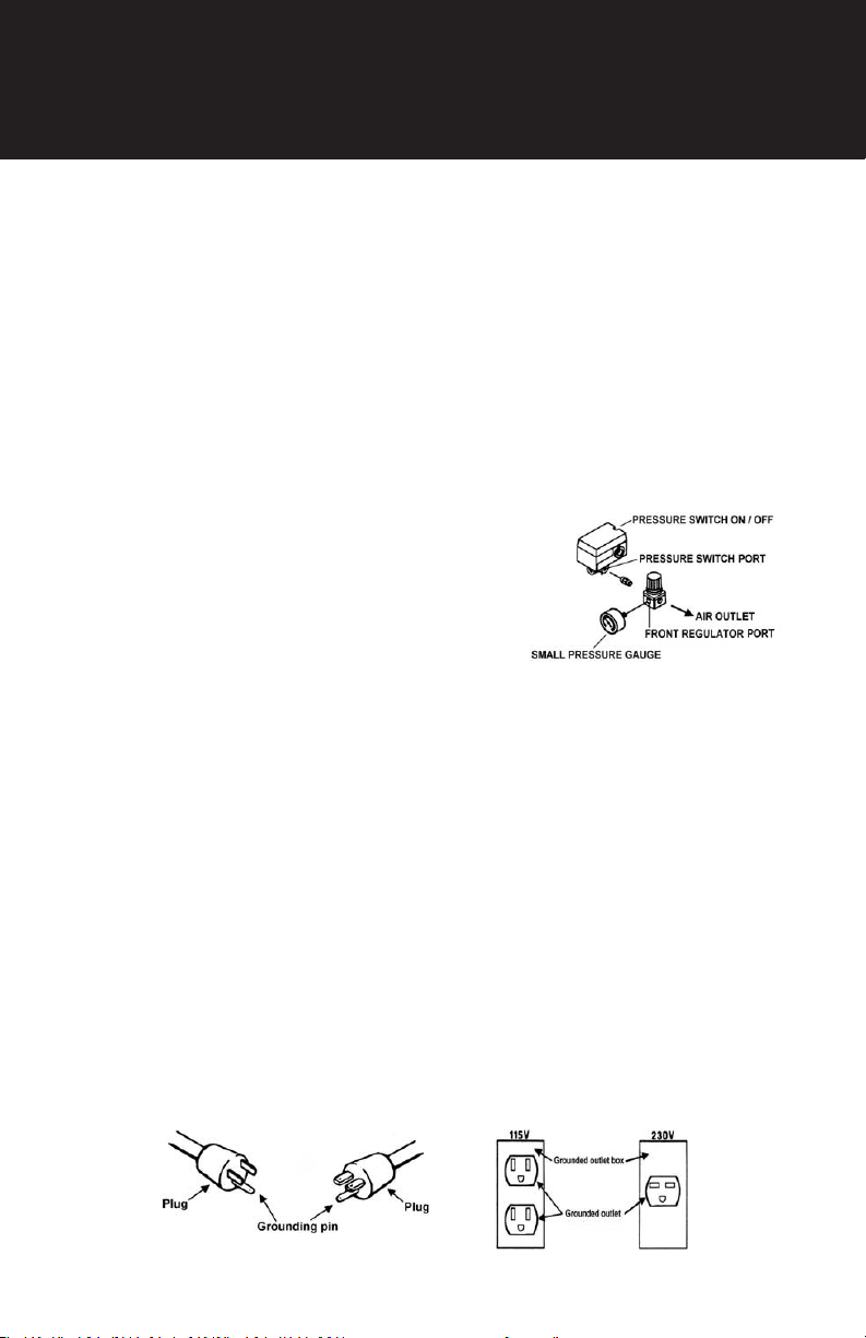
PRESSURE SWITCH
The pressure switch acts as a pilot device activating the motor. The pressure switch
cut in/cut out has been preset at the factory, do not tamper with the settings. Never
bypass or remove this switch, as serious damage to equipment or personal injury could
result from improper pressure setting. Consult your local distributor or service center if
the switch malfunctions.
This pressure switch houses the “AUTO”, or “ON” switch as well as the “OFF” switch.
The term “AUTO” is used because it activates the motor and allows the pump to operate
until the compressor reaches the preset pressure. Once up to the preset pressure,
the motor stops and switches to standby mode. After air is bleed off through use of
otherwise, the pressure switch then will kick the motor back into operation so the proper
air pressure will always be maintained. Thus, the
compressor does have current readily available to
operate the pump, and will draw on the electrical
supply automatically upon need.
Always set this switch to “OFF” when the
compressor is not in use and before unplugging
compressor.
AIR PRESSURE REGULATOR
The air pressure regulator enables you to adjust outlet pressure to the tool in use. Never
exceed maximum working pressure of the tool. To adjust, turn clockwise to increase
pressure, or turn counterclockwise to decrease pressure to the tool. Turn the thread nut
against knob to lock in place.
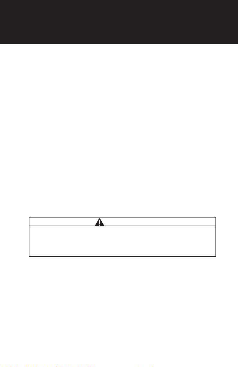
GROUNDING
Do not modify the plug that has been provided. If it does not t the available outlet, the
correct outlet should be installed by a qualied electrician. The plug must be plugged
into an outlet that is properly installed and grounded in accordance with all local codes. If
these grounding instructions are not completely understood, or if in doubt as to whether
the compressor is properly grounded, have the installation checked by a qualied
electrician.
This product is for use on a nominal 115 or 230 volt circuit, as applicable. A cord with a
grounding plug as shown here must be used. Make sure that the product is connected
to an outlet having the same conguration as the plug. No adapter should be used with
this product.
INSTALLATION

12
EXTENSION CORDS
The use of any extension cord will cause some drop in voltage and loss of power. Do
not use an extension cord unless absolutely necessary. It is better to use a long air hose
to reach area where work is being performed. If use of an extension cord can not be
avoided, refer to the following guidelines before using.
Use only 3-wire extension cord that has a 3-blade grounding plug. Make sure your
extension cord is in good condition. Be sure gauge is sufcient to carry the current the
unit will draw. Note that the smaller the gauge the heavier the cord. Example: Gauge 10
is heavier than gauge 12. Do not use 14 or 16 AWG for extension cord.
Lubrication
OIL FILLING
1. Remove the oil ller plug.
2. Slowly pour the proper oil into the pump crankcase.
3. Always keep oil level between the marks “High” and “Low” level on the oil dipstick
(or on the red circle of the sight glass).
OIL CHANGE
Change oil after the rst 8 hours of compressor operation, then change oil after every
300 working hours or 3 months whichever comes rst.
1. Remove the oil drain plug and allow oil to drain out. Used oil should be handled by
recycle agents.
2. Replace the oil drain plug. The use of a sealing compound or Teon tape to avoid
leakage is recommended.
3. Rell with the recommended oil to the proper level.
LUBRICATION
13
Start Up
PROCEDURE
Do not attempt to operate the air compressor without rst checking the oil level
in the pump.
Drain and replace oil as required. Serious damage may result from running without oil.
1. Check to see that all nuts and bolts are snug.
2. Check that compressor is on a stable level surface.
3. Check that air lter is clean.
4. Do not place any materials on or against the compressor.
5. Open the drain valve at the bottom of the tank.
6. Turn the pressure switch lever to “AUTO”.
7. Ensure air is escaping from the drain valve. Allow the unit to operate for a minimum
of twenty minutes in this no load condition.
8. After running the compressor for twenty minutes, close the drain valve and allow
the unit to reach maximum operating pressure. Ensure that the compressor shuts
down at the preset maximum pressure. Notice that the head pressure is released
through the unloading valve of the pressure switch.
9. Check the air compressor and piping systems for leakages.
10. Recheck the oil level in the crankcase. Add oil as required.
11. Your compressor is ready for use.
WARNING
• Before doing any maintenance or adjustments to your air compressor, the
following safety precautions should be taken.
A. Disconnect electrical power.
B. Drain air tank to release air pressure.
START UP

14
Maintenance
DAILY
1. Check oil level.
2. Drain condensation from air tank.
3. Check for any unusual noise or vibration.
4. Be sure all nuts and bolts are tight.
WEEKLY
1. Clean air lter. Replace air lter if necessary.
QUARTERLY OR 300 HOUR
1. Change compressor oil and air lter element.
2. Check safety valve.
3. Check pressure switch unloads to ensure compressor head unloads whenever
motor shuts down.
4. Clean and blow off pump ns and motor.
5. Inspect air system for leaks by applying soapy water to all joints.
Storage
PROCEDURE
1. Set the “AUTO/OFF” switch to “OFF” and unplug the compressor.
2. Be sure to drain the water from the air tank.
3. Protect the electrical cord and air hose from damage.
4. Store the air compressor in a clean and dry location.
MAINTENANCE

15
Troubleshooting
TROUBLESHOOTING CHART
CONDITION CAUSE CORRECTIVE
Compressor won’t start 1. Loose electrical connection
2. Motor overheated
1. Check wiring connection
2. Press reset button or wait for
automatic reset
Low pressure 1. Air leak in safety valve
2. Loose tube or ttings
3. Restricted air lter
4. Defective check valve
5. Worn out rings
1. Release safety valve manually
by pulling outward on ring.
If condition persists replace
valve
2. Tighten ttings
3. Clean or replace
4. Replace check valve
5. Replace piston rings
Air is releasing from safety valve
continuously
1. Defect pressure switch or
improper adjustment
2. Defective safety valve
1. Check for proper adjustment
and if problem persists replace
pressure switch
2. Replace safety valve
Oil discharge and excessive
carbon formation or appearance
of water and oil in the air lines
1. Improper oil viscosity
2. Overlling the crankcase
with oil
3. Restricted air intake lter
4. Carbon on exhaust valves
5. Worn valves
6. Worn piston rings
7. High ambient temperature and/
or humidity
8. High percentage of running
time
1. Replace oil with SAE 30 Weight
non-detergent compressor oil
2. Drain oil and ll to proper level
3. Clean or replace lter
4. Replace
5. Replace
6. Replace piston rings
7. Install a moisture separator
and/or oil lter
8. Check for air leakage. If no
leaks are found , you may
need an additional compressor
as your air demand is too
much for the existing unit
Excessive noise 1. Loose valve
2. Noisy only during start up,
Check for loose belts
3. Piping loose
4. Unit is on an uneven surface
5. Improper grade of oil in
crankcase
6. Carbon or foreign material on
piston
7. Worn bearings
1. Inspect valve
2. Adjust for proper tension
3. Tighten bolts and nuts as
required
4. Ensure that unit is on level
surface
5. Replace oil with SAE 30
Weight non- detergent
compressor oil
6. Clean piston. Check cylinder
walls for scoring
7. Replace main bearings
TROUBLESHOOTING

16
CONDITION CAUSE CORRECTIVE
Compressor over heating 1. Undersized unit for air
requirements
2. Compressor location
3. Air leaks in the system
4. Restricted air lter
5. Improper grade or level
of oil
6. Worn, damage, or carbon
build up on valve
7. Carbon build up at after-
cooler tube or check valve
1. Contact your dealer /
distributor
2. See installation section
3. Fix leaks
4. Clean or replace lter
5. Replace with SAE 30
Weight non-detergent
compressor oil
6. Clean, repair or replace
valves
7. Clean or replace
Pressure switch unloading
valve does not function or
leak air when unit is operating
or not operating
1. Pressure switch unloading
valve may be dirty or
faulty
2. Check valve may be dirty
or faulty
1. Clean, or replace unloading
valve
2. Clean, or replace check
valve
Water in air tank 1. Condensation in the air tank
during normal usage 1. Drain daily or install an
automatic drain
Oil leaks or appearance of oil
on the compressor 1. Spillage of oil when lling
2. Overlling the crankcase
3. Improper grade of oil
4. Leak at oil ller plug
5. Oil leak at gasket, cylinder
or crankcase
6. Loose plug
7. Loose side or end plate
8. Oil seal leak
1. Wipe unit clean
2. Drain oil and ll to proper
level
3. Replace with proper
SAE 30 non-detergent
compressor oil
4. Tighten or replace oil ller
plug
5. Replace gaskets as
required
6. Tighten plug
7. Tighten plates
8. Replace oil seal
TROUBLESHOOTING

17
EXPLODED VIEW
REF DESCRIPTION QTY. PART NUMBER
1BOLT 4
42.012.010
2SPRING WASHER 8
3PLAIN WASHER 4
6CYLINDER HEAD 1
7GASKET 1
42.012.011
8VALVE PLATE 2
10 VALVE REED 2
11 GASKET 1

18
EXPLODED VIEW

19
PARTS LIST
REF DESCRIPTION QTY. PART NUMBER
64 OUTLET HOSE 1 42.012.008
65 ELBOW 1 42.012.007
65 ELBOW 1
42.012.006
66 END CAP 3
67 PRESSURE SWITCH 1
69 SAFETY VALVE 1
66 END CAP 3
42.012.009
68 GAUGE 2
70 QUICK COUPLER 2
71 REGULATOR 1
72 DRAIN VALVE 1 42.012.000
73 TANK ASSEMBLY 1
74 RUBBER FOOT 2
42.012.00175 PLAIN WASHER 2
76 BOLT 2
77 WHEEL 2
42.012.002
78 WHEEL CUSHION 2
79 WASHER 2
80 BOLT 2
81 SPRING WASHER 2
82 INLET ASSEMBLY 1
42.012.005
83 SEAL GASKET 2
84 STRAIGHT JOINT 1
85 CHECK VALVE 142.005.066
86 ELBOW 1
87 FERRULE 2
42.012.004
88 NUT 1
89 ALUMINUM TUBE 1
90 NUT 1

20
If you need assistance with the
assembly or operation
of your Compressor please call
604-545-0252
WARRANTY
Bissett Fasteners Limited warrants that each new product will be free of any
manufacturerdefects for a period of 2 years. This warranty covers the air tank,
engine, and air pump. Warranty applies to the original purchaser of the product and
cannot be transferred.
This warranty does not cover normal wear items, including but not limited to: seals,
packings, valves, etc. Warranty also does not include normal maintenance like
oil changes, lters or valve adjustments. Nor does it include misuse of product.
Warranty approval is at the sole discretion of Bissett Fasteners Limited.
In no event shall Bissett Fasteners Limited be liable for any indirect, incidental or
consequential damages from the misuse of the product. This disclaimer applies
both during and after the term of this warranty. Bissett Fasteners Limited disclaims
liability for any implied warranties, including implied warranties of merchantability
and tness for a specic purpose, after the applicable term of this warranty.
Table of contents
Other BISSETT Air Compressor manuals

Popular Air Compressor manuals by other brands

Campbell Hausfeld
Campbell Hausfeld IN626100AV operating instructions

DEZEGA
DEZEGA HIHPG2 user manual

King Canada
King Canada 8469 Service manual

Johnson Controls
Johnson Controls Frick NGC 100 Installation operation & maintenance

California Air Tools
California Air Tools 12V1P10S owner's manual

Powermate
Powermate 200-2477 parts manual

CAMPAGNOLA
CAMPAGNOLA Hobby Air Use and maintenance manual

Makita
Makita AC001G instruction manual

Precision Medical
Precision Medical PM15F user manual

Airpress
Airpress LMO 50-270 Silent Instruction manual for owner's use

Sealey
Sealey RE229.V4 quick start guide

GEA Bock
GEA Bock EX-HG44e Series Assembly instructions


