2 Troubleshooting
4WABCO Maintenance Manual 31 (Revised 08-18)
2 Troubleshooting
Hazard Alert Messages
Read and observe all Warning and Caution hazard alert messages in this publication. They provide information that can help prevent serious
personal injury, damage to components, or both.
To prevent serious eye injury, always wear safe eye protection when you perform vehicle maintenance or service.
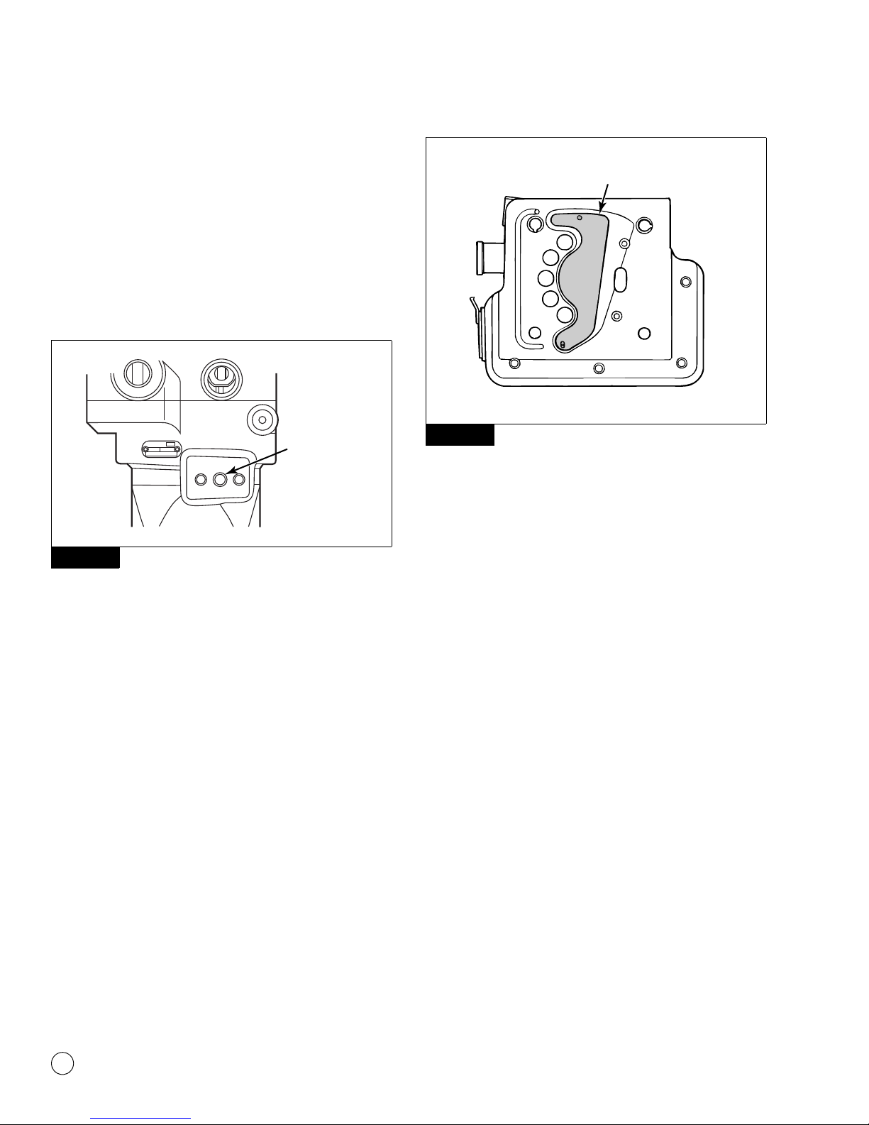
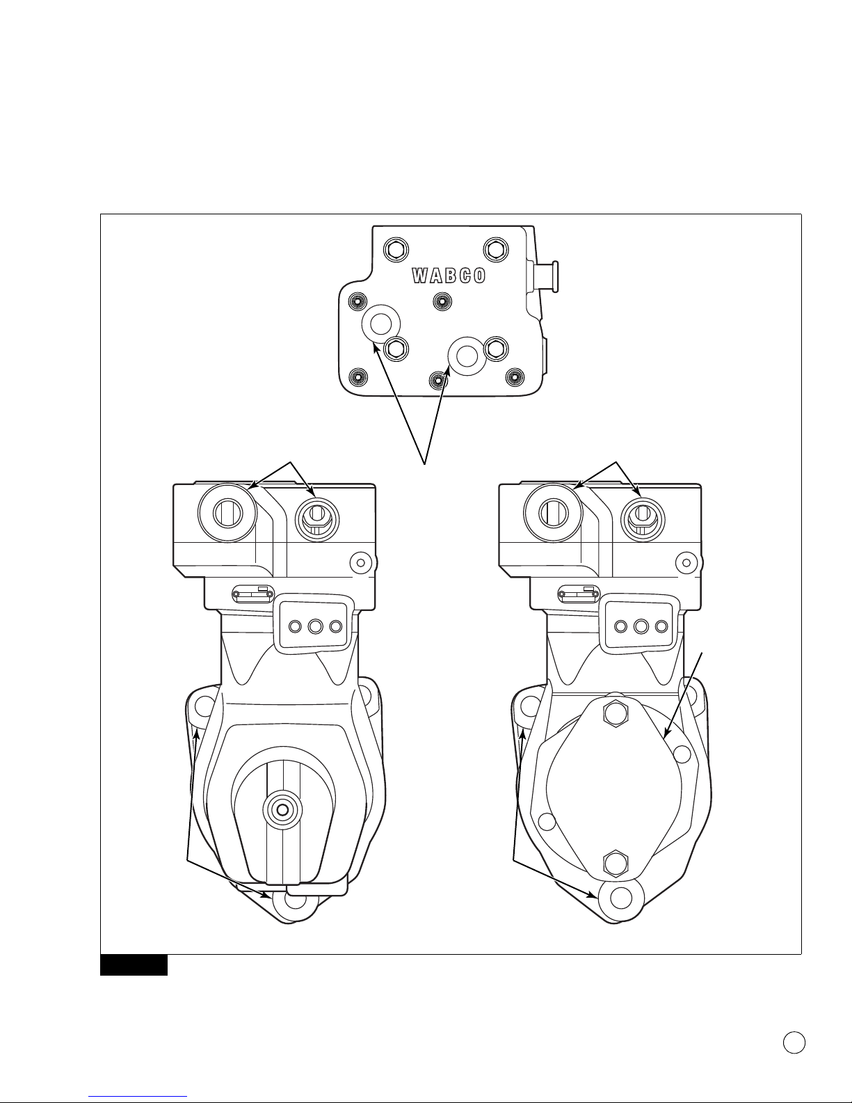
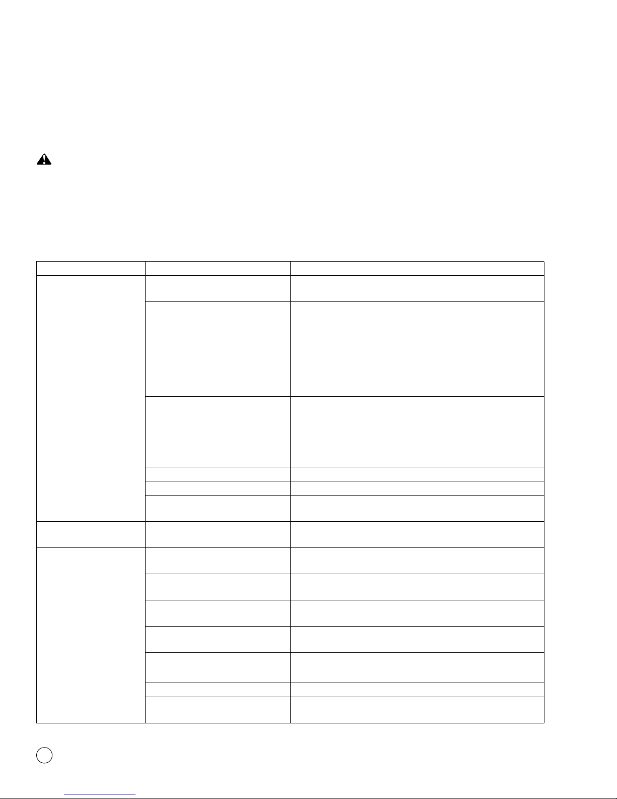
Use Table A to troubleshoot the WABCO System Saver 318 air compressor.
NOTE: If you have any questions or need additional information, please contact WABCO North America Customer Care at 855-228-3203.
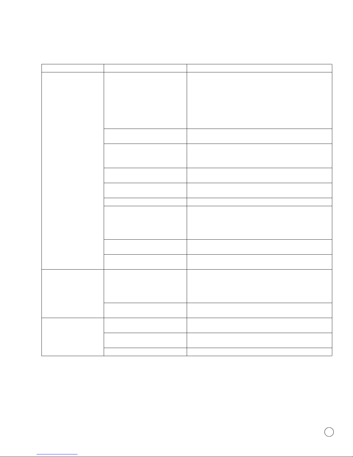
Table A: Compressor Troubleshooting Guide
Condition Possible Cause Solution
Compressor passes
excessive oil (for example,
the presence of oil at
exhaust air brake system
valves, oil in air dryer
desiccant, etc.)
Blocked or restricted oil return Clean oil drain passages in the compressor and on the engine
surface. Verify correct passage alignment.
Contaminated inlet air or oil Replace damaged, defective or dirty engine air filter.
Repair any leaking, damaged or defective compressor air intake
components.
Change engine lubricating oil.
NOTE: To avoid this condition, make sure vehicle manufacturer’s oil
and filter maintenance schedules are followed.
Restricted air inlet or excessive
vacuum present at compressor inlet
Verify engine or compressor air cleaner is functioning correctly.
Replace if necessary.
Repair compressor air inlet kinks or excessive bends.
Check vehicle specifications to ensure air and coolant lines meet all
requirements.
Excessive engine crankcase pressure Verify engine crankcase venting is to manufacturer’s specification.
Compressor duty cycle too high Check system for leaks. Make necessary repairs.
None of the above, but condition
persists
Replace the compressor.
Compressor leaks oil Physical damage or internal problems
with compressor
Replace the compressor.
Compressor continuously
cycles
Compressor unloader piston leaking With compressor unloaded, check for air leakage. If leaking, replace
the cylinder head.
Governor air leak Refer to the manufacturer’s manual for governor maintenance and
troubleshooting procedures.
Dryer purge valve air leakage Check for air dryer malfunction. Refer to air dryer manufacturer’s
service instructions.
Air leak at governor-compressor
attachment
Inspect connection for physical damage. Inspect and repair
connection.
Air leak at alcohol injector Clear line of any obstructions.
Inspect and repair connection.
Excessive reservoir contamination Drain reservoirs.
None of the above, but condition
persists
Replace the compressor.