BizLine BIZ 780 312 User manual

• EN DIGITAL MULTIMETER
InstructionManual...........................................................p.2
Please read this manual before switching the unit on. Important safety
information inside.
• FR MULTIMÈTRE NUMÉRIQUE
Moded'emploi..................................................................p.22
Lisez ce manuel avant d’utiliser l’appareil. Informations importantes de
sécurité à l’intérieur.
• NL DIGITALE MULTIMETER
Gebruiksaanwijzing.....................................................p.42
Lees deze gebruiksaanwijzing voordat u het apparaat inschakelt.
Belangrijke veiligheidsinformatie binnenin.
BIZ 780 312
SE E-nr 42 023 20
Snro 67 045 07
Exe_Notice_BIZ780312_EN-FR-NL.indd 1 15/05/2019 17:37

EN
2
Table of contents Page
1. Introduction 3
2. Safety 3-5
3. Controls and Jacks 5
4. Symbols and Annunciators 6
5. Operating Instructions 7
5-1. DC Voltage Measuments 7
5-2. AC Voltage (Frequency, Duty Cycle) Measurements 8
5-3. MV Voltage Measurements 9
5-4. DC Current Measurements 10
5-5. AC Current (Frequency, Duty Cycle) Measurements 11
5-6. Resistance Measurements 12
5-7. Continuty Check 12
5-8. Diode Test 13
5-9. Temperature Measurements 13
5-10. Frequency / Duty Cycle Measurements (Electronic) 14
5-11. Autoranging / Manual Range Selection 14
5-12. MAX/MIN 14
5-13. Relative Mode 15
5-14. Display Backlight 15
5-15. HOLD 15
5-16. AUTO Power Off 15
5-17. LOW Battery Indication 15
6. Maintenance 16
6-1. Battery Installation 17
6-2. Replacing the Fuses 17
7. Specications 18-21
Exe_Notice_BIZ780312_EN-FR-NL.indd 2 15/05/2019 17:37

EN
3
1. Introduction
This meter measures AC/DC Voltage, AC/DC Current, Resistance, Frequency
(electrical & electronic), Diode Test, and Continuity. It features a waterproof,
rugged design for heavy duty use. Proper use and care of this meter will provide
many years of reliable service.
2. Safety
This symbol adjacent to another symbol, terminal or operating
device indicates that the operator must refer to an explanation in
the Operating Instructions to avoid personal injury or damage to
the meter.
This WARNING symbol indicates a potentially hazardous situation
which if not avoided, could result in death or serious injury.
This CAUTION symbol indicates a potentially hazardous situation
which if not avoided, may result damage to the product.
This symbol advises the user that the terminal(s) so marked must
not be connected to a circuit point at which the voltage with respect
to earth ground exceeds (in this case) 1000 VAC or VDC.
Thissymboladjacenttooneormoreterminals identies themas
being associated with ranges that may, in normal use, be subjected
to particularly hazardous voltages. For maximum safety, the meter
and its test leads should not be handled when these terminals are
energized.
This symbol indicates that a device is protected throughout double
insulation or reinforced insulation.
Test Leads
WARNING : Operation is limited to CAT II
applications when the insulated tips are
removed from one or both test probes.
Refer to input limits section in this manual
for maximum voltage ratings.
Exe_Notice_BIZ780312_EN-FR-NL.indd 3 15/05/2019 17:37

EN
4
IP code if applicable
Safety Instructions
This meter has been designed for safe use, but must be operated with caution.
The rules listed below must be carefully followed for safe operation.
1. NEVER apply voltage or current to the meter that exceeds the specied
maximum:
Input Protection Limits
Function Maximum Input
VDC 1000 VDC RMS
VCA 1000 VAC RMS
mA AC/DC 800 mA 1000 V fast acting fuse
A AC/DC 10 A 1000 V fast acting fuse
(30 seconds max every 15 minutes)
Frequency, resistance, CAP, diode
test, de continuity
250 VDC/AC RMS
Surge Protection : 8 kV peak per IEC 61010
Exe_Notice_BIZ780312_EN-FR-NL.indd 4 15/05/2019 17:37

EN
5
2. USE EXTREME CAUTION when working with high voltages.
3. DO NOT measure voltage if the voltage on the "COM" input jack exceeds
1000V above earth ground
4. NEVER connect the meter leads across a voltage source while the function
switch is in the current, resistance, CAD or diode mode. Doing so can damage
the meter.
5. ALWAYS dischargeltercapacitorsinpowersuppliesanddisconnectthepower
when making resistance or diode tests.
6. ALWAYS turn off the power and disconnect the test leads before opening the
covers to replace the fuse or batteries.
7. NEVER operate the meter unless the back cover and the battery and fuse
covers are in place and fastened securely
8. If the equipment is used in a manner not specied by the manufacturer, the
proctection provided by the equipment may be impaired.
3. Controls and Jacks
1-6000 counts LCD display
2-MAX/MIN button
3-RANGE button
4-Mode button
5-Function switch
6-mA, µA and 10 A input jacks
7-COM input jack
8-Positive input jack
9-HOLD and Backlight button
10-Hz and % button
11-RELATIVE button
Note : Tilt stand and battery compartment are on rear of unit.
Exe_Notice_BIZ780312_EN-FR-NL.indd 5 15/05/2019 17:37

EN
6
4. Symbols and Annunciators
Auto power off
Continuity
Diode test
Battery status
micro (10-9)
milli (10-3)
Amps
kilo (103)
mega (106)
Ohms
Hertz (frequency)
Percent (duty ratio)
Alternating current
Direct current
Volts
Relative
Maximum
Minimum
Autoranging
Display hold
(Frequency conversion measure)
Degrees Fahrenheit
Degrees Centigrade
µ
m
A
k
M
Ω
Hz
%
AC
DC
V
MAX
MIN
Auto Rang
VFD
ºF
ºC
Exe_Notice_BIZ780312_EN-FR-NL.indd 6 15/05/2019 17:37

EN
7
5. Operating Instructions
WARNING : Risk of electrocution. High-voltage circuits, both AC and DC,
are very dangerous and should be measured with great care.
1. ALWAYS turn the function switch to the OFF position when the meter is not
in use.
2. If “OL” appears in the display during a measurement, the value exceeds the
range you have selected. Change to a higher range.
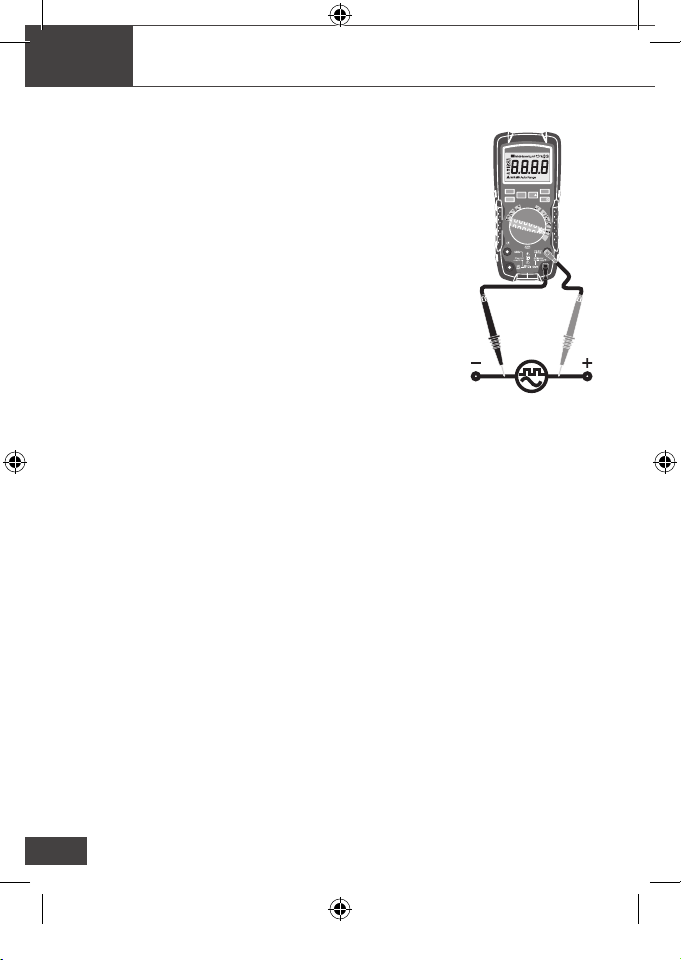
5-1. DC Voltage Measuments
CAUTION : Do not measure DC voltages if a motor on the circuit is being
switched ON or OFF. Large voltage surges may occur that
can damage the meter.
1. Set the function switch to the Vposition.
2. Insert the black test lead banana plug into the
negative COM jack.
3. Insert the red test lead banana plug into the positive
Vjack.
4. Touch the black test probe tip to the negative side of
the circuit.
5. Touch the red test probe tip to the positive side of
the circuit.
6. Read the voltage in the display.
OFF
V
V
10A
mA
A
Auto
Power
Off
8
Temp
VFD
RANGE
MAX/MIN
REL
HZ%
MODE
HOLD
VFD
TRUE RMS Autoranging Digital Multimeter
CAP
V
Temp
°C°F
Exe_Notice_BIZ780312_EN-FR-NL.indd 7 15/05/2019 17:37

EN
8
5-2. AC Voltage (Frequency, Duty Cycle)
WARNING : Risk of Electrocution. The probe tips may not be long enough to
contact the live parts inside some 240V outlets for appliances because the
contacts are recessed deep in the outlets. As a result, the reading may show
0 volts when the outlet actually has voltage on it. Make sure the probe tips are
touching the metal contacts inside the outlet before assuming that no voltage is
present.
CAUTION : Do not measure AC voltages if a motor on the circuit is being
switched ON or OFF. Large voltage surges may occur that can damage the
meter.
1. Set the function switch to the "V-/Hz/%/VFD" position.
2. Indicate "AC" on the display.
3. Insert the black test lead banana plug into the
negative COM jack.
4. Insert red test lead banana plug into the positive
COM jack.
5. Touch the black test probe tip to the neutral side
of the circuit.
6. Touch the red test probe tip to the "hot" side of the
circuit.
7. Read the voltage in the display
8. Press and hold the MODE button key for 2 seconds
to indicate "VFD" on the display.
9. Read the "VFD" value in the display.
10. To exit VFD mode press and hold the MODE
button for 2 seconds.
11. Press the Hz/% button to indicate "Hz".
12. Read the frequency in the display.
13. Press the Hz/% button again to indicate "%".
14. Read the %of duty cycle in the display.
OFF
V
V
10A
mA
A
Auto
Power
Off
8
Temp
VFD
RANGE
MAX/MIN
REL
HZ%
MODE
HOLD
VFD
TRUE RMS Autoranging Digital Multimeter
CAP
V
Temp
°C°F
Exe_Notice_BIZ780312_EN-FR-NL.indd 8 15/05/2019 17:37

EN
9
OFF
10A
mA
A
Auto
Power
Off
8
VFD
RANGE
MAX/MIN
REL
MODE
TRUE RMS Autoranging Digital Multimeter
V
V
Temp
HZ%
HOLD
VFD
CAP
V
Temp
°C°F
5-3. MV Voltage Measurements
CAUTION : Do not measure mV voltages if a motor on the circuit is being
switched ON or OFF. Large voltage surges may occur that can damage the
meter.
1. Set the function switch to the mV/Hz/% position.
2. Press the MODE button to indicate “DC” or “AC”.
3. Insert the black test lead banana plug into the negative
COM jack.
4. Insert the red test lead banana plug into the positive
Vjack.
5. Touch the black test probe tip to the negative side of
the circuit. Touch the red test probe tip to the positive
side of the circuit.
6. Read the mV voltage in the display
7. Press the HZ/% button to indicate “Hz”
8. Read the frequency in the display
9. Press the Hz/% button again to indicate “%”.
10. Read the %of duty cycle in the display.
Exe_Notice_BIZ780312_EN-FR-NL.indd 9 15/05/2019 17:37

EN
10
5-4. DC Current Measurements
CAUTION : Do not make 10A current measurements for longer than 30
seconds. Exceeding 30 seconds may cause damage to the meter and/or the
test leads.
1. Insert the black test lead banana plug into the negative COM jack.
2. For current measurements up to 6000µA DC, set the function switch to the
µA/HZ/% position and insert the red test lead banana plug into the µA/
mA jack.
3. For current measurements up to 600mA DC, set the function switch to the
mA/HZ/% position and insert the red test lead banana plug into the µA/
mA jack.
4.
For current measurements up to 10A DC, set the function switch to the
10A/HZ/% position and insert the red test lead
banana plug into the 10A jack.
5. Press the MODE button to indicate “DC” on the
display.
6. Remove power from the circuit under test, then
open up the circuit at the point where you wish to
measure current.
7. Touch the black test probe tip to the negative side
of the circuit.
8. Touch the red test probe tip to the positive side
of the circuit.
9. Apply power to the circuit.
10. Read the current in the display.
Exe_Notice_BIZ780312_EN-FR-NL.indd 10 15/05/2019 17:37

EN
11
5-5. AC Current (Frequency, Duty Cycle) Measurements
CAUTION : Do not make 10A current measurements for longer than 30 seconds.
Exceeding 30 seconds may cause damage to the meter and/or the test leads.
1. Insert the black test lead banana plug into the
negative COM jack.
2. For current measurements up to 6000µAAC, set the
function switch to the µA/HZ/% position and insert
the red test lead banana plug into the µA/mA jack.
3. For current measurements up to 600mA AC, set
the function switch to the mA/HZ/% position and
insert the red test lead banana plug into the µA/mA
jack.
4. For current measurements up to 10A AC, set the
function switch to the 10A/HZ/% position and
insert the red test lead banana plug into the 10A
jack.
5. Press the MODE button to indicate “AC” on the
display.
6. Remove power from the circuit under test, then
open up the circuit at the point where you wish to
measure current.
7. Touch the black test probe tip to the neutral side of
the circuit.
8. Touch the red test probe tip to the “hot” side of the
circuit.
9. Apply power to the circuit.
10. Read the current in the display.
11. Press the Hz/% button to indicate “Hz”.
12. Read the frequency in the display.
13. Press the Hz/% button again to indicate “%”.
14. Read the % duty cycle in the display.
15. Press the Hz/% button to return to current measurement.
OFF
V
10A
mA
A
Auto
Power
Off
8
Temp
VFD
RANGE
MAX/MIN
REL
MODE
VFD
TRUE RMS Autoranging Digital Multimeter
V
HZ%
HOLD
CAP
V
Temp
°C°F
Exe_Notice_BIZ780312_EN-FR-NL.indd 11 15/05/2019 17:37

EN
12
5-6. Resistance Measurements
WARNING : To avoid electric shock, disconnect power to the unit under test and
discharge all capacitors before taking any resistance measurements. Remove
the batteries and unplug the line cords.
1. Set the function switch to the ΩCAP position.
2. Insert the black test lead banana plug into the negative
COM jack.
3. Insert the red test lead banana plug into the positive “Ω”
jack.
4. Press the MODE button to indicate “Ω” on the Display.
5. Touch the test probe tips across the circuit or part under
test. It is best to disconnect one side of the part under test
so the rest of the circuit will not interfere with the resistance
reading.
6. Read the resistance in the display.
5-7. Continuity Check
WARNING : To avoid electric shock, never measure continuity on circuits or
wires that have voltage on them.
1. Set the function switch to the ΩCAP position.
Insert the black lead banana plug into the negative
COM jack
2. Insert the red test lead banana plug into the positive3.
Press the MODEbuttontoindicate“”and“Ω”on
the display.
3. Touch the test probe tips to the circuit or wire you.
4. Wish to check.
5. Iftheresistanceislessthanapproximately50Ω,the
audible signal will sound. If the circuit is open, the
display will indicate “OL”.
OFF
10A
mA
A
Auto
Power
Off
VFD
RANGE
MAX/MIN
MODE
TRUE RMS Autoranging Digital Multimeter
V
V
8
Temp
REL
HZ%
HOLD
VFD
CAP
V
Temp
°C°F
OFF
V
V
10A
mA
A
Auto
Power
Off
8
Temp
VFD
RANGE
MAX/MIN
REL
HZ%
MODE
HOLD
VFD
TRUE RMS Autoranging Digital Multimeter
CAP
V
Temp
°C°F
Exe_Notice_BIZ780312_EN-FR-NL.indd 12 15/05/2019 17:37

EN
13
5-8. Diode Test
1. Set the function switch to the ΩCAP position.
2. Insert the black test lead banana plug into the
negative COM jack and the red test lead banana
plug into the positive V jack.
3. Press the MODE button to indicate " "and "Ω" on
the display.
4. Touch the test probes to the diode under test.
5. Forward voltage will typically indicate 0.400 to
0.700V. Reverse voltage will indicate “OL”. Shorted
devices will indicate near 0V and an open device
will indicate “OL” in both polarities.
5-9. Temperature Measurements
1. Set the function switch to the Temp position.
2. Insert the Temperature Probe into the input jacks,
making sure to observe the correct polarity.
3. Press the MODE button to indicate ºF or ºC.
4. Touch the Temperature Probe head to the part
whose temperature you wish to measure.
5. Keep the probe touching the part under test until
the Reading stabilizes (about 30 seconds).
6. Read the temperature in the display.
Note: The temperature probe is tted with a type K
mini connector. A mini connector to banana connector
adaptor is supplied for connection to the input banana
jacks.
OFF
V
V
10A
mA
A
Auto
Power
Off
8
Temp
VFD
RANGE
MAX/MIN
REL
HZ%
MODE
HOLD
VFD
TRUE RMS Autoranging Digital Multimeter
CAP
V
Temp
°C°F
OFF
V
V
10A
mA
A
Auto
Power
Off
8
Temp
VFD
RANGE
MAX/MIN
REL
HZ%
MODE
HOLD
VFD
TRUE RMS Autoranging Digital Multimeter
CAP
V
Temp
°C°F
Exe_Notice_BIZ780312_EN-FR-NL.indd 13 15/05/2019 17:37
EN
14
5-10. Frequency/Duty Cycle Measurements (Electronic)
1. Set the rotary function switch to the “Hz/%” position.
2. Press the Hz/% button to indicate “Hz” in the display.
3. Insert the black lead banana plug into the negative
COM jack and the red test lead banana plug into the
positive Hz jack.
4. Touch the test probe tips to the circuit under test.
5. Read the frequency on the display.
6. Press the Hz/% button again to indicate “%” on the
display.
7. Read the % of duty cycle on the display.
5-11. Autoranging/Manual Range Selection
When the meter is rst turned on, it automatically goes
into Autoranging. This automatically selects the best range
for the measurements being made and is generally the best mode for most
measurements. For measurement situations requiring that a range be manually
selected, perform the following:
1. Press the RANGE key. The “AUTO” display indicator will turn off.
2. Press the RANGE key to step through the available ranges until you select
the range you want.
3. To exit the Manual Ranging mode and return to Autoranging, press and hold
the RANGE key for 2 seconds.
Note: Manual ranging does not apply for the Frequency functions.
5-12. MAX/MIN
Note: When using the MAX/MIN function in Autoranging mode, the meter will
“lock” into the range that is displayed on the LCD when MAX/MIN is activated. If a
MAX/Min reading exceeds that range, an “OL” will be displayed. Select the desired
range BEFORE entering MAX/MIN mode.
1. Press the MAX/MIN key to activate the MAX/MIN recording mode. The
display icon "MAX" will appear. The meter will display and hold the maximum
reading and will update only when a new “max” occurs.
2. Press the MAX/MIN key again and the display icon "MIN" will appear. The
meter will display and hold the minimum reading and will update only when
a new “min” occurs.
3. To exit MAX/MIN mode press and hold the MAX/MIN key for 2 seconds.
OFF
V
V
10A
mA
A
Auto
Power
Off
8
Temp
VFD
RANGE
MAX/MIN
REL
HZ%
MODE
HOLD
VFD
TRUE RMS Autoranging Digital Multimeter
CAP
V
Temp
°C°F
Exe_Notice_BIZ780312_EN-FR-NL.indd 14 15/05/2019 17:37

EN
15
5-13. Relative Mode
The relative measurement feature allows you to make measurements relative
to a stored reference value. A reference voltage, current, etc. can be stored and
measurements made in comparison to that value. The displayed value is the
difference between the reference value and the measured value.
1. Perform the measurement as described in the operating instructions.
2. Press the REL button to store the reading in the display and the "REL"
indicator will appear on the display.
3. The display will now indicate the difference between the stored value and
the measured value.
4. Press the REL button to exit the relative mode.
Note: The Relative function does not operate in the Frequency function.
5-14. Display Backlight
Press and hold the HOLD key for >1 second to turn on or off the display backlight
function. The backlight will automatically turn off after 5 minutes.
5-15. HOLD
The hold function freezes the reading in the display. Press the HOLD key
momentarily to activate or to exit the HOLD function.
5-16. AUTO Power Off
The auto off feature will turn the meter off after 15 minutes. To disable the auto
power off feature, hold down the MODE button and turn the meter on.
5-17. LOW Battery Indication
The icon will appear in the lower left conner of the display when the battery
voltage becomes low. Replace the battery when this appears.
Exe_Notice_BIZ780312_EN-FR-NL.indd 15 15/05/2019 17:37

EN
16
6. Maintenance
WARNING : To avoid electric shock, disconnect the test leads from any source
of voltage before removing the back cover or the battery or fuse covers.
WARNING : To avoid electric shock, do not operate your meter until the battery
and fuse covers are in place and fastened securely.
This MultiMeter is designed to provide years of dependable service, if the
following care instructions are performed:
1. KEEP THE METER DRY. If it gets wet, wipe it off.
2. USE AND STORE THE METER IN NORMAL TEMPERATURES.
Temperature extremes can shorten the life of the electronic parts and distort
or melt plastic parts
3. HANDLE THE METER GENTLY AND CAREFULLY. Dropping it can
damage the electronic parts or the case.
4. KEEP THE METER CLEAN. Wipe the case occasionally with a damp cloth.
DO NOT use chemicals, cleaning solvents, or detergents.
5. USE ONLY FRESH BATTERIES OF THE RECOMMENDED SIZE AND
TYPE. Remove old or weak batteries so they do not leak and damage the
unit.
6. IF THE METER IS TO BE STORED FOR A LONG PERIOD OF TIME, the
batteries should be removed to prevent damage to the unit.
Exe_Notice_BIZ780312_EN-FR-NL.indd 16 15/05/2019 17:37

EN
17
6-1. Battery installation
WARNING : To avoid electric shock, disconnect the test leads from any source
of voltage before removing the battery cover.
1. Turn power off and disconnect the test leads from the meter.
2. Open the rear battery cover by removing the screw using a Phillips head
screwdriver.
3. Insert the battery into battery holder, observing the correct polarity.
4. Put the battery cover back in place. Secure with the screw.
WARNING : To avoid electric shock, do not operate the meter until the battery
cover is in place and fastened securely.
NOTE : If your meter does not work properly, check the fuses and batteries to
make sure that they are still good and that they are properly inserted.
6-2. Replacing the Fuses
WARNING : To avoid electric shock, disconnect the test leads from any source
of voltage before removing the fuse cover.
1. Disconnect the test leads from the meter.
2. Remove the battery cover.
3. Gently remove the old fuse and install the new fuse into the holder.
4. Always use a fuse of the proper size and value (800mA/1000V fast blow for
the 600mA range, 10A/1000V fast blow for the 10A range.).
5. Replace and secure the rear cover, battery and battery cover.
WARNING : To avoid electric shock, do not operate your meter until the fuse
cover is in place and fastened securely.
Exe_Notice_BIZ780312_EN-FR-NL.indd 17 15/05/2019 17:37

EN
18
7. Specications
Function Range Resolution Accuracy
DC Voltage 60,00 mV 0,01 mV ± (0,9 % reading + 9 digits)
600,0 mV 0,1 mV
6,000 V 0,001 V ± (0,5 % reading + 5 digits)
60,00 V 0,01 V
600,0 V 0,1 V ± (0,6 % reading + 6 digits)
1000 V 1 V
AC Voltage 45 à 400 Hz
60,00 mV 0,01 mV ± (0,9 % reading + 9 digits)
600,0 mV 0,1 mV ± (0,8 % reading + 3 digits)
6,000 V 0,001 V
60,00 V 0,01 V
600,0 V 0,1 V
1000 V 1 V ± (0,8 % reading + 8 digits)
All AC Voltage ranges are specied from 5 % of range to
100 % of range.
VFD 50,0 V-
700 V
0,1 V/1 V ± (4 % reading + 3 digits)
DC Current 600,0 µA 0,1 µA ± (1,0 % reading + 3 digits)
6000 µA 1 µA
60,00 mA 0,01 mA
600,0 mA 0,1 mA
6,000 A 0,001 A ± (1,5 % reading + 3 digits)
10,00 A 0,01 A
(10 A : 30 sec max with reduced accuracy)
Exe_Notice_BIZ780312_EN-FR-NL.indd 18 15/05/2019 17:37

EN
19
Function Range Resolution Accuracy
AC Current 45 Hz to 1kHz
600,0 µA 0,1 µA ± (1,5 % reading + 3 digits)
6000 µA 1 µA
60,00 mA 0,01 mA
600,0 mA 0,1 mA
6,000 A 0,001 A ± (2,0 % reading + 3 digits)
10,00 A 0,01 A
(10A : 30 sec max with reduced accuracy)
All AC Current ranges are specied from 5% of range to
100 % of range
Function Range Resolution Accuracy
Resistance 600,00Ω 0,10Ω ± (1,0 % reading + 2 digits)
6,000kΩ 0,001kΩ ± (0,8 % reading + 2 digits)
60,00kΩ 0,01kΩ
600,0kΩ 0,1kΩ
6,000MΩ 0,001MΩ ± (1,2 % reading + 2 digits)
60,00MΩ 0,01MΩ ± (1,0 % reading + 5 digits)
Capacity 99,99 nF 0,01 nF ± (4,0 % reading + 5 digits)
999,9 nF 0,1 nF
9,999 µF 0,001 µF
99,99 µF 0,01 µF
999,9 µF 0,1 µF
9,999 mF 0,001 mF ±10 % reading
99,99 mF 0,01 mF
*<9,999nFNotspecied
Exe_Notice_BIZ780312_EN-FR-NL.indd 19 15/05/2019 17:37

EN
20
Function Range Resolution Accuracy
Frequency
(electronic)
9,999 Hz 0,001 Hz ± (0,1 % reading+ 4digits)
99,99 Hz 0,01 Hz
999,99 Hz 0,1 Hz
9,999 kHz 0,001 kHz
99,99 kHz 0,01 kHz
999,99 kHz 0,1 kHz
9,999 MHz 0,001 MHz
Sensitivity : 0,8 RMS min. 20 % to 80 % duty cycle and
< 100 kHz. 5 V ms min. 20 % à 80 % duty cycle and >100 kHz.
Frequency
(electrical)
10,00 - 1
kHz
10,01 Hz 1 ± (0,5 %)
Sensitivity:ACmVRange(≥100mV),ACVRange(≥6%Range),
6000µA/600,0mA/10,00ARange(≥6%Range),600,0µA/60,00
mA/6,000ARange(≥6%Range)
Duty Cycle 0,1 to 99,9
%
0.1 % ± (1,2 % reading + 2 digits)
Pulse width : 100 µs - 100 ms, Frequency : 5 Hz to 150 kHz
Temp
(type-K)
-40 à 1832
°F
0,1 °F ± (3,0 % reading + 3 °C/ 5 °F
dogits)
(probe accuracy not included)
-40 à 1000
°C
0,1 °C
NOTE:Accuracyspecicationsconsistoftwoelements:
• (% reading) – This is the accuracy of the measurement circuit.
• (+ digits) – This is the accuracy of the analog to digital converter.
NOTE: Accuracy is stated at 18°C to 28°C (65°F to 83°F) and less than 75% RH
Enclosure
Double injection, IP67 waterproof
Shock (Drop Test)
6.5 feet (2 meters)
Diode Test
Test current of 0,9 mA maximum, open circuit voltage
approx 3,2 V DC typical
Continuity Check
Audible signal will sound if the reistance is less than
50Ω(approx.),testcurrent<0.35mA
Input Impedance > 10 M
Ω
VDC & > 10 M
Ω
VAC
AC Reponse
True RMS
Exe_Notice_BIZ780312_EN-FR-NL.indd 20 15/05/2019 17:37
This manual suits for next models
2
Table of contents
Languages:
Other BizLine Measuring Instrument manuals


Popular Measuring Instrument manuals by other brands

Vitrek
Vitrek 951i operating & maintenance manual

ITRON
ITRON CCU 100 installation guide

PCB Piezotronics
PCB Piezotronics 350B24 Installation and operating manual

Camille Bauer
Camille Bauer SINEAX AM1000 Safety instruction

Hanna Instruments
Hanna Instruments pHep HI 98107 instruction manual

POWERSIDE
POWERSIDE PQube 3 installation manual


