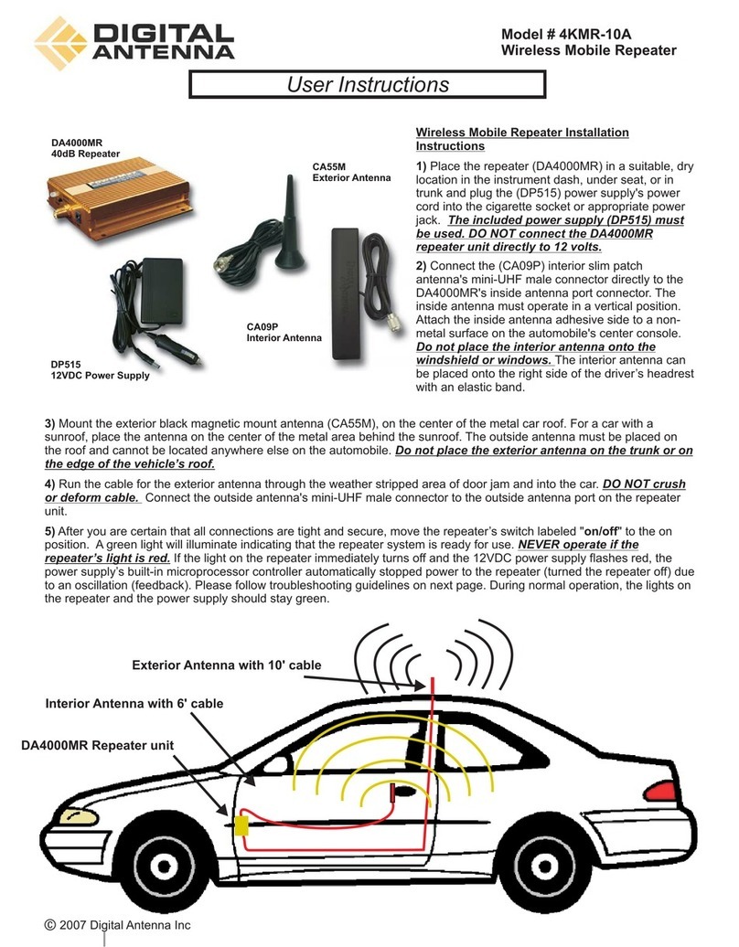
BK Radio DRH-01-100 User manual

DRH-01-100
Digital Repeater
Operator’s Manual
ON
OFF
TX RX
Programming
PN 7001-31019-200

Contents
FCC Requirements.........................................................................1
Contact Information....................................................................2
Connections and Control ...............................................................3
Basic Operation & Maintenance ....................................................4
Operation ...................................................................................4
Maintenance...............................................................................4
Installation & Site Requirements ....................................................4
Installation Requirements...........................................................4
Antenna Separation Considerations ..........................................5
Programmed Frequency Considerations ...................................6
Desktop or Rack Mounting Considerations................................6
Programming..................................................................................7
Required Equipment...................................................................7
Programming Channel Parameters............................................7
Programming Repeater Parameters ..........................................9
Optimizing Transmit Power ......................................................10
Contact Information......................................................................11

BK Radio 1
Introduction
This manual contains information concerning the operation procedures
for the BK Radio DRH-01-100 Repeater.
The DRH has been designed to meet the digital requirements of today’s
communications environment. Please take a moment to read the
information in this manual so you can get optimum performance from
your new radio.
When operating in digital mode the DRH passes crucial digital data
including P25 radio identication numbers, AES and DES encrypted
signals and P25 Emergency signals.
In addition the DRH is designed to pass the encryption key information
used in conjunction with BK Radio’s exclusive wireless tactical OTAR
option.
Check with your RELM/BK Radio dealer or communications ofcer
for information on the programmed functions of your repeater and
subscriber radios prior to operation.
Safety Precautions
• Do not operate the transmitter in close proximity to
blasting caps.
• Do not operate the radio in an explosive atmosphere
(petroleum fuels, solvents, dust, etc.).
FCC Requirements
This device complies with Part 15 of the FCC rules. Operation is subject
to the condition that this device does not cause harmful interference.
Your radio must be properly licensed by the Federal Communications
Commission prior to use. Your BK Radio dealer can assist you in
meeting these requirements. Your dealer or communications ofcer
will program each repeater with your authorized frequencies, signaling
codes, etc..

2 DRH-01-100 User’s Guide
Industry Canada Compliance
This Class B digital apparatus complies with Canadian ICES-003. Cet
appareil numerique de la classe B est conforme à la norme NMB-003
Canada.
RF Exposure Compliance and Control Guidelines
To control your exposure and ensure compliance with the occupational/
controlled environment exposure limits adhere to the following
procedures.
Warning: Maintain a separation distance from the antenna to a person(s)
of at least 5 ft. You, as the qualied end-user of this radio device must
control the exposure conditions of bystanders to ensure the minimum
separation distance (above) is maintained between the antenna and
nearby persons for satisfying RF Exposure compliance. The operation of
this transmitter must satisfy the requirements of 0ccupational /Controlled
Exposure Environment, for work-related use. Transmit only when
person(s) are at least the minimum distance from the properly installed,
externally mounted antenna.
For more information concerning radio frequency radiation visit these
websites:
http://www.fcc.gov/oet/rfsafety/rf-faqs.html
http://www.osha.gov/SLTC/radiofrequencyradiation
The AMBE® voice compression software included in this product
is protected by intellectual property rights including patent rights,
copyrights and trade secrets of Digital Voice Systems, Inc. The user
of this software is explicitly prohibited from attempting to decompile,
reverse engineer, or disassemble the object code, or in any other way
convert the object code into a human-readable form. This software is
licensed solely for use within this product. US Patent Nos. #6,912,495
B2, #5,870,405, #5,826,222, #5,754,974, #5,715,365, #5,701,390,
#5,649,050, #5,630,011, #5,581,656, #5,517,511, #5,491,772,
#5,247,579, #5,226,084, and #5,195,166.
CONTACT INFORMATION
For additional information on exposure requirements or other
information, visit website http://www.relm.com.

BK Radio 3
Connections and Control
Transmit Indicator
PC Programming JackPower Switch
ON
OFF
TX RX
Programming
Receive Indicator Front Cooling Fan
Front Panel
Transmit Antenna Connector Receiver Antenna Connector
AC Power Input PA Cooling Fan
DC Power Input
- +
Rear Panel

4 DRH-01-100 User’s Guide
Basic Operation & Maintenance
Operation
Prior to operation the DRH-01-100 must be loaded with authorized
frequencies and parameters by a qualied technician. (See “Programming”)
Ensure that all antenna and power cables are connected to the unit.
Operating the DRH-01-100 without the proper antenna could result
in damage to the repeater.
Turn the Power switch to the ON position.
The lighted switch indicates unit power. Transmit and receive LEDs
indicate current operating status.
To power-down turn the Power switch to the OFF position.
NOTE: If external DC supply is connected, the DC supply must be turned
off to power down the repeater.
Maintenance
Allow adequate clearance at both the front and back of the repeater to
provide air ow.
The front cooling fan lter should be kept clean and clear of debris and
should be periodically cleaned. To access the lter remove the fan shield
by pulling straight out.
Installation & Site Requirements
Installation Requirements
AC input - 110V, 60Hz
Rack Mount - Standard 19” rack mountable
Antenna Connections - N-Type
Use only manufacturer or dealer supplied antenna.
Optional DC Power Input
When AC power is interrupted, or not available, the DRH-01-100 can be
powered from a DC source.
DC Input requirements: 13.8V, 30 amp

BK Radio 5
Antenna Installation and Safe Operating Distances
Before installing the DRH-01-100 at the operating site, the following
details regarding desk or oor space, rack clearance and lightning
protection should be considered.
Antenna Minimum Safe Distance: 5 ft.
Antenna Gain: Zero dBd referenced to a dipole.
Antenna Mounting: The antenna supplied by the manufacturer or
radio dealer must not be mounted at a location such that during radio
transmission, any person or persons can come closer than the minimum
safe distance to the antenna.
To comply with current FCC RF Exposure limits, the antenna must be
installed at or exceeding the minimum safe distance shown above, and
in accordance with the requirements of the antenna manufacturer or
supplier.
Warning: You, as the qualied end-user of this radio device must control
the exposure conditions of bystanders to ensure the minimum separation
distance (above) is maintained between the antenna and nearby persons
for satisfying RF Exposure compliance. The operation of this transmitter
must satisfy the requirements of Occupational /Controlled Exposure
Environment, for work-related use. Transmit only when person(s) are
at least the minimum distance from the properly installed, externally
mounted antenna.
Antenna Separation Considerations
The physical separation between the receive and transmit antennas
is critical to system operation.
Receive
Antenna
Transmit
Antenna
Vertical
Separation
The required separation distance is dependant
on the operating frequencies and RF power
output. BK Radio recommends mounting both
receive and transmit antennas on a single
mast with the appropriate vertical separation.
The receive antenna should be mounted above
the transmit antenna.
For required distance refer to the chart below.
RF Power Minimum Separation
100 Watts 30 feet
50 Watts 25 feet
WARNING: Failure to maintain minimum antenna separation may
cause equipment damage.

6 DRH-01-100 User’s Guide
Programmed Frequency Considerations
For optimum operation, it is recommended the transmit and receive
frequency separation be at least 5 MHz (i.e. Rx:155.000 MHz/Tx:150.000
MHz). Failure to maintain adequate frequency and antenna separation
may result in receiver degradation and/or equipment damage.
Desktop or Rack Mounting Considerations
The DRH-01-100 is 19 inches (483 mm) wide (standard 19 inch rack
mountable), 5.5 inches high, 14.5 inches deep, and weighs 14.75 lb.
When mounting the DRH-01-100 Cabinet:
· Ensure that the unit is securely mounted.
· Ensure that the air vents are clear of obstructions.
· Ensure that there is adequate space for entry of external cables
(antenna and AC power cables) at the rear of the unit without the
need for small radius bends.
Lightning Protection
To minimize damage or injury, a complete system of lightning protection
and grounding connections is recommended.

BK Radio 7
Programming
Required Equipment
KAA0731 Programming Software
USB Programming Cable
Open the program
If prompted select P150 as the radio type.
Read the programmed information by clicking the Read icon
or select “Read All Data” from the Read menu.
Programming Channel Parameters
To access the DRH-01-100 channel parameters
click the “Zone #” folder in the left panel.
NOTE: The DRH-01-100 is capable of storing several channels of
information. Only one channel is used during normal operation. The
desired operating channel must be selected prior to operation. (See
Channel Selection in the Programming Repeater Parameters section of
this manual.)
Label
A channel label of up to thirteen characters can be assigned.
Receiver Freq
Valid receiver frequencies for the DRH-01-100 are from 136.000 MHz to
174.000 MHz in 1.25 kHz increments.
Mode
The Mode selection is available on units capable of digital or analog
operation. The DRH-01-100 operates in digital mode only. The Mode
selection is disabled.

8 DRH-01-100 User’s Guide
RX CG
The CTCSS Code Guard selection applies to models capable of operat-
ing in analog mode. The DRH-01-100 operates in digital mode only. The
receiver CTCSS Code Guard selection is disabled.
RX NAC
The receiver network access code is programmable in Hexadecimal from
$000 to $FFF or as decimal from 0000 to 4095.
Special RX NACs:
If $F7E (3966 decimal) is programmed as the RX NAC the repeater
will accept any incoming NAC and transmit the programmed TX NAC.
If $F7F (3967 decimal) is programmed as the RX NAC the repeater
will accept any incoming NAC and transmit the same NAC regardless
of the TX NAC programming.
TX CG
The CTCSS Code Guard selection applies to models capable of operat-
ing in analog mode. The DRH-01-100 operates in digital mode only. The
transmitter CTCSS Code Guard selection is disabled.
TX NAC
The transmitted network access code is programmable in Hexadecimal
from $000 to $FFF or as decimal from 0000 to 4095.
NOTE: $F7E (3966) and $F7F (3967) are reserved for receiver program-
ming only. (See above.)
BW
The Bandwidth selection applies only to analog channels. The DRH-
01-100 operates in digital mode only. The analog bandwidth selection is
disabled.

BK Radio 9
Programming Repeater Parameters
To access the DRH-01-100 repeater parameters
click the “Global” folder in the left panel.
Hang Times
Hang times hold the repeater in receive and/or transmit condition after
an incoming signal has dropped. This allows radio users to respond
without the repeater toggling to standby mode.
TX Hang Time (sec)
Select the desired time for the repeater to continue transmitting after
the incoming signal has stopped. 0 to 7.5 seconds.
RX Hang Time (sec)
Select the desired time for the repeater to keep the receiver open after
the incoming signal has stopped. 0 to 7.5 seconds.
Data Preamble (msec)
The Preamble is a signal that is sent when the repeater transmitter
transitions from idle to transmitting.
Programming a Data Preamble allows time for a receiving radio to
establish reception prior to receiving incoming signals, decreasing the
chance of missing information.
The Data Preamble can be programmed from 0 to 315 msec.
Channel Selection
Use the Zone and Channel drop boxes to select the DRH-01-100
operating channel.

10 DRH-01-100 User’s Guide
Optimizing Transmit Power
The DRH-01-100 is factory tuned to achieve a minimum of 100 Watts RF
output across the full band of the repeater (136 - 174 MHz). RF power
can be adjusted to a lower output on your operating frequency within
the parameters of the power amplier. The minimum power output of the
DRH-01-100 is approximately 50 Watts.
To access the DRH-01-100 transmit power
adjustment click the “Global” folder in the left
panel then select “Adjust Power”.
Adjusting the Power
Connect the Transmit Antenna Connector to an RF power meter capable
of reading a minimum of 250 Watts.
Enter the programmed transmit
frequency in the Tx Freq box.
Click the “Start Tx” button.1.
Record the Power DAC Setting.2.
Use the slider bar for course3.
adjustment and the arrows for
ne tuning to achieve the desired
power output.
Click the “Stop Tx” button to set 4.
the power.
NOTE: Changing the power settings at one frequency may cause
degraded performance at other frequencies. If the operating
frequency is changed the RF power must be readjusted for that
frequency.
To meet the minimum 100 watts specication the power DAC
should be reset to its original value prior to changing the operating
frequency.

BK Radio 11
Contact Information
RELM Wireless Corporation
7100 Technology Drive
West Melbourne, FL 32904
Corporate
Phone: (321) 984-1414
Toll Free:(800) 648-0947
Fax: (321) 984-0168
Email: Sa[email protected]m
Customer Service
Phone: (321) 984-1414
Toll Free:(800) 422-6281
Fax: (321) 953-7986
Email: Service@relm.com

12 DRH-01-100 User’s Guide
NOTES:

BK Radio 13

14 DRH-01-100 User’s Guide
PN 7001-31019-200
Revision 11-10
©2010 RELM Wireless Corporation
Table of contents
Popular Repeater manuals by other brands

Active SmartHome
Active SmartHome Repeater Installation and operation guide
Argent Cables
Argent Cables IR-KIT-X2 instruction manual

Danfuss
Danfuss SonoRepeat 210 installation guide
Greenspec
Greenspec AFP Nano Series quick start guide
HP
HP AdvanceStack J2610B Installation and reference guide
ECKELMANN
ECKELMANN KGLZCANREP Operating instruction
