Inovonics EN4204R User manual

2.5.20 357-05617-03 Rev A © Inovonics, 2020 - www.inovonics.com
EN4204R Four Zone Add-On Receiver with
Relay Outputs
Installation Instructions
1 Overview
The EN4204R four zone add-on receiver with relay outputs allows you to
add up to four transmitters to any application. With diversity reception and
advanced signal processing, Inovonics’ EchoStream technology is
designed to minimize dead spots in transmission areas.
The following add-on receivers are available from Inovonics:
* At least one relay must be used for faults to ensure the system is
supervised. More than one relay may be used, but that will deduct from the
number of alarm output relays.
1.1 Installing an Inovonics Security System
An EchoStream survey kit should be used to establish an EchoStream
system. The EchoStream survey kit measures the signal strength of high-
power repeater and sensor messages to help optimize your EchoStream
system.
Figure 1 Sample EchoStream system
The EchoStream survey kit provides you with two signal strength
measurements: signal level and signal margin.
Signal level
The signal level is the measurement of the overall decibel level of the
message.
Signal margin
The signal margin is the measurement of the decibel level of the message,
minus the decibel level of any interfering signals. Inovonics equipment
should be placed within a facility such that all end-devices produce signal
margin readings of at least 4 decibels.
Both the signal level and signal margin are measured in decibels. Because
signal strength and signal margin are measured on a logarithmic scale, the
difference between a decibel level of 3 (Weak) and a decibel level of 4
(Good) is a much larger difference than it would be on a linear scale.
Note: For more information about the EchoStream survey kit, see the
EN7017 Survey Kit and App Installation and Site Survey Instructions.
Caution: The EchoStream system should be tested regularly to ensure
operation. To test: place the system in test mode, activate an end device,
and ensure an appropriate response.
1.2 RF Signal Propagation
While wood, drywall and glass usually let the RF signals pass, some
materials may inhibit or attenuate radio frequency (RF) signal propagation
by blocking, reflecting, deflecting or absorbing RF signals.
Consider anything between transmitters and repeaters and/or the receiver.
Is there concrete and steel construction? Are there earthen berms or hills?
Are there a lot of trees? Devices should be mounted such that they are
least affected by these elements.
For best results, transmitters and repeaters should be mounted at the
optimal height to achieve line of sight to repeaters and/or the receiver.
Usually this means they will be mounted as high as possible.
Following are some typical obstacles to RF signal propagation:
1.3 Inovonics Wireless Contact Information
If you have any problems with this procedure, contact Inovonics Wireless
technical services:
• Phone: (800) 782-2709; (303) 939-9336.
Receiver Alarm Output
Relays Fault Relays Transmitters
Supported
EN4204R 4 1 4
EN4216MR 5 1* 16
EN4232MR 11 1* 32
Material Affect Recommendation
Metal construction,
including ductwork;
pipes; studs; stucco,
plaster or concrete with
wire mesh; satellite
dishes, metal-lined
rooms such as walk-in
coolers or freezers;
metal siding, safes, etc.
Can reflect,
absorb and/or
disrupt RF
signals.
Perform a site survey
using an Inovonics
wireless survey kit to
verify the RF signal is
acceptable, and, when
necessary, to
determine where to
locate repeaters.
Completely enclosed
metal boxes/enclosures.
Can restrict RF
signals.
Solar panels, cinder
block walls, windows
with built-in solar tinting.
Can absorb and/
or reflect RF
signals.
Vegetation. Can attenuate
RF signals. The
RF environment
can alter as
trees shed or
sprout leaves.
Add repeaters as
issues arise.
Automobile and truck
traffic.
Can disrupt RF
signals.
Mount Inovonics
devices at a height
sufficient to achieve
line of sight above
traffic.

2.5.20 357-05617-03 Rev A © Inovonics, 2020 - www.inovonics.com 2
1.4 EN4204R Four Zone Add-On Receiver with Relay
Outputs Front Panel
Figure 2 EN4204R receiver LEDs and buttons
1.5 EN4204R Four Zone Add-On Receiver with Relay
Outputs LEDs
Most of the LEDs and buttons perform different function depending on
which mode the the receiver is in. By default the LEDs are in operation
mode; to enter diagnostic mode, press the advance button.
Operation LEDs
Alarm LED: Lights when any transmitter is sending an alarm transmission.
Tamper Fault LED: Lights when any transmitter is sending a tamper
transmission.
Low Battery Fault LED: Lit when any transmitter has a low battery.
Inactive Fault LED: Lit when any transmitter is inactive.
Power LED: Lit when receiving power.
Transmitter Number LEDs: Lit when the transmitter is in alarm.
Decode LED: Flashes when any recognizable transmission is received.
This LED is only visible when the pry-out door or cover is removed.
Diagnostic LEDs
Alarm LED: Lights when the selected transmitter is sending an alarm
transmission.
Tamper Fault LED: Lights when the selected transmitter is sending a
tamper transmission.
Low Battery Fault LED: Lit when the selected transmitter has a low battery.
Inactive Fault LED: Lit when the selected transmitter is inactive.
Power LED: Lit when receiving power.
Transmitter Number LEDs: Shows status of the transmitter assigned to that
number when lit. Use the advance button to scroll through transmitters.
Advance Button: Scrolls through transmitters to display status.
Decode LED: Flashes when any recognizable transmission is received.
This LED is only visible when the pry-out door or cover is removed.
1.6 EN4204R Internal Components
Figure 3 EN4204R internal components
1.7 What’s in the Carton
• Two drywall anchors.
• Two mounting screws.
• Three housing screws.
• Two pieces double-sided mounting tape.
• One frequency band selection jumper.
2 Installation and Startup
2.1 Installation Notes
• These products are designed to be maintained by professional
security technicians.
• Products are tested for indoor use.
• Do not mount wireless smoke detectors, co detectors, initiating device
transmitters or repeaters to removable surfaces, such as ceiling tiles.
• All products should be manually tested weekly.
• The EN4204R must be installed within 30 m (98.5 ft) of control unit.
• Low power transmitters shall be limited to a single initiating device.
2.2 Connect Power Cabling
Caution: Incorrect connections may cause damage to the unit.
Before beginning startup, you will have to connect power to the receiver. To
connect power to the receiver:
1. Use a small screwdriver to press the housing release tab on the top or
bottom of the receiver; separate the housing.
2. Connect power cabling to the Power and GND connections.
• Power source should be 11-14 VDC. Power supply must be
unswitched, uninterrupted, and regulated.
• Use 18 - 22 gauge wire for all cabling, and ensure torque on the screw
terminals does not exceed 7 inch-pounds.
2.3 Select the Frequency Band
EchoStream products are able to use a range of radio frequencies, and are
shipped from Inovonics set for your geographic area.
• The jumper will be set on the two pins marked NZ to set the frequency
range to 921-928 MHz for New Zealand.
• The jumper will be set on the two pins marked AU to set the frequency
range to 915-928 MHz for Australia.
• The jumper will be removed to set the frequency band to 902-928
MHz for North America.
1. Ensure the frequency band is set for your geographic are.
2. If the frequency band is not set for your geographic area, place a
selection jumper on the appropriate frequency band selection pins to
select Australia or New Zealand, or remove it for North America.
Note: Only devices set for use in North America are configured for UL
installations.
3. If you have changed the frequency band and the device is powered on,
press the reset button to complete configuration.
3 Registering a Transmitter
3.1 Quick Setup
In many cases, the default settings are sufficient and the points don’t need
programming changes. To register transmitters without changing the
settings:
First Transmitter
1. Press the advance button one time to select the first point.
2. Press the program button four times to select the default programming
options.
3. The first point number will be flashing, indicating it is awaiting the
transmitter’s reset message; press the transmitter’s reset button.
Second Transmitter
1. Press the advance button two times to select the second point.
2. Press the program button four times to select the default programming
options.
3. The second point number will be flashing, indicating it is awaiting the
transmitter’s reset message; press the transmitter’s reset button.
Third Transmitter
1. Press the advance button three times to select the third point.
AAlarm LED BTamper Fault LED CLow Battery Fault LED
DInactive Fault LED EPower LED FTransmitter Number LEDs
GAdvance Button
AHousing release
tabs
BPower (11-14
VDC)
CGND connection
DOutput terminals EFault output FAdvance button
GReset button HReset input IJam output
JTamper output KProgram button LFrequency band selection
pins
MDecode LED
A
B
D
E
F
G
C
A
B
C
D
IJH
L
E
AA
M
F
K
G

2.5.20 357-05617-03 Rev A © Inovonics, 2020 - www.inovonics.com 3
2. Press the program button four times to select the default programming
options.
3. The third point number will be flashing, indicating it is awaiting the
transmitter’s reset message; press the transmitter’s reset button.
Fourth Transmitter
1. Press the advance button four times to select the fourth point.
2. Press the program button four times to select the default programming
options.
3. The fourth point number will be flashing, indicating it is awaiting the
transmitter’s reset message; press the transmitter’s reset button.
Note: After registering a transmitter, there is no need to exit programming
mode. The receiver is normal operation once the transmitter’s reset button
has been pressed.
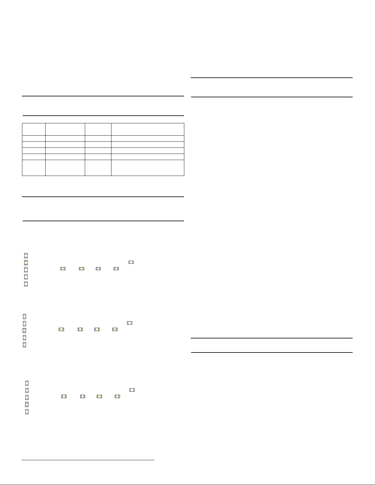
The default settings are:
3.2 Customize Transmitters
If the default settings are not sufficient, you will need to program the points
individually.
Note: If changing programming for a point that already has a transmitter
registered to it, there is no need to re-register the transmitter. Changes to
point programming are automatically assigned to the transmitter registered
to that point.
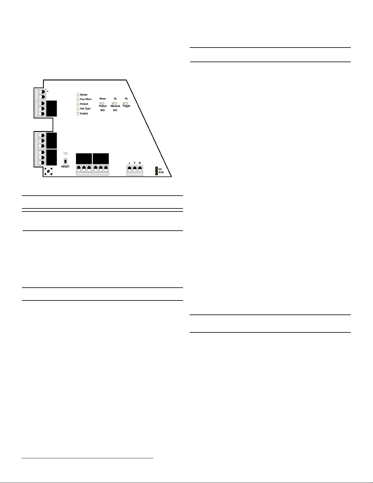
The following programming options available:
Supervision window
• None, 2h, 4h, or 96h. When you are choosing the supervision window,
the “Sup Wind” LED will light, along with the LED that indicates the
selected window.
Figure 4 Select the supervision window
Output (relay)
• 1, 2, 3, 4. When you are choosing the output, the “Output” LED will
light, along with the LED that indicates the selected output number.
Figure 5 Select the output number
Output type
• Follow, Moment, Toggle, Latch. When you are choosing the output,
the “Out Type” LED will light, along with the LED that indicates the
selected output type.
Figure 6 Select the output type
To program any of the four transmitter points:
1. Use the advance button to select any of the four transmitter points.
• Press the advance button one time to select the first point; the first
LED will light.
• Press the advance button two times to select the second point; the
second LED will light.
• Press the advance button three times to select the third point; the third
LED will light.
• Press the advance button four times to select the fourth point; the
fourth LED will light.
2. Press the program button to begin programming the point.
Note: The program button should be pressed within a few seconds of
selecting the point number. If not, the point number will not be lit, and you
will need to select it again.
• If no transmitter has been registered to the chosen point, the receiver
advances to the supervision window option.
• If a transmitter has already been registered to the chosen point, the
delete LED lights. Press advance to delete the point and return to
normal operation; press program to advance to the supervision
window option.
3. Use the advance button to choose a supervision window of None, 2h,
4h and 96h (Fig. 4).
• Press the advance button one time to select none.
• Press the advance button two times to select two hours.
• Press the advance button three times to select four hours.
• Press the advance button four times to select 96 hours.
When you have selected the supervision window, press program to
complete and advance to the output option.
4. Use the advance button to select the output number (Fig. 5).
• Press the advance button one time to select the first output.
• Press the advance button two times to select the second output.
• Press the advance button three times to select the third output.
• Press the advance button four times to select the fourth output.
When you have selected the output number, press program to complete
and advance to output type option
5. Use the advance button to select the output type (Fig. 6),
• Press the advance button one time to select follower. In follower the
output reflects the transmitter’s alarm status.
• Press the advance button two times to select momentary. In
momentary the output turns on for seven seconds, then turns off,
regardless of the device status.
• Press the advance button three times to select toggle. In toggle the
output changes state each time the device sends a new activation. A
minimum of four seconds must elapse before the output can send a
new activation.
• Press the advance button four times to select latching. In latching the
output turns on when activated and remains on until the receiver is
reset.
When you have selected the output type, press program to complete
and advance to the switch type option.
6. All the option LEDs will light and the point you’ve just programmed will
flash. If you wish to register a transmitter to the point you’ve just
programmed, press the transmitter’s reset button; otherwise, press
program to save programming changes without registering a
transmitter.
Note: The registration is not complete until all LEDs turn off and the point
number lights.
All of the alert LEDs will turn off when the receiver has received the
transmitter’s registration message, and the point number LED will light for
two seconds. This indicates the receiver has received the transmitter’s
registration message. If this does not occur, press reset on the transmitter
again.
3.3 Connect Input/Output Cabling
The tamper output, jam output and reset input are open collectors, not dry
contacts.
1. Connect cabling to the tamper output. Must be configured for UL
installations.
• The tamper output is a normally open (N/O) open collector output that
reports receiver case tamper to an external device.
2. Connect cabling to the jam output. Must be configured for UL
installations.
• The jam output is a normally closed (N/C) open collector output that
opens when noise thresholds on all receive channels remain above a
predetermined value for 10 seconds. The jam output is set to the
follower output type.
Point Supervision
Window
Output Type
1 4 hours 1 Follow
2 4 hours 2 Follow
3 4 hours 3 Follow
4 4 hours 4 Follow
F N/A Fault Inactive is set to follow; low
battery and tamper are set to
latching.
Delete
Out Type
Output
Sup Wind
Switch
F
Toggle
4h
Latch
96h
Follow
None
N/O
Moment
2h
N/C
12
34
Delete
Out Type
Output
Sup Wind
Switch
F
Toggle
4h
Latch
96h
Follow
None
N/O
Moment
2h
N/C
12
34
Delete
Out Type
Output
Sup Wind
Switch
F
Toggle
4h
Latch
96h
Follow
None
N/O
Moment
2h
N/C
12
34

2.5.20 357-05617-03 Rev A © Inovonics, 2020 - www.inovonics.com 4
3. Connect a momentary switch to the reset input and ground (Figure 7,
“EN4204R terminals”). Must be configured for UL installations.
• The reset input circuit permits installation of a remote momentary
normally open (N/O) switch to clear faults, unlatch outputs, and reset
the receiver to a normal state.
4. Connect cabling to the output terminals. Must be configured for UL
installations.
• The EN4204R provides five Form-C relays.
Figure 7 EN4204R terminals
3.4 Mount the Receiver
Caution: Mount the receiver in a location removed from metal. Metal
objects (duct work, wire mesh screens, boxes) will reduce RF range.
Note: For UL listed systems containing a UL hold-up switch, the EN4204R
must be located within three feet of a system keypad in a location out of
sight from the protected premise.
1. Use the provided anchors and screws to mount the receiver in a
location accessible for future maintenance, making sure the housing is
flush with the wall and the back tamper switch is actuated.
2. After all transmitters have been registered, perform a walk test,
activating each transmitter assigned to the receiver and ensuring a
good signal.
4 Return to Factory Configuration
The EN4204R four zone add-on receiver with relay outputs can be returned
to factory defaults using the following.
Caution: This procedure will erase all programmed point and output
information.
To restore the factory configuration defaults to the receiver:
1. Hold down the reset and advance buttons.
2. With the buttons held down, cycle power.
5 Specifications
UL compatible repeater, transmitters: EN5040-T, EN1215EOL,
EN1215WEOL, EN1223D, EN1235SF, EN1235DF, EN1244, EN1245,
EN1249, EN1261HT.
Housing: 6.38" x 3.60" x 1.10" (162 mm x 92 mm x 28 mm).
Operating environment: 32°- 140°F (0°- 60°C), 90% relative humidity, non-
condensing.
Power requirement: 11 - 14 VDC; 400 mA.
Current consumption: Approx. ~400 mA max with all five relays energized.
Output specifications: Form C relay 1A @ 28 VDC, 0.5A @ 30 VAC
resistive load; N/O receiver case tamper contact closure, N/C receiver jam
output indication.
Input specifications: A low is less than .5 V; a high is greater than 2.5 V.
Reset input: Contact closure, momentary low.
Receiver type: Frequency hopping spread spectrum.
Operating frequency: 915-928 MHz (Australia), 921-928 MHz (New
Zealand), 902-928 MHz (USA).
Number of points/transmitters: Four.
Number of alarm outputs: Four Form C relay outputs.
Number of fault outputs: One Form C relay output.
UL listings: UL 365, UL 636, UL 985, UL 1023, ULC/ORD-C1023-74, UL
1610, UL 1076.
Note: Inovonics supports recycling and reuse whenever possible. Please
recycle these parts using a certified electronics recycler.
6 UL Requirements
• Due to the trouble output being shared by all transmitters, this receiver
must be set up and programmed as a commercial and residential
burglary receiver.
• The control panel must be programmed to indicate an alarm if the
system is in an armed condition and an RF jamming signal occurs at
the receiver.
• The receiver tamper and transmitter tamper cannot be combined in
one loop.
• The control unit providing input power to the receiver must not have a
range outside of 11-14 VDC.
7 Television and Radio Interference
This equipment has been tested and found to comply with the limits for a
Class B digital device, pursuant to Part 15 of the FCC Rules. These limits
are designed to provide reasonable protection against harmful interference
in a residential installation. This equipment generates, uses and can
radiate radio frequency energy and, if not installed and used in accordance
with the instructions, may cause harmful interference to radio
communications. However, there is no guarantee that interference will not
occur in a particular installation. If this equipment does cause harmful
interference to radio or television reception, which can be determined by
turning the equipment off and on, the user is encouraged to try to correct
the interference by one or more of the following measures:
• Reorient or relocate the receiving antenna.
• Increase the separation between the equipment and receiver.
• Connect the equipment into an outlet on a circuit different from that to
which the receiver is connected.
• Consult the dealer or an experienced radio/TV technician for help.
8 FCC Part 15 and Innovation, Science and
Economic Development Canada (ISED)
Compliance
This device complies with part 15 of the FCC Rules, and ISED license-
exempt RSS standard(s). Operation is subject to the following two
conditions: (1) this device may not cause interference, and (2) this device
must accept any interference that may cause undesired operation of the
device.
Le présent appareil est conforme aux CNR Innovation, Sciences et
Développement économique Canada applicables aux appareils radio
exempts de licence. L'exploitation est autorisée aux deux conditions
suivantes: (1) l'appareil ne doit pas produire de brouillage, et (2) l'utilisateur
de l'appareil doit accepter tout brouillage radioélectrique subi, même si le
brouillage est susceptible d'en compromettre le fonctionnement.
Caution: Changes or modifications not expressly approved by the party
responsible for compliance could void the user's authority to operate the
equipment.
Vs
Jam output
Ground
Tamp er
Reset input
Caution: Incorrect
connections may cause
damage to the unit
NC
COM 1
NO
NC
COM 2
NO
NC
COM 3
NO
NC
COM 4
NO
NC
FAULT
NO

2.5.20 357-05617-03 Rev A © Inovonics, 2020 - www.inovonics.com 5
9 Radiation Exposure Limits
9.1 FCC
This equipment complies with FCC radiation exposure limits set forth for an
uncontrolled environment. In order to avoid the possibility of exceeding the
FCC radio frequency exposure limits, human proximity to the antenna shall
not be less than 20 cm during normal operation and must not be co-located
or operating in conjunction with any other antenna or transmitter.
9.2 ISED
This equipment complies with ISED RSS-102 radiation exposure limits set
forth for an uncontrolled environment. This transmitter must be installed to
provide a separation distance of at least 20 cm from all persons and must
not be co-located or operating in conjunction with any other antenna or
transmitter.
Cet équipement est conforme avec ISED RSS-102 des limites d'exposition
aux rayonnements définies pour un environnement non contrôlé. Cet
émetteur doit être installé à au moins 20 cm de toute personne et ne doit
pas être colocalisé ou fonctionner en association avec une autre antenne
ou émetteur.
Table of contents
Other Inovonics Repeater manuals
Popular Repeater manuals by other brands

Sercomm
Sercomm Sercomm SZS user guide

Omega Technology
Omega Technology OWLR325W manual

Peninsula Engineering Solutions
Peninsula Engineering Solutions RF-2000E manual

DAVIS
DAVIS Wireless Repeater 7614 installation manual

Stahl
Stahl 9163 Series operating instructions

Define Instruments
Define Instruments P2P-R General information