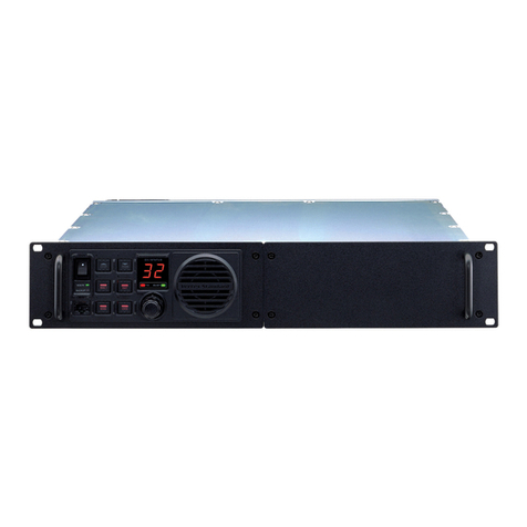
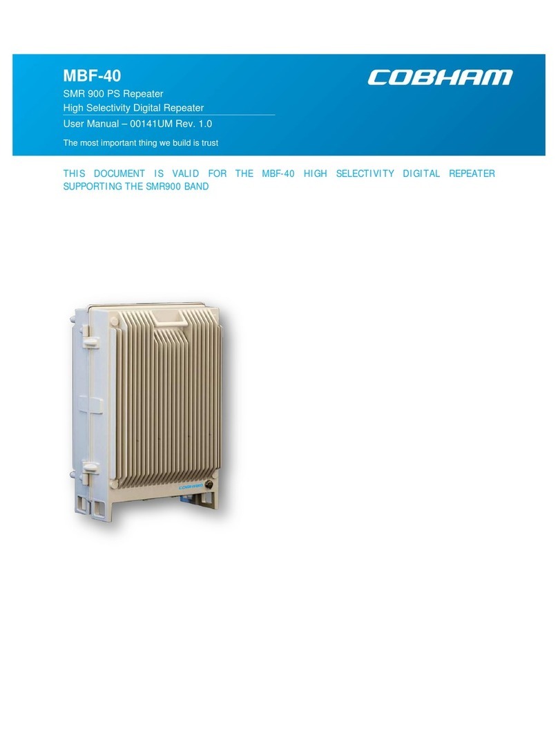
Watkins-Johnson Company R1910 User manual

W
Watkins-Johnson Company
Repeater
Manual
WATKINS-JOHNSON COMPANY
3333 Hillview Avenue
Palo Alto, CA 94304-1223

Watkins-Johnson Company
PCS Repeater
Manual
“This drawing, print, or document and subject matter disclosed
herein are proprietary items to which Watkins-Johnson Company
retains the exclusive right of dissemination, reproduction,
manufacture and sale. This drawing, print or document is
submitted in confidence for consideration by the designated
recipient or intended using organization alone unless permission
for further disclosure is expressly granted in writing.”
09/99
WATKINS-JOHNSON COMPANY
3333 Hillview Avenue
Palo Alto, CA 94304-1223
(800) 951-4401
Internet: http://www.wj.com

Repeater Table of Contents
i
Table of Contents
Section Topic Page
Chapter 1 General Information and Safety Precautions 1-1
Introduction 1-1
Specifications 1-6
Safety Considerations 1-10
Description 1-10
Mechanical 1-11
Environmental Conditions 1-12
Chapter 2 Installation 2-1
Introduction 2-1
Unpacking and Inspection 2-1
Preparation For Use 2-1
Pre-Installation Information 2-2
Installation Information 2-3
Repeater Initial Turn-On Procedure 2-6
Setup 2-6
Isolation and Alignment Procedure 2-7
Multicarrier & FCC Spurious 2-9
Connectors 2-10
Storage 2-11
Packing for Reshipment or Storage 2-11
Chapter 3 Operation 3-1
Introduction 3-1
Operating Instructions 3-1
Chapter 4 Scheduled Maintenance 4-1
Introduction 4-1
Scheduled Maintenance Action Index 4-1
Equipment Required 4-1
Preventive Maintenance Procedures 4-1
General Maintenance 4-2
Alignment 4-2
Repair 4-2
Chapter 5 Drawings 5-1
R1910 Mounting 5-1
R1920 Mounting Plate 5-2
R1920 and BB42 Mounting 5-3
R1920 Electrical and System Configuration 5-4

Repeater General Information and Safety Precautions
1-1
CHAPTER 1
GENERAL INFORMATION AND SAFETY PRECAUTIONS
1-1 INTRODUCTION
This manual provides information pertaining to the installation, operation, and maintenance of the
Watkins-Johnson Repeaters, shown in Figure 1-1. The model number represents the type of repeater.
This manual covers the following types of repeaters. The model numbers and letters are defined in
the following example.
Example: R1910CAD-1M is a PCS indoor repeater, with CDMA modulation, using frequency
bands A and D, 1.25mhz bandwidth, with a modem.
Repeater Model Number Repeater Description
R1910 PCS Inbuilding Repeater
R1920 PCS High Power Repeater
R1930 PCS Medium Power Repeater
R1940 PCS Low Power Repeater
R810 Cellular Inbuilding Repeater
R820 Cellular High Power Repeater
Modulation PCS
Frequency
Band
Bandwidth Interface
Option
CDMA = C
TDMA = T
GSM = G
AD*
BE*
FC*
-1 = 1.25 MHz
-2 = 0.20 MHz
-3 = 5.00 MHz
-4 = 15.0 MHz
-5 = 1.00 MHz
-6 = 4.50 MHz
-7 = 7.00 MHz
M= modem
* Specifies dual bands.
** The R810 and R820 cover the entire A or B band

Repeater General Information and Safety Precautions
1-2
This manual is divided into five chapters, the first four covering a particular topic for the operation
and maintenance of the unit. Chapter 5 includes drawings to assist in mounting WJ repeaters. The
topics are as follows:
Chapter Topic
1General Information and Safety Precautions
2Installation
3Operation
4Scheduled Maintenance
5Drawings

Repeater General Information and Safety Precautions
1-3
Figure 1-1. R1910 and R810 Repeater

Repeater General Information and Safety Precautions
1-4
Figure 1-2. R1920/30/40, R820 Repeater

Repeater General Information and Safety Precautions
1-5
Chapter 1 provides a general description of the Repeater and summarizes the electrical, mechanical,
and environmental characteristics. It also provides a tabular listing of the Repeater performance
specifications. Safety precautions to be observed while operating or servicing the unit are also
explained.
Chapter 2 provides instructions for the initial inspection and installation of the Repeater. It describes
the purpose and function of all I/O connectors, provides initial start-up instructions, and provides
installation verification tests.
Chapter 3 describes the purpose and function of all remote controls and status indicators and
explains how to operate the unit.
Chapter 4 provides a scheduled maintenance action index and describes maintenance procedures that
should be performed on a regular basis, such as cleaning and inspection.
Chapter 5 provides drawings useful when mounting a WJ repeater to a structure.

Repeater General Information and Safety Precautions
1-6
1-2 SPECIFICATIONS
Table 1-1. R1910 Specification
DESCRIPTION SPECIFICATION
Frequency Band AD, BE, or FC
Output Power 100 mWatts CDMA
500 mWatts TDMA
500 mWatts PCS-1900 (GSM)
Filter Bandwidth 1.25 MHz CDMA (other filters available)
200KHz TDMA (other filters available)
200 kHz GSM-1900 (other filters available)
Noise Figure 4 dB Typical
Maximum Input without damage -10 dBm
Input Impedance 50 ohms
Gain Range 40 dB to 70 dB or 65 dB to 95 dB
Gain Steps 2 dB
Signal Delay 5 usec max
Power 115 / 230 VAC, 60 / 50 Hz, 1.6 / 0.8 Amps
Alarms & Status Synthesizer, Amplifiers, Power Amplifier, Output Power, Oscillation
Interface RS-232 (modem optional)
Control Gain, Channel frequency, Auto Level Control, and Tracking Offset
Cooling Convection
Temperature Operating: -10 to +45ºC
Storage: -40 to +85ºC
Size 12” x 16” x 3”
Weight 19 lbs.
Weather Resistance NEMA 12
Connectors
RF
Control
AC Power
Type N
9 pin Dsub Female
NEMA Type 5-ISP

Repeater General Information and Safety Precautions
1-7
Table 1-2. R1920 Specification
DESCRIPTION SPECIFICATION
Frequency Band AD, BE, or FC
Output Power 8 Watts CDMA
10 Watts TDMA
15 Watts GSM-1900
Filter Bandwidth 1.25 MHz CDMA (other filters available)
200 kHz TDMA (other filters available)
200 kHz GSM-1900 (other filters available)
Noise Figure 4 dB Typical
Maximum Input without damage -10 dBm
Input Impedance 50 ohms
Gain Range 65 dB to 95 dB
Gain Steps 2 dB
Signal Delay 5 usec max
Power 115 / 230 VAC, 60 / 50 Hz, 4 / 2 Amps
Alarms & Status Synthesizer, Amplifiers, Power Amplifier, Output Power, Oscillation
Interface RS-232 and modem
Control Gain, Channel frequency, Auto Level Control, and Tracking Offset
Cooling Convection
Temperature Operating: -40 to +50ºC
Storage: -40 to +85ºC
Size 14.5” x 16” x 9”
Weight 55 lbs.
Weather Resistance NEMA 4X
Connectors
RF
Control
AC Power
Battery
Type N
9 pin D-sub, 3 pin circular(see section 2 for pinout information)
3 pin Mini-circular(see section 2 for pinout information)
6 pin Mini-circular

Repeater General Information and Safety Precautions
1-8
Table 1-3. R1930 Specification
DESCRIPTION SPECIFICATION
Frequency Band AD, BE, or FC
Output Power 4 Watts CDMA
Filter Bandwidth 1.25 MHz CDMA (other filters available)
Noise Figure 4 dB Typical
Maximum Input without damage -10 dBm
Input Impedance 50 ohms
Gain Range 65 dB to 95 dB
Gain Steps 2 dB
Signal Delay 5 usec max
Power 115 / 230 VAC, 60 / 50 Hz, 4 / 2 Amps
Alarms & Status Synthesizer, Amplifiers, Power Amplifier, Output Power, Oscillation
Interface RS-232 and modem
Control Gain, Channel frequency, Auto Level Control, and Tracking Offset
Cooling Convection
Temperature Operating: -40 to +50ºC
Storage: -40 to +85ºC
Size 14.5” x 16” x 9”
Weight 55 lbs.
Weather Resistance NEMA 4X
Connectors
RF
Control
AC Power
Battery
Type N
9 pin D-sub, 3 pin circular(see section 2 for pinout information)
3 pin Mini-circular(see section 2 for pinout information)
6 pin Mini-circular

Repeater General Information and Safety Precautions
1-9
Table 1-4. R1940 Specification
DESCRIPTION SPECIFICATION
Frequency Band AD, BE, or FC
Output Power 2 Watts CDMA
Filter Bandwidth 1.25 MHz CDMA (other filters available)
Noise Figure 4 dB Typical
Maximum Input without damage -10 dBm
Input Impedance 50 ohms
Gain Range 65 dB to 95 dB
Gain Steps 2 dB
Signal Delay 5 usec max
Power 115 / 230 VAC, 60 / 50 Hz, 4 / 2 Amps
Alarms & Status Synthesizer, Amplifiers, Power Amplifier, Output Power, Oscillation
Interface RS-232 and modem
Control Gain, Channel frequency, Auto Level Control, and Tracking Offset
Cooling Convection
Temperature Operating: -40 to +50ºC
Storage: -40 to +85ºC
Size 14.5” x 16” x 9”
Weight 55 lbs.
Weather Resistance NEMA 4X
Connectors
RF
Control
AC Power
Battery
Type N
9 pin D-sub, 3 pin circular(see section 2 for pinout information)
3 pin Mini-circular(see section 2 for pinout information)
6 pin Mini-circular

Repeater General Information and Safety Precautions
1-10
Table 1-1. R810 Specification
DESCRIPTION SPECIFICATION
Frequency Band A or B
Output Power 100 mWatts
Filter Bandwidth Entire A or B band
Noise Figure 4 dB Typical
Maximum Input without damage -10 dBm
Input Impedance 50 ohms
Gain Range 40 dB to 70 dB
Gain Steps 2 dB
Signal Delay 5 usec max
Power 115 / 230 VAC, 60 / 50 Hz, 1.6 / 0.8 Amps
Alarms & Status Synthesizer, Amplifiers, Power Amplifier, Output Power, Oscillation
Interface RS-232 (modem optional)
Control Gain, Channel frequency, Auto Level Control, and Tracking Offset
Cooling Convection
Temperature Operating: -10 to +45ºC
Storage: -40 to +85ºC
Size 12” x 16” x 4”
Weight 19 lbs.
Weather Resistance NEMA 12
Connectors
RF
Control
AC Power
Type N
9 pin Dsub Female
NEMA Type 5-ISP

Repeater General Information and Safety Precautions
1-11
Table 1-1. R820 Specification
DESCRIPTION SPECIFICATION
Frequency Band A or B
Output Power 5 Watts
Filter Bandwidth Entire A or B band
Noise Figure 4 dB Typical
Maximum Input without damage -10 dBm
Input Impedance 50 ohms
Gain Range 55 dB to 85 dB
Gain Steps 2 dB
Signal Delay 5 usec max
Power 115 / 230 VAC, 60 / 50 Hz, 4 / 2 Amps
Alarms & Status Synthesizer, Amplifiers, Power Amplifier, Output Power, Oscillation
Interface RS-232 (modem optional)
Control Gain, Channel frequency, Auto Level Control, and Tracking Offset
Cooling Convection
Temperature Operating: -10 to +45ºC
Storage: -40 to +85ºC
Size 14.5” x 16” x 10”
Weight 55 lbs.
Weather Resistance NEMA 12
Connectors
RF
Control
AC Power
Battery
Type N
9 pin D-sub, 3 pin circular(see section 2 for pinout information)
3 pin Mini-circular(see section 2 for pinout information)
6 pin Mini-circular

Repeater General Information and Safety Precautions
1-12
NOTE:
This equipment has been tested and found to comply with the
limits for a Class A digital device, pursuant to Part 15 of the FCC
Rules. These limits are designed to provide reasonable protection
against harmful interference when the equipment is operated in a
commercial environment. This equipment generates, uses, and
can radiate radio frequency energy and, if not installed and used
in accordance with the instruction manual, may cause harmful
interference to radio communications. Operation of this
equipment in a residential area is likely to cause harmful
interference in which case the user will be required to correct the
interference at his own expense.
__________
CAUTION:
Changes or modifications not expressly approved by the
manufacturer responsible for compliance could void user’s
authority to operate the equipment.
1-3 SAFETY CONSIDERATIONS
__________
WARNING
To prevent personal injury, observe all safety precautions and
warnings stated on the instrument and in this manual.
Specific warnings, cautions, and instructions are placed wherever applicable throughout this manual.
These precautions must be observed during all phases of operation, service, and repair of this unit.
Failure to comply with these precautions or with specific warnings elsewhere in this manual violates
safety standard of design, manufacture, and intended use of this instrument.
1-4 DESCRIPTION
The WJ-R19XX Repeaters are used to extend the coverage of a PCS basestation. For example,
inside buildings that do not allow sufficient signal strength from the basestation, there exists a hole in
the coverage for wireless service. The WJ-R1910 is designed to solve that problem.
Likewise, tall buildings in a metropolitan area, or mountains in a more rural area, can reduce
basestation signal strength such that pockets of unusable areas develop. The WJ-R1920/30/40 is
designed to solve that problem.

Repeater General Information and Safety Precautions
1-13
The repeater receives the basestation signal via an external antenna see Figure 1-3. This signal is
amplified and filtered by the repeater and ultimately retransmitted via a second antenna. The entire
process is duplicated for the reverse path where the handset signal is amplified and filtered and
retransmitted to the basestation. This technique provides PCS coverage inside buildings or in
outside areas that previously did not have sufficient signal strength.
Outside Building Inside Building
Lightning Arrestor
Figure 1-3. R1910/R810 Typical Usage
1-4.1 Remote Control
Remote control and status reporting of the repeater is provided either through an RS-232 serial
interface or via modem using a standard POTS line. Either interface permits the control of channel
frequency and gain, and can provide unit alarm status.
1-4.2 Prime Power
The R1910 and R810 is equipped with a power supply with an input of 115 / 230 VAC, 60 / 50 Hz,
1.6 / 0.8 Amps. Power consumption is approximately 65 Watts.
The R1920/30/40 and R820 is equipped with a power supply with an input of 115 / 230 VAC, 60 /
50 Hz, 4 / 2 Amps with an optional +24VDC/Battery input. Power consumption is approximately
250 Watts.
1-5 MECHANICAL
The R1910 and R810 are a 12 x 16 x 3 wall mount unit. Four mounting feet are provided for
installation. The unit is designed to withstand a NEMA 12 type environment.
RepeaterRepeaterRepeaterRepeater
Server Antenna
Donor Antenna
WJ R1910

Repeater General Information and Safety Precautions
1-14
The R1920/30/40 and R820 a 12 x 16 x 3 tower mount unit. A mounting bracket is provided for
installation. The unit is designed to withstand a NEMA 4X type environment.
1-6 ENVIRONMENTAL CONDITIONS
1-6.1 Non-operating Environmental Conditions
The Repeater will survive strains, jars, vibrations, or other conditions incident to normal
maintenance, transportation, and handling. Temperature ranges can vary between -40°C and
+85°C with humidity up to 95% non-condensing.
1-6.2 Operating Environmental Conditions
The R1910 and R810 can be installed and operated in a commercial environment with temperatures
varying between -10°C and 45°C.
The R1920/30/40 and R820 can be installed and operated in an outdoor environment with
temperatures varying between -40°C and 50°C.
1-6.3 Transportability
The Repeater can be transported by commercial land carriers or pressurized commercial air carriers
without special handling provisions.

Repeater Installation
2-1
CHAPTER 2
INSTALLATION
2-1 INTRODUCTION
This chapter provides information for the installation, setup and alignment of the R19X0 PCS
Repeater. The information consists of procedures for unpacking, inspection, and preparation for
reshipment or storage, and description of unit connectors. It also provides initial start-up
instructions and installation verification tests.
2-2 UNPACKING AND INSPECTION
Examine the shipping carton for damage before unpacking the unit. If the shipping carton is
damaged, try to have the carrier's agent present when the equipment is unpacked. If carrier's agent is
not available, retain the shipping cartons and padding material for the carrier's inspection if damage
to the equipment is evident after it has been unpacked.
Verify that the equipment is complete, as listed on the packing slip. Contact Watkins-Johnson
Company, Palo Alto, California, or your local Watkins-Johnson representative with details of any
shortage.
The unit was thoroughly inspected and factory adjusted for optimum performance prior to shipment.
Thus, it is ready for use upon receipt. After unpacking and checking contents against the packing
slip, visually inspect all exterior surfaces for dents and scratches. If external damage is visible,
contact Watkins-Johnson Company.
2-3 PREPARATION FOR USE
2-3.1 Power Requirements
The R1910 is equipped with a power supply that accepts 115 / 230 VAC 1.6 / 0.8 Amps @ 60 /
50 Hz single phase. Power consumption of the R1910 is approximately 65 Watts. The R1920/30/40
is equipped with a power supply that accepts 115/230 VAC 4 / 2 Amps @ 50/60 Hz, with optional
+24VDC/Battery input. Power consumption is approximately 250 Watts.
___________
WARNING
Removing or defeating the ground prong on the power cord may
present a lethal shock hazard. Do not use an ac two-to-three wire
adapter plug with this unit.
The R1910 power cord has a 3-conductor grounded plug complying with the National Electric Code
(NEMA Type 5-15P) for 110 VAC operation. For the R1920/30/40, or for operation at other
voltages, contact Watkins-Johnson Company or a qualified service technician.

Repeater Installation
2-2
2-3.2 Software Installation
The repeater control application provided on 3.5” floppy disks or CD-ROM, runs on any Personal
Computer (PC) running Microsoft Windows 95, 98, or NT 4.0 or higher. The computer must also
have one of two serial communications ports available for use, COM 1 or COM 2. To install the
application, insert disk 1 into floppy disk drive A: and from the Start menu select Run and enter
“a:\setup” in the text box of the Run window. Click the OK button and follow the instructions given.
2-3.3 Operating Environment
Environmental conditions during operation should normally be limited as follows:
R1910:
a. Maximum humidity: 95%
b. Temperature range: -10°C to +45°C.
R1920/30/40:
a. Temperature range: -40°C to +50°C.
2-4 PRE-INSTALLATION INFORMATION
2-4.1 R1910
You will need to know some basic information before beginning the R1910 installation. Write this
information down, you will need it later on.
1. Base station location and Channel number to be repeated.
2. Reverse Tracking offset in dB (Optional).
3. Location where the Donor antenna is to be installed.
4. Location where the Server antenna is to be installed.
5. Phone number of modem line. (Optional)
6. Location where the R1910 is to be installed (Lat/Long).
2-4.2 R1920/30/40
You will need to know some basic information before beginning the R1920/30/40 installation. Write
this information down, you will need it later on.
1. Base station location and Channel number to be repeated.
2. Reverse Tracking offset in dB (Optional).
3. Location where the Donor antenna is to be installed.
4. Location where the Server antenna is to be installed.
5Phone number of modem line.
6. Location where the R1920 is to be installed (Lat/Long).
2-5 INSTALLATION INFORMATION

Repeater Installation
2-3
2-5.1 Donor Antenna Installation
The Donor antenna will be mounted outside. The antenna should be installed so that it is in line-of-
sight of the base station and is pointed directly at it. If there is an arrow or polarity marking indicated
on the antenna, ensure that it is pointing up. Be sure that the antenna or mast is properly grounded
with a grounding strap. For clearances, grounding and mounting requirements please refer to Article
810 of NEC handbook.
For the R1910, determine where the RF cable will enter building and drill hole if necessary. A
lightning suppressor is highly recommended. Install suppressor inside building where cable entry is.
Attach grounding strap to lightning suppressor. Measure distance between antenna connection and
lightning suppressor. Be sure to add some length for drip loop and cut cable. When routing cable, be
careful not to kink, cut or damage cable. Install connectors on cable using the appropriate tool and
connect to antenna and lightning suppressor connector labeled “Surge”.
2-5.2 Server Antenna Installation
The Server antenna should be located in an open area free from metallic obstruction if possible and in
a location such that mobiles will always be at least 2 meters away. Mount antenna and route cable
from antenna to R1910 location. When routing cable, be careful not to kink, cut or damage cable. No
lightning suppression is needed if the antenna is indoors or under an overhang. Install connector using
the appropriate tool and connect to antenna. For clearances, grounding and mounting requirements
please refer to Article 810 of NEC handbook.
2-5.3 Proper Weather Sealing of RF Connectors.
It is important to properly weather-seal mated connectors against water migration into the RF
connectors and coaxial cables. Water migration into the jumper cable will cause considerable signal
attenuation and poor return loss. There are several commercial products available for this purpose.
The following guidelines should be followed when weather sealing antennas:
•Make sure the connector and cable to be sealed are clean and dry.
•Wrap the sealant to ensure a continuous seal around the connector body and the coaxial cable. If
you pre-wrap the connection with vinyl tape, be careful to leave extra space for the sealant to
contact the connector body and the cable directly.
•After the entire connection has been covered with the manufacturer's recommended amount of
sealant, mold and form the sealant by hand to ensure good contact and to force out trapped air.
•Carefully inspect the seal to make certain that all joints and openings are covered and sealed.
•Wrap the sealant with UV stabilized vinyl tape for additional protection.
2-5.4 R1910 Installation
This manual suits for next models
5
Table of contents


