4 Design
BRSS-RK-RTR and BRSS-RK-RTR ver.1 design and markup scheme
are shown in Figures 1 and 2 correspondingly.
WIRELESS ZONE EXTENSION
REPEATER
«Ladoga BRSS-RK-RTR»
1 General Information
Wireless zone extension repeater «Ladoga BRSS-RK-RTR», «Ladoga
BRSS-RK-RTR» ver. 1 (hereinafter, the BRSS-RK-RTR) are designed
for connection of terminal devices (hereinafter, TD) located in
poor-reception zone to «Ladoga-BRSS-RK-485» ver.1 and «Ladoga-
BRSS-RK-485»ver. 2 and to others external devices (hereinafter,
Coordinator), supporting wireless two-way communication by the
«RIELTA-Contact-R» protocol ver. 6 and higher.
BRSS-RK-RTR retransmits received information by the «RIELTA-
Contact-R» protocol ver. 6 and higher.
Total number of TD conneced to BRSS-RK-RTR is not more than 31.
Ladoga BRSS-RK-RTR ver. 1 is distinct in possibility of installation
and control of reserve power supply (hermetically sealed, lead-acid
storage battery (hereinafter, ACC)) with nominal voltage 6 V and
capacity 1.2 A*h and maximum dimensions 97 х 58 х 24 mm.
Ladoga BRSS-RK-RTR is powered by an external stabilized DC
power supply with nominal voltage 10...15 V.
Ladoga BRSS-RK-RTR ver. 1 is powered by an external non-
stabilized DC power supply with nominal voltage 10 ... 15 V.
BRSS-RK-RTR provides the possibility of hooking up to external
device (hereinafter, ED): personal computer (hereinafter, «PC»)
or any other device supporting CDC-ACM interface of the virtual
communication port via USB and is intended for internal software
update.
2 Specifications
Table 1
Parameter Value
BRSS-RK-RTR
BRSS-RK-RTR ver.1
Power supply, V DC 10 ... 15 10 ... 15
Maximum consumed current, mA 50 50 without ACC
170 with ACC
Operating temperature, оС
from minus 30 to
+50
from minus 30 to +50
(without ACC)*
Dimensions, mm, maximum
82 х 57 х 32 165 х 115 х 43
Weight, kg, maximum 0.06 0.19 (without ACC)
IP rating IP20
Operating frequency range, MHz 433.05 – 434.79
Maximum output power, mW 10
* – operating temperature of BRSS-RK-RTR ver.1 with installed ACC is specified
by the ACC maximum permissible temperature
BRSS-RK-RTR ver. 1 provides transmission of message about reserve
power supply discharge under voltage value at the ACC terminals equal
to (5.6 ± 0.2) V.
BRSS-RK-RTR ver. 1 provides ACC disconnection under voltage value
at the ACC terminals equal or lower than (5.3 ± 0.2) V.
BRSS-RK-RTR ver. 1 is equipped with two cutout fuses (with fuse
rating 0.5 A) to prevent external power supply and ACC reversed polarity
connection.
BRSS-RK-RTR is designed for continuous operation around the clock.
3 Scope of Delivery
Each BRSS-RK-RTR unit package contains items listed in Table 2.
Table 2
Name QNT
- Ver.1
Wireless zone extension repeater
«Ladoga BRSS-RK-RTR»
Wireless zone extension repeater
«Ladoga BRSS-RK-RTR» ver. 1
Antenna
Screw 3-3х30.016
Wall plug NAT 5х25 SORMAT
Lead-acid storage battery with nominal voltage 6 V and
capacity 1.2 A*h and maximum dimensions
97 х 58 х 24 mm
Wireless zone extension repeater
«Ladoga BRSS-RK-RTR». Installation Guide
Wireless zone extension repeater
«Ladoga BRSS-RK-RTR» ver. 1. Installation Guide
1 pc.
-
1 pc
2 pcs.
2 pcs.
-
1 copy
-
-
1 pc.
1 pc
4 pcs.
4 pcs.
1 pc.*
-
1 copy
* – Supplied optionally
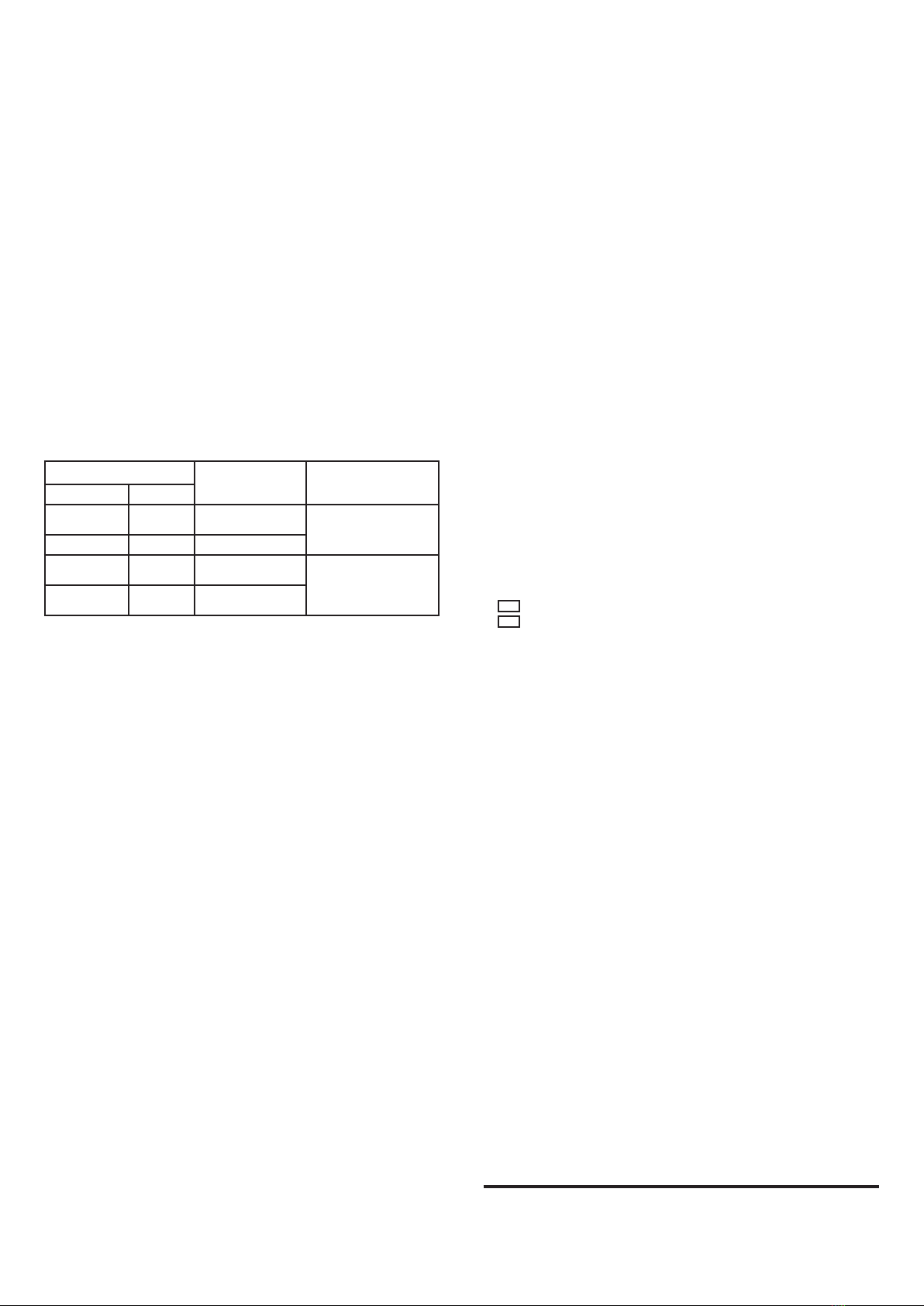
Installation Guide
Figure 1
141
Figure 2
84
63
On the front panel yellow, red and green LED indicators are located.
The LEDs display the BRSS-RK-RTR status (see Table 3). The following
elements are arranged under the BRSS-RK-RTR cover: terminals for
external power supply connection, antennas, ACC (for BRSS-RK-RTR
ver. 1) and microswitch for tamper protection.
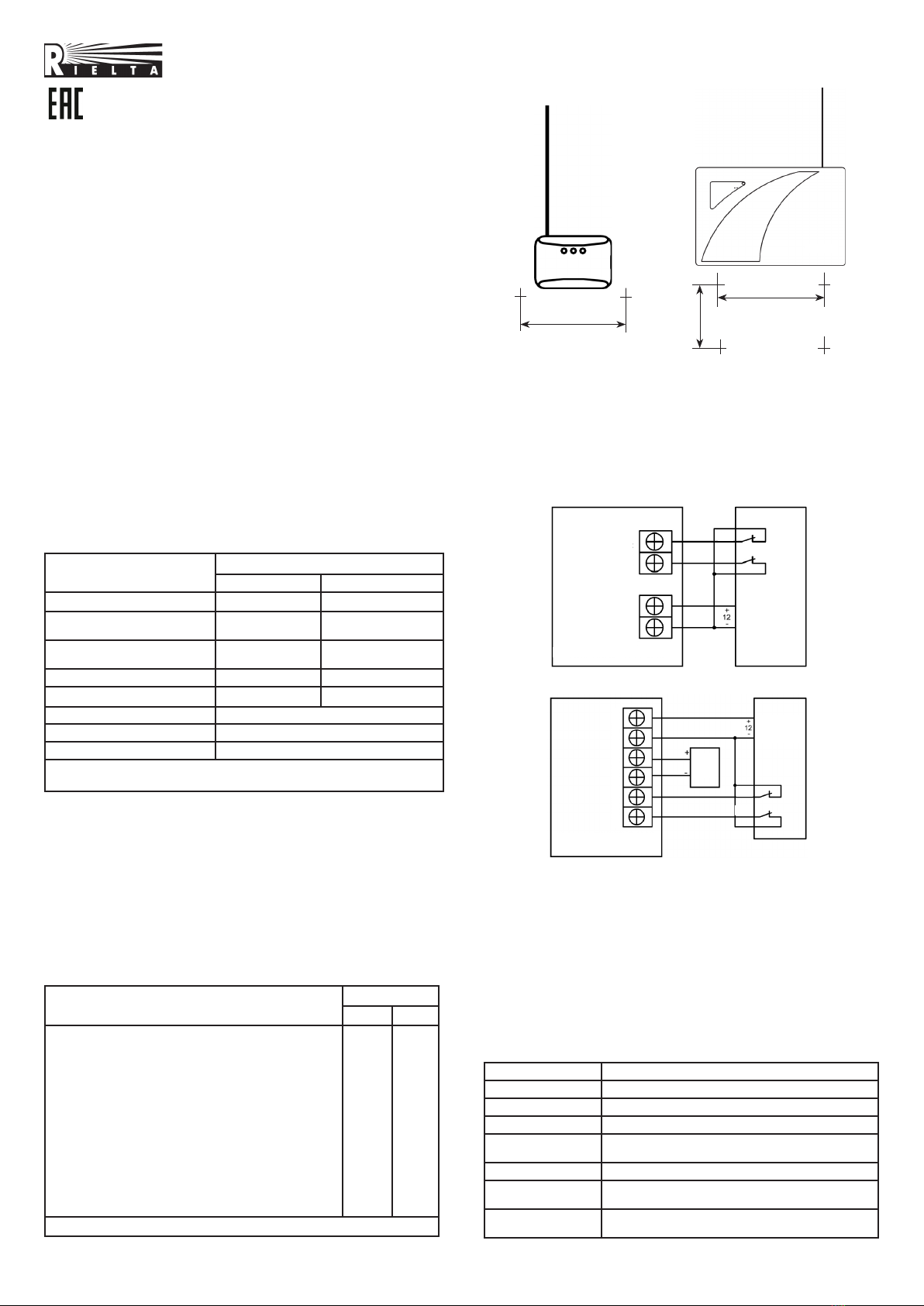
5 BRSS-RK-RTR connection
BRSS-RK-RTR and BRSS-RK-RTR ver. 1 connection is fulfilled in
accordance with connection patterns 3 and 4 correspondingly.
BRSS-RK-RTR ver. 1 provides activation and operation from
preliminary charged ACC during adjustment and setting-up procedures
without connection to external power source. Such operation allows to
choose optimal place of installation ensuring stable radio communication
with Coordinator and TD until wires are installed from the external
power supply to BRSS-RK-RTR ver. 1. To begin ACC operation of
BRSS-RK-RTR ver. 1 it is necessary to press button «Start». Leave
«+CB-»terminals on the PCB disconnected.
6 LED Indication
LED indication modes are listed in Table 3.
Table 3
Operation mode LED Indication
Binding LED indicator intermittent lighting green
Binding is finished LED indicator short-term (2 sec) lighting red
Identification Alternate green and red indicators blinking
Communication
quality appraising See Table 4
Bootloader mode Red LED indicator steadily blinking
ACC discharge Yellow LED indicator steadily blinking
(for BRSS-RK-RTR ver. 1)
External power
supply malfunction
Yellow LED indicator periodical blinking
(for BRSS-RK-RTR ver. 1)
Figure 3
Figure 4
RP
MP
Power
supply
1 Output 2
-12 V+
«Ladoga BRSS-RK-RTR»
Power
supply
ACC
MP
RP
-12 V+ACC1 Input 2
«Ladoga BRSS-RK-RTR»
ver. 1
RIELTA
Ladoga
RK