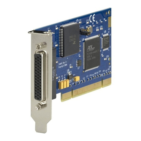
Black Box IC128C-R3 User manual

MARCH 2003
IC128C-R3
PC Plus Adapter
Dual Serial PCI
CUSTOMER SUPPORT INFORMATION
Order toll-free in the U.S. 24 hours, 7 A.M. Monday to midnight Friday: 877-877-BBOX
FREE technical support, 24 hours a day, 7 days a week: Call 724-746-5500 or fax 724-746-0746
Mail order: Black Box Corporation, 1000 Park Drive, Lawrence, PA 15055-1018

1
TRADEMARKS
TRADEMARKS USED IN THIS MANUAL
IBM is a registered trademark of International Business
Machines Corporation.
Windows and Windows NT are either registered
trademarks or trademarks of Microsoft Corporation in
the United States and/or other countries.
Any other trademarks mentioned in this manual are
acknowledged to be the property of the trademark owners.

2
PC PLUS ADAPTER DUAL SERIAL PCI
FEDERAL COMMUNICATIONS COMMISSION
AND
INDUSTRY CANADA
RADIO FREQUENCY INTERFERENCE STATEMENTS
This equipment generates, uses, and can radiate radio frequency energy
and if not installed and used properly, that is, in strict accordance with the
manufacturer’s instructions, may cause interference to radio communication.
It has been tested and found to comply with the limits for a Class A computing
device in accordance with the specifications in Subpart J of Part 15 of FCC rules,
which are designed to provide reasonable protection against such interference
when the equipment is operated in a commercial environment. Operation of
this equipment in a residential area is likely to cause interference, in which case
the user at his own expense will be required to take whatever measures may be
necessary to correct the interference.
Changes or modifications not expressly approved by the party responsible
for compliance could void the user’s authority to operate the equipment.
This digital apparatus does not exceed the Class A limits for radio noise emission from
digital apparatus set out in the Radio Interference Regulation of Industry Canada.
Le présent appareil numérique n’émet pas de bruits radioélectriques dépassant les limites
applicables aux appareils numériques de classe A prescrites dans le Règlement sur le
brouillage radioélectrique publié par Industrie Canada.

3
NOM STATEMENT
NORMAS OFICIALES MEXICANAS (NOM)
ELECTRICAL SAFETY STATEMENT
INSTRUCCIONES DE SEGURIDAD
1. Todas las instrucciones de seguridad y operación deberán ser leídas antes
de que el aparato eléctrico sea operado.
2. Las instrucciones de seguridad y operación deberán ser guardadas para
referencia futura.
3. Todas las advertencias en el aparato eléctrico y en sus instrucciones de
operación deben ser respetadas.
4. Todas las instrucciones de operación y uso deben ser seguidas.
5. El aparato eléctrico no deberá ser usado cerca del agua—por ejemplo,
cerca de la tina de baño, lavabo, sótano mojado o cerca de una alberca,
etc..
6. El aparato eléctrico debe ser usado únicamente con carritos o pedestales
que sean recomendados por el fabricante.
7. El aparato eléctrico debe ser montado a la pared o al techo sólo como sea
recomendado por el fabricante.
8. Servicio—El usuario no debe intentar dar servicio al equipo eléctrico más
allá a lo descrito en las instrucciones de operación. Todo otro servicio
deberá ser referido a personal de servicio calificado.
9. El aparato eléctrico debe ser situado de tal manera que su posición no
interfiera su uso. La colocación del aparato eléctrico sobre una cama,
sofá, alfombra o superficie similar puede bloquea la ventilación, no se
debe colocar en libreros o gabinetes que impidan el flujo de aire por los
orificios de ventilación.

4
PC PLUS ADAPTER DUAL SERIAL PCI
10. El equipo eléctrico deber ser situado fuera del alcance de fuentes de calor
como radiadores, registros de calor, estufas u otros aparatos (incluyendo
amplificadores) que producen calor.
11. El aparato eléctrico deberá ser connectado a una fuente de poder sólo
del tipo descrito en el instructivo de operación, o como se indique en
el aparato.
12. Precaución debe ser tomada de tal manera que la tierra fisica y la
polarización del equipo no sea eliminada.
13. Los cables de la fuente de poder deben ser guiados de tal manera que
no sean pisados ni pellizcados por objetos colocados sobre o contra ellos,
poniendo particular atención a los contactos y receptáculos donde salen
del aparato.
14. El equipo eléctrico debe ser limpiado únicamente de acuerdo
a las recomendaciones del fabricante.
15. En caso de existir, una antena externa deberá ser localizada lejos
de las lineas de energia.
16. El cable de corriente deberá ser desconectado del cuando el equipo
no sea usado por un largo periodo de tiempo.
17. Cuidado debe ser tomado de tal manera que objectos liquidos
no sean derramados sobre la cubierta u orificios de ventilación.
18. Servicio por personal calificado deberá ser provisto cuando:
A: El cable de poder o el contacto ha sido dañado; u
B: Objectos han caído o líquido ha sido derramado dentro
del aparato; o
C: El aparato ha sido expuesto a la lluvia; o
D: El aparato parece no operar normalmente o muestra
un cambio en su desempeño; o
E: El aparato ha sido tirado o su cubierta ha sido dañada.
5
CONTENTS
CONTENTS
1. Specifications..............................................................6
2. Introduction ..............................................................7
2.1 General ................................................................7
2.2 Package Includes..................................................7
3. Quick Install ..............................................................8
4. Hardware Installation................................................9
5. Software Installation ..................................................11
5.1 Windows 95/98/Me/2000/XP Installation ......11
5.1.1 Windows 95/98/Me/2000/XP
Driver Installation ........................................11
5.1.2 Setting Data Rates..........................................14
5.1.3 Setting FIFO Control ....................................17
5.1.4 Flow Control ..................................................20
5.1.5 Redirecting Com Port Names ......................22
5.1.6 Modem Speed Set..........................................24
5.2 Windows NT 4.0 Installation ..............................26
5.2.1 Driver Installation..........................................26
5.2.2 Setting a 230.4 kbps Data Rate ....................28

6
PC PLUS ADAPTER DUAL SERIAL PCI
1. Specifications
System Requirements — IBM®PC or compatible
with Windows®95/98/Me/2000/XP or Windows NT®
Speed — 460.8 kbps
Connectors — (2) DB9
Card Type — PCI
Power — From PC bus
Size — 3⁄4Card

7
CHAPTER 2: Introduction
2. Introduction
2.1 General
The PCI Plus Adapter Dual Serial PCI installs in your
spare PCI port to give you two high-speed serial ports.
It uses PCI shared-interrupt structure, eliminating IRQ
conflicts. It’s 100% compatible with all 56K external
modems and ISDN terminal adapters. Drivers for
Windows 95/98/Me/2000/XP and Windows NT are
included.
2.2 Package Includes
Included in your package, you should have the following
items. If any item is missing or damaged, please contact
your dealer immediately.
• PCI Plus Adapter Dual Serial PCI printed circuit
board
• One software installation diskette
• This user’s manual

8
PC PLUS ADAPTER DUAL SERIAL PCI
3. Quick Install
Windows 95/98/Me/2000/XP
1. Verify the number of Com Ports in your system
(Note that an internal modem uses a Com Port
address).
2. With the power off, place the Adapter into any
free PCI slot.
3. Launch Windows—new hardware will be found.
4. When prompted, insert the Adapter installation
diskette and point Windows to the A drive.
5. After Windows has booted, click the Start button,
then Settings, Control Panel, System, Device
Manager, Ports. The Adapter ports will be listed
as two of your Com Ports. Click “Properties” to
change the default settings as desired.
NOTE
For installation instructions using Windows NT 4.0
see Section 5.2. For Windows 3.1/3.11 installation, refer to
the readme.txt file found in the A:\other directory.

9
CHAPTER 4: Hardware Installation
4. Hardware Installation
1. Before opening the casing of your computer,
make sure that all power is off.
2. Locate an unused PCI slot and insert the Adapter
into it. Make sure that it is well seated.
3. Screw the metal backplane of the Adapter board
to your PC’s casing and replace the machine’s
cover.
4. Connect your modem cable to whichever port on
the Adapter that you would like to use first and
turn the PC on.
NOTE
In standard installations of Windows 2000/XP, the I/O
address cannot be changed to a legacy address.

10
PC PLUS ADAPTER DUAL SERIAL PCI
Figure 4-1. Installing the Adapter.
Screw for attaching card bracket to PC casing
PCI Slot
Port B
Port A

11
CHAPTER 5: Software Installation
5. Software Installation
5.1 Windows 95/98/Me/2000/XP Installation
NOTE
Make sure that you are installing the correct Adapter drivers
for the appropriate operating system. DO NOT install NT
drivers under Windows 95/98/Me/2000/XP.
5.1.1 W
INDOWS
95 D
RIVER
I
NSTALLATION
1. Once the Adapter is installed in your PC, turn
on your computer. Windows will automatically
detect the Adapter as a new PCI Serial Controller
and ask you to insert the Installation diskette.
Insert the diskette as prompted.
2. After the necessary files have been copied,
Windows will complete the full installation of the
Adapter. During this process, a Parent will be
created in Device Manager, and two child ports
will be created in Device Manager/Ports. The
following describes how you may custom configure
these ports for your personal needs.
3. Click on the Start button, then choose Settings,
Control Panel, System, Device Manager. You
should see a window that is similar to the one
shown in Figure 5-1.

12
PC PLUS ADAPTER DUAL SERIAL PCI
Figure 5-1. System Properties window.
4. Click on Ports and select one of the ports listed
under the heading Adapter.
?
System Properties
Properties Refresh Remove Print...
OK Cancel
General Device Manager Hardware Profiles Performance
View devices by type View devices by connection
Secondary IDE controller (single fifo)
Standard Dual PCI IDE Controller
Keyboard
PCI Adapter
PCI Adapter Parent
Modem
Monitor
Mouse
Network Adapters
Ports (COM & LPT)
Communications Port (COM1)
Communications Port (COM2)
PCI Adapter (COM5)
PCI Adapter (COM6)
Printer Port (LPT1)
System Devices

13
CHAPTER 5: Software Installation
5. Click Properties. The screen shown in Figure 5-2
will appear:
Figure 5-2. PCI Properties screen.
The Adapter hardware appears in Device Manager in
two places: under its own tree and as part of the Ports
tree.
?
PCI Adapter (COM5) Properties
OK Cancel
General PCI Settings FIFO Control Flow Control
PCI Adapter (COM5)
Device Usage
Disable in this hardware profile
Exists in all hardware profiles
Device Status
This device is working properly.
Device Type:
Manufacturer:
Hardware Version:
Ports (COM & LPT)
Not Available
Not Available
Driver Resources

14
PC PLUS ADAPTER DUAL SERIAL PCI
NOTE
The Resources (Com Address and IRQ) used by the
individual ports on the Adapter cannot be modified. Interrupt
Resources may be modified in the Parent (see Device
Manager), but not for individual ports because both ports on
the Adapter share one IRQ. Interrupt changes require a
reboot to take effect.
The Com Port designation number of each of the
Adapter’s ports may be changed in software. If you wish
to modify the Com numbering of either port on the
Adapter (for example, Renaming Com 5 to be Com 4),
use the Redirect utility in the Utils subdirectory on your
diskette. See Section 5.1.5.
5.1.2 S
ETTING
D
ATA
R
ATES
You can set the data rate of the Adapter using the Bits
per Second pull-down menu.
NOTE
This menu will also appear when setting the “Port
Properties” in any communications application, and may
have to be set independently of your Control Panel settings.
Control Panel settings may not necessarily be linked to
those of your communications application. For example,
Port speeds in Dial-Up Networking are controlled
independently of speed settings in Device Manager.

15
CHAPTER 5: Software Installation
For optimum performance, always verify that your
Adapter is set to the maximum speed supported by your
modem, and that both speed settings are the same in
every application.
NOTE
The setting of Communications Port Data Rates is often the
most confusing of tasks encountered by modem users. For
this reason, we have included the Modem Speed Set utility
in the Utils subdirectory of your diskette. We strongly
recommend using this utility for all Adapter-to-modem
connection.

16
PC PLUS ADAPTER DUAL SERIAL PCI
Figure 5-3. Com5 Properties screen.
?
PCI Adapter (COM5) Properties
OK Cancel
General PCI Settings FIFO Control Flow Control
To access Help on any function, click the right mouse button
while the mouse pointer is within the appropriate function.
Driver Resources
Restore Defaults
230400
Bits per second:
Data bits:
Parity:
Stop bits:
8
None
1

17
CHAPTER 5: Software Installation
5.1.3 S
ETTING
FIFO C
ONTROL
Each of the Adapter’s two ports incorporates a 32-byte
FIFO (first-in-first-out) buffer.
The FIFO control tabs set the buffer “trigger” levels.
When the buffer is filled to its trigger level with the
selected number of bytes, the CPU will be interrupted
and asked to either reload the buffer (for transmission),
or retrieve data from the buffer (for reception).
Most efficient data transmission occurs when the CPU
is interrupted infrequently. For each interrupt, the CPU
can then service the buffer with larger data blocks:
During transmission, it can place a large burst of data
into the buffer, and during reception it can retrieve a
large block from the buffer and then continue multi-
tasking.
Ideally, therefore, Receive triggers should be set as
high as possible and Transmit triggers as low as possible.
However, if the Transmit trigger levels are set too low,
or Receive triggers too high, and the CPU is busy when
an interrupt is called by the Adapter, a short period of
inactivity may occur between the port and the modem.
This will reduce effective transmission/reception speeds.

18
PC PLUS ADAPTER DUAL SERIAL PCI
Optimum buffer settings depend on your modem
speed, your CPU speed, and the amount of multi-tasking
that occurs while online. For a fast modem and fast CPU
performing few multi-tasking functions, set transmit
triggers low and receive triggers high. If multi-tasking
while online, set transmit triggers higher and receive
triggers lower.

19
CHAPTER 5: Software Installation
Figure 5-4. FIFO Control screen.
?
PCI Adapter (COM5) Properties
OK Cancel
General PCI Settings FIFO Control Flow Control
To access Help on any function, click the right mouse button
while the mouse pointer is within the appropriate function.
Driver Resources
Receive Buffer:
24
Defaults
Transmit Block Actual Value:
302481
3024168
Transmit Buffer:
+20-2-5
Transmit Block:
+1-4 -1-3
Table of contents
Other Black Box PCI Card manuals

Black Box
Black Box IC142C User manual

Black Box
Black Box IC142C User manual

Black Box
Black Box IC136C User manual

Black Box
Black Box USB Director RS-232 User manual

Black Box
Black Box LH1390C-SC-R2 User manual

Black Box
Black Box IC970C User manual

Black Box
Black Box IC126C User manual

Black Box
Black Box USB Director RS-232 User manual

Black Box
Black Box RS-422 User manual

Black Box
Black Box IC142C User manual