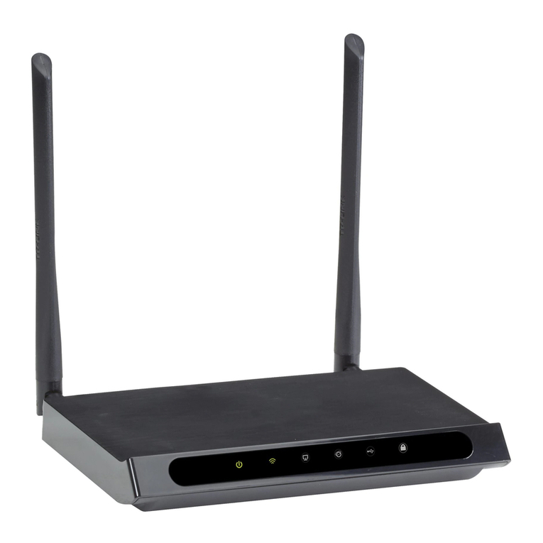
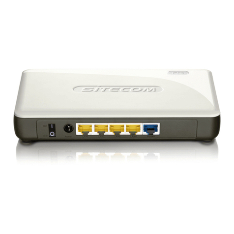
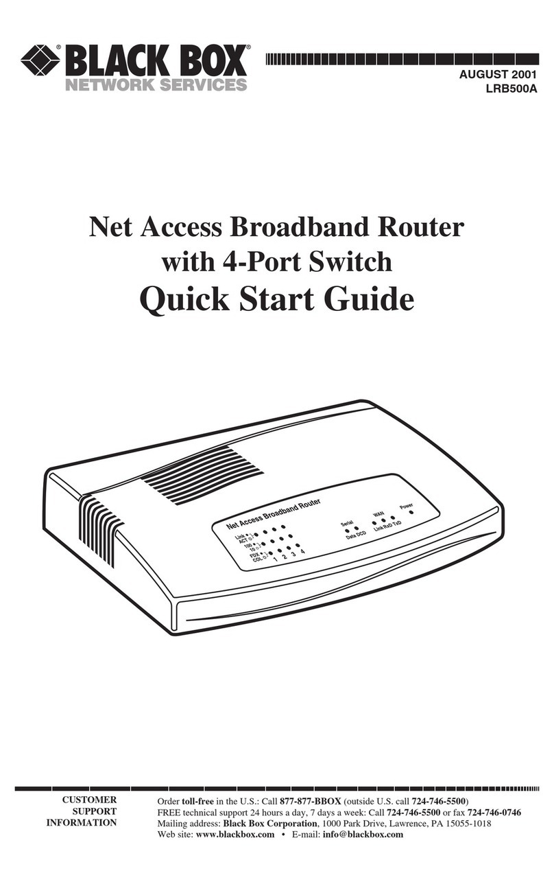
Black Box WRT4001A User manual

Single box solution for Internet/WAN access, VPN,
firewall, Ethernet switching, and legacy protocol
to IP internetworking.
Approved for user with Verizon®, AT&T®, Sprint®, and international carriers.
Commerical and industrial packages available.
WRT4000 Series Cellular Wireless Routers User Manual
WRT4001A WRT4011A WRT4001A-DC WRT4000-DIN
WRT4002A WRT4012A WRT4002A-DC WRT4000-PM
WRT4003A WRT4013A WRT4003A-DC WRT4000-ANT
WRT4004A WRT4014A WRT4004A-DC WRT4000-ANT-KIT
Order toll-free in the U.S.: Call 877-877-BBOX (outside U.S. call 724-746-5500)
FREE technical support 24 hours a day, 7 days a week: Call 724-746-5500 or fax 724-746-0746
Mailing address: Black Box Corporation, 1000 Park Drive, Lawrence, PA 15055-1018
Web site: www.blackbox.com • E-mail: info@blackbox.com
Customer
Support
Information

724-746-5500 | blackbox.com
Page 2
Trademarks Used in this Manual
We‘re here to help! If you have any questions about your application
or our products, contact Black Box Tech Support at 724-746-5500
or go to blackbox.com and click on “Talk to Black Box.”
You’ll be live with one of our technical experts in less than 60 seconds.
Trademarks Used in this Manual
Black Box and the Double Diamond logo are registered trademarks of BB Technologies, Inc.
AT&T is a registered trademark of AT&T Inc.
Sprint is a registered trademark of Sprint.
Verizon is a registered trademark of Verizon Wireless, Inc.
Any other trademarks mentioned in this manual are acknowledged to be the property of the trademark owners.

724-746-5500 | blackbox.com Page 3
FCC and IC RFI Statements
Federal Communications Commission and Industry Canada Radio Frequency Interference
Statements
This equipment generates, uses, and can radiate radio-frequency energy, and if not installed and used properly, that is, in strict
accordance with the manufacturer’s instructions, may cause interference to radio communication. It has been tested and found to
comply with the limits for a Class A computing device in accordance with the specifications in Subpart B of Part 15 of FCC rules,
which are designed to provide reasonable protection against such interference when the equipment is operated in a commercial
environment. Operation of this equipment in a residential area is likely to cause interference, in which case the user at his own
expense will be required to take whatever measures may be necessary to correct the interference.
Changes or modifications not expressly approved by the party responsible for compliance could void the user’s authority to
operate the equipment.
This digital apparatus does not exceed the Class A limits for radio noise emission from digital apparatus set out in the Radio
Interference Regulation of Industry Canada.
Le présent appareil numérique n’émet pas de bruits radioélectriques dépassant les limites applicables aux appareils numériques
de la classe A prescrites dans le Règlement sur le brouillage radioélectrique publié par Industrie Canada.
Disclaimer:
Black Box Network Services shall not be liable for damages of any kind, including, but not limited to, punitive, consequential or cost of cover damages, resulting
from any errors in the product information or specifications set forth in this document and Black Box Network Services may revise this document at any time
without notice.

724-746-5500 | blackbox.com
Page 4
NOM Statement
Instrucciones de Seguridad
(Normas Oficiales Mexicanas Electrical Safety Statement)
1. Todas las instrucciones de seguridad y operación deberán ser leídas antes de que el aparato eléctrico sea operado.
2. Las instrucciones de seguridad y operación deberán ser guardadas para referencia futura.
3. Todas las advertencias en el aparato eléctrico y en sus instrucciones de operación deben ser respetadas.
4. Todas las instrucciones de operación y uso deben ser seguidas.
5. El aparato eléctrico no deberá ser usado cerca del agua—por ejemplo, cerca de la tina de baño, lavabo, sótano mojado o cerca
de una alberca, etc.
6. El aparato eléctrico debe ser usado únicamente con carritos o pedestales que sean recomendados por el fabricante.
7. El aparato eléctrico debe ser montado a la pared o al techo sólo como sea recomendado por el fabricante.
8. Servicio—El usuario no debe intentar dar servicio al equipo eléctrico más allá a lo descrito en las instrucciones de operación.
Todo otro servicio deberá ser referido a personal de servicio calificado.
9. El aparato eléctrico debe ser situado de tal manera que su posición no interfiera su uso. La colocación del aparato eléctrico
sobre una cama, sofá, alfombra o superficie similar puede bloquea la ventilación, no se debe colocar en libreros o gabinetes
que impidan el flujo de aire por los orificios de ventilación.
10. El equipo eléctrico deber ser situado fuera del alcance de fuentes de calor como radiadores, registros de calor, estufas u otros
aparatos (incluyendo amplificadores) que producen calor.
11. El aparato eléctrico deberá ser connectado a una fuente de poder sólo del tipo descrito en el instructivo de operación, o como
se indique en el aparato.
12. Precaución debe ser tomada de tal manera que la tierra fisica y la polarización del equipo no sea eliminada.
13. Los cables de la fuente de poder deben ser guiados de tal manera que no sean pisados ni pellizcados por objetos colocados
sobre o contra ellos, poniendo particular atención a los contactos y receptáculos donde salen del aparato.
14. El equipo eléctrico debe ser limpiado únicamente de acuerdo a las recomendaciones del fabricante.
15. En caso de existir, una antena externa deberá ser localizada lejos de las lineas de energia.
16. El cable de corriente deberá ser desconectado del cuando el equipo no sea usado por un largo periodo de tiempo.
17. Cuidado debe ser tomado de tal manera que objectos liquidos no sean derramados sobre la cubierta u orificios de ventilación.
18. Servicio por personal calificado deberá ser provisto cuando:
A: El cable de poder o el contacto ha sido dañado; u
B: Objectos han caído o líquido ha sido derramado dentro del aparato; o
C: El aparato ha sido expuesto a la lluvia; o
D: El aparato parece no operar normalmente o muestra un cambio en su desempeño; o
E: El aparato ha sido tirado o su cubierta ha sido dañada.

724-746-5500 | blackbox.com Page 5
Table of Contents
Table of Contents
1. Specifications.........................................................................................................................................................................8
2. Overview ...............................................................................................................................................................................9
2.1 Description ....................................................................................................................................................................9
2.2 Features....................................................................................................................................................................... 10
2.3 What’s Included .......................................................................................................................................................... 11
2.4 Hardware Description.................................................................................................................................................. 12
2.4.1 Front Panel ........................................................................................................................................................ 12
2.4.2 Back Panel......................................................................................................................................................... 13
2.4.3 LED Indicators on the Router............................................................................................................................. 14
2.4.4 Dual Serial Port Module .................................................................................................................................... 15
2.4.5 10BASE-T/100BASE-T Ethernet Port .................................................................................................................. 16
3. Installation ........................................................................................................................................................................... 17
3.1 Collecting the Items Needed for Installation................................................................................................................ 17
3.2 Viewing the Ports on the WRT4000 Series Chassis ..................................................................................................... 17
3.3 Replacing the Subscriber Identity Module ................................................................................................................... 18
3.4 How to Install or Replace a SIM for a GSM or LTE Module in a WRT4000 Series Router............................................ 18
3.5 Connecting and Starting the WRT4000 Series Router Chassis ....................................................................................25
3.6 Connecting the WRT4000 Series Router to DC Power................................................................................................ 27
3.7 The Next Step..............................................................................................................................................................32
4. Configuration—General Settings ........................................................................................................................................33
4.1 Using the WRT4000 Router‘s Management System....................................................................................................33
4.1.1 Connecting to the WRT4000 Series Cellular Wireless Router.............................................................................33
4.1.2 Logging In .........................................................................................................................................................33
4.1.3 Managing the Browser Display ..........................................................................................................................36
4.2 Navigating the WRT4000 Series Cellular Wireless Router’s Management System .......................................................37
4.2.1 Saving or Discarding Changes ...........................................................................................................................37
4.2.2 Restarting (Rebooting) the WRT4000 Series Cellular Wireless Router...............................................................38
4.2.3 Ending the Session............................................................................................................................................39
4.3 Basic Configuration .....................................................................................................................................................39
4.3.1 Revising Lists in the WRT4000 Series Cellular Wireless Router’s Management System......................................39
4.3.2 Configuring the Management System Language..............................................................................................39
4.3.3 Configuring the Device Name and Time of Day................................................................................................40
4.3.4 Configuring System Logging .............................................................................................................................42
4.3.5 Synchronizing the WRT4000 Series Cellular Wireless Router’s Time of Day ......................................................43
4.3.5.1 Configuring Time-of-Day Synchronization...............................................................................................43
4.3.5.2 Selecting Time-of-Day Synchronization...................................................................................................45
4.3.6 Overriding the MAC Information ......................................................................................................................46
4.4 Configuration for the Network....................................................................................................................................47
4.4.1 DHCP and DNS..................................................................................................................................................47
4.4.2 Network Hosts..................................................................................................................................................49
4.4.3 Routing .............................................................................................................................................................50
4.4.4 Firewall Configuration ....................................................................................................................................... 51
4.4.5 Configuring Traffic Priority ................................................................................................................................54
5. Configuring the Serial Ports.................................................................................................................................................55
5.1 Connecting to the WRT4000 Series Cellular Wireless Router ......................................................................................55
5.2 Configuring a Serial Port .............................................................................................................................................55

724-746-5500 | blackbox.com
Page 6
Table of Contents
6. Configuring Chassis Ports....................................................................................................................................................63
6.1 Port Interfaces .............................................................................................................................................................63
6.1.1 Configuring a LAN Port .....................................................................................................................................64
6.1.2 Configuring the WAN Port ................................................................................................................................67
7. Configuring a MultiWAN for the WRT4000 Series Cellular Wireless Router........................................................................ 70
7.1 Use of a MultiWAN .....................................................................................................................................................70
7.2 Configuring a MultiWAN............................................................................................................................................. 71
8. Virtual Private Networks......................................................................................................................................................80
8.1 VPN Configuration in the WRT4000 Series Cellular Wireless Router ...........................................................................80
8.1.1 Configuring VPNs in the WRT4000 Series Cellular Wireless Router ...................................................................80
8.1.2 Starting the Tunnel ............................................................................................................................................85
8.2 Testing and Tracking VPN Connections .......................................................................................................................85
8.2.1 Testing VPN Connections ..................................................................................................................................85
8.2.2 Tracking VPN Connections ................................................................................................................................87
8.2.2.1 Tracking Specific Information ..................................................................................................................87
8.2.2.2 Tracking General VPN Activity ................................................................................................................90
8.3 VPN Basics...................................................................................................................................................................92
8.3.1 A Simple Virtual Private Network ......................................................................................................................93
8.3.2 Tunnel Modes ...................................................................................................................................................94
8.3.2.1 Tunnel Initiation ...................................................................................................................................94
8.3.2.2 Tunnel Termination..............................................................................................................................94
8.3.2.3 Tunnel Passthrough .............................................................................................................................95
8.3.3 Tunnel Support .................................................................................................................................................96
8.3.3.1 Tunnel Sharing .....................................................................................................................................96
8.3.3.2 Tunnel Switching .................................................................................................................................96
8.3.3.3 Split Tunneling .....................................................................................................................................97
8.3.4 Internet Key Exchange.......................................................................................................................................97
8.3.4.1 Perfect Forward Secrecy ......................................................................................................................97
8.3.4.2 IKE Version 1 .......................................................................................................................................97
8.3.4.3 IKE Version 2 .......................................................................................................................................98
8.4 Developing a Virtual Private Network........................................................................................................................ 102
8.4.1 VPN Configuration Plan................................................................................................................................... 102
8.4.2 Automatic Keying ...........................................................................................................................................104
8.4.3 Sample Configuration for a Remote User........................................................................................................105
9. Monitoring the WRT4000 Router...................................................................................................................................... 107
9.1 Monitoring ................................................................................................................................................................ 107
9.1.1 Collection of Statistics......................................................................................................................................108
9.1.2 Graphs..............................................................................................................................................................111
9.1.2.1 Displaying Graphs Ending at the Current Time .....................................................................................111
9.1.2.2 Displaying Graphs Beginning at the Current Time............................................................................... 112
9.1.3 Routing Information ....................................................................................................................................... 116
9.1.4 Pings and Other Network Diagnostics............................................................................................................ 116
9.1.5 Firewall Statistics............................................................................................................................................. 118
9.1.6 System Processes ............................................................................................................................................ 119
9.1.7 Logs ................................................................................................................................................................ 120
Appendix A. Setting the WRT4000 Series Cellular Wireless Router’s APN .............................................................................. 124
Appendix B. Glossary.............................................................................................................................................................. 126
Appendix C. Basic Safety Guidelines ......................................................................................................................................140

724-746-5500 | blackbox.com Page 7
Chapter 1: Specifications
1. Specifications
Management SNMP v3,
GUI Web management,
Telnet,
SSH (secure shell),
Syslog
Security Stateful inspection firewall,
IEEE 801.22i (WPA2, RSN),
DMZ LAN port,
NAT (Network Address Translation),
SSL / TLS1,
SSH (Secure Shell),
IP Sec (RFC 2401) with AES 256 and 3DES,
Generic Router Encapsulation GRE (RFC 1701),
Internet Key Exchange (IKE) RFC-2409
Serial Data Support Industrial models (WRT4001A–WRT4004A, WRT4001A-DC–WRT4004A-DC): Up to (2)
serial ports supporting TIA RS-485, RS-232
NOTE: Contact Black Box Technical Support at 724-746-5500 or info@blackbox.com for
additional protocols.
Transport Protocols WAN:
IP over Ethernet (compatible with MPLS services),
Asynchronous PPP,
Synchronous PPP,
MLPPP,
PPPoE,
Selective Layer Encryption (SLE) for VPN optimization (patented);
IP:
IP versions 4 and 6,
IP routiing (RIP v1/v2), OSPF, BGP, or static routing,
DHCP client/server/BootP/Relay,
IP QoS and traffic prioritization,
IP fragmentation/assembly,
IP routing over VPN; TCP ad UDP,
802.1q VLAN tagging,
Virtual Redundant Routing Protocol (VRRP) between two routers,
Dead Peer Detection
User Controls Front panel: Reset switch
Connectors All models (includes industrial and commericial models):
Front panel:
(1) USB host port,
(1) main antenna connector for internal wireless module;
Back panel:
(1) auxiliary antenna connector for internal wireless module,
(1) 10/100 Mbps Ethernet RJ-45 (WAN),
(4) RJ-45 10/100 Mbps switched Ethernet LAN ports,
(1) 5-VDC input (from AC line-power adapter),
WRT4001A-DC–WRT4004A-DC: (1) connector for 24-VDC input;
WRT4001A–WRT4004A, WRT4001A-DC–WRT4004A-DC industrial units only include:
(2) RJ-45 (RS-232/RS-485)

724-746-5500 | blackbox.com
Page 8
Chapter 1: Specifications
1. Specifications (continued)
Indicators Front panel:
(4) LEDs for module, system status, and power;
(4) LEDs for wireless signal strength indication for one cellular module,
(4) LEDs not used at this time;
Back panel:
(4) TX, (4) LNK/RX LEDs for RJ-45 LAN ports,
(1) TX, (1) LNK/RX LEDs for WAN port
Environmental Temperature Tolerance:
Operating:
Industrial Hardened: -40 to +185° F (-40 to +85 C),
Extended Temperature Commercial: -4 to 149 F (-20 to +65 C);
Humidity: 5 to 95%, noncondensing
Power DC models: 24 VDC, 13 watts maximum,
AC models: 100–240 VAC, autoranging adapter, 50–60 Hz, 5 VDC, 3 A output,
15 W max.
Dimensions 1.6"H x 5.7"W x 4"D (4 x 14.5 x 10 cm)
Weight Metal case (WRT4001A–WRT4004A, WRT4001A-DC–WRT4004A-DC:
0.85 lb. (0.39 kg);
Plastic case (WRT4011A–WRT4014A):
0.75 lb. (0.34 kg)
Approvals FCC Part 15,
EN55011/CISPR II,
IEC 61850-3,
IEEE 1613;
UL®/CSA 60950-1,
CAN/CSA-C22.2 No. 60950-1-03,
EN 60950-1

724-746-5500 | blackbox.com Page 9
Chapter 2: Overview
2. Overview
2.1 Description
The WRT4000 Series Router provides speed, capacity, and flexibility for wired, optical fiber, and cellular uplinks; complete remote
management; and support for current and legacy data protocols.
The WRT4000 Series Router chassis is designed to operate in industrial or commercial environments with a wide range of
ambient temperatures. The industrial versions have a tight all-metal enclosure that resists dust, moisture, and electromagnetic
interference (EMI). The commercial versions have a plastic enclosure that resists dust, moisture, and EMI.
The WRT4000 Series Router has expanded memory and a high-speed processor that allow it to handle multiple ports and high-
speed network connections while converting protocols, routing packets, and applying firewall rules and other security measures.
With an optional encryption-chip module, a single WRT4000 Series Router can terminate more than 1,000 virtual private
network (VPN) tunnels without affecting other features. One internal cellular wireless module is standard on the industrial and
commercial routers (all part numbers). The industrial routers (part numbers WRT4001A–WRT4004A and WRT4001A-DC–
WRT4004A-DC) also have a dual-port serial expansion module installed in one of the expansion slots.
Up to two antennas handle 3G/4G/LTE cellular and advanced Wi-Fi.
There is no cooling fan or other moving parts. All models are built on the same hardware platform.
The WRT4000 Series Router requires minimal power. Typical configurations draw less than 13 W. The power source options are:
• an AC power supply unit (PSU)
• a DC input line, at several voltages
The power input sources provide 5 VDC to the chassis.
NOTE: A DC power input can form a redundant pair with an AC power input: One is the chassis’s primary input power source,
and the other source provides power if the primary source is down.
Table 2-1. Available models, internal modules installed.
Part Number Product Name/Description
WRT4001A VZ 4G/LTE Industrial Router, Metal Case, AC Power
WRT4002A VZ 3G Industrial Router, Metal Case, AC Power
WRT4003A ATT 4G LTE/HSPA+ Industrial Router, Metal Case, AC Power
WRT4004A Sprint 3G Industrial Router, Metal Case, AC Power
WRT4001A-DC VZ 4G/LTE Industrial Router, Metal Case, 24 VDC Power
WRT4002A-DC VZ 3G Industrial Router, Metal Case, 24 VDC Power
WRT4003A-DC ATT 4G LTE/HSPA+ Industrial Router, Metal Case, 24 VDC Power
WRT4004A-DC Sprint 3G Industrial Router, Metal Case, 24 VDC Power
WRT4 011A VZ 4G/LTE Commercial Router, Plastic Case, AC Power
WRT4012A VZ 3G Commercial Router, Plastic Case, AC Power
WRT4013A ATT 4G LTE/HSPA+ Commercial Router, Plastic Case, AC Power
WRT4014A Sprint 3G Commercial Router, Plastic Case, AC Power

724-746-5500 | blackbox.com
Page 10
Chapter 2: Overview
Table 2-2. Optional accessories.
Part Number Product Name/Description
WRT4000-DIN Optional DIN Rail Mounting Kit Available for Metal Case Packages
WRT4000-PM Optional Panel Mount Kit Available for Metal Case Packages
WRT4000-RM Optional Right-Angle Bracket Mounting Kit Available for Metal Case Packages
WRT4000-ANT Optional Indoor 3G/4G Antenna
WRT4000-ANT-KIT Optional Indoor Magnetic Pedestal, 8-Foot Cable Antenna
2.2 Features
• Commercial or industrial versions with redundant power sources include: 120-VAC or 24-VDC.
• Provides service over any port, any network, at any time, including cellular 3G, 4G, LTE, and Ethernet.
• Automatic failover with traffic load sharing between wireline and wireless links.
• VPN IP Security (IPSec), AES 256 and 3DES, SSL/TLS and SSH.
• Operation, administration, and management (OA&M) with Web-based GUI management.
Industrial Routers
• Metal case resists dust, moisture, and EMI.
• Temperature Tolerance:
Operating:
Industrial Hardened: -40 to +185° F (-40 to +85° C);
Humidity: 5 to 95%, noncondensing
Commercial Routers
• Plastic case
• Temperature Tolerance:
Operating: Extended Temperature Commercial: -4 to +149° F
(-20 to +65° C);
Humidity: 5 to 95%, noncondensing

724-746-5500 | blackbox.com Page 11
Chapter 2: Overview
2.3 What’s Included
• WRT4000 Series Cellular Wireless Router
• AC or DC power supply
• (1) to (2) antennas
• Quick Start Guide
The full user manual/installation guide can be downloaded from the Black Box Web site.
To download from the Web site:
1. Go to www.blackbox.com
2. Enter the part number (for example, WRT4001A) in the search box:
3. Click on the “Resources” tab on the product page, and select the document you wish to download.

724-746-5500 | blackbox.com
Page 12
Chapter 2: Overview
2.4 Hardware Description
2.4.1 Front Panel
USB
Port
*Industrial model: left slot: installed
card with (2) serial ports
LEDs for
Power and
Status
LEDs (not
used)
LEDs for signal
strength for
internal wireless
module
Main antenna port for
internal wireless module
Figure 2-1. WRT4001A–WRT4004A, WRT4001A-DC–WRT4004A-DC Series Router front panel.
*NOTE: The industrial routers (part numbers WRT4001A–WRT4004A and WRT4001A-DC–WRT4004A-DC) have one dual-port
serial module pre-installed in one of the empty expansion slots. The commerical models (WRT4011A–WRT4014A) do not
have any expansion modules installed. Additional expansion modules for the routers are not available at this time, but
may be included in a future product release.
USB
Port *Commercial model: empty slots
LEDs for
Power and
Status
LEDs (not
used)
LEDs for signal
strength for
internal wireless
module
Main antenna port for
internal wireless module
Figure 2-2. WRT4011A–WRT4014A Series Router front panel.

724-746-5500 | blackbox.com Page 13
Chapter 2: Overview
2.4.2 Back Panel
Auxiliary antenna port
for internal wireless module
Port for AC power
adapter input
Ethernet WAN port (eth 0)
Ethernet LAN ports (eth 1)
Figure 2-3. WRT4000 Series Router back panel, AC power versions (WRT4001A–WRT4004A, WRT4011A–WRT4014A).
Auxiliary antenna port
for internal
wireless module DC power connector
Ethernet WAN port (eth 0)
Ethernet LAN ports (eth 1) Port for AC power
adapter input
Figure 2-4. WRT4000 Series Router back panel, DC power versions (WRT4001A-DC–WRT4004A-DC).

724-746-5500 | blackbox.com
Page 14
Chapter 2: Overview
Table 2-3. Components on the WRT4000 Series Cellular Wireless Router.
Number in Fig. 2-1–2-4 Component Description
1(1) Power LED Lights when power to the unit is on
2(3) LEDs For module and system status
3(1) USB port
4(2) external antenna connectors For internal wireless ports
5(2) groups of (4) LEDs For cellular wireless signal strength
6(1) Reset switch For default software/configuration load
7(2) empty slots Currently not used
8(2) external auxiliary antenna
connectors
For factory-installed internal wireless modules
(cellular 3G, EVDO, or 4G; Wi-Fi; or Bluetooth)
9(1) RJ-45 port 10/100 Ethernet (WAN) port
10 (4) RJ-45 ports 10/100 switched Ethernet (LAN)
11 (1) 5-VDC input port From AC power adapter
NOTE: The WRT4000 Series Router chassis that uses DC power also has a 24-VDC port.
2.4.3 LED Indicators on the Router
Each group of 4 LEDs indicates the status of a connection to a cellular wireless network and the strength of signals from that
network:
• The number of LEDs that light up (1 to 4 lights) indicates the signal strength.
• 1 to 4 steady (unblinking) LEDs indicate that the port is connected to a cellular wireless network.
• 1 to 4 blinking LEDs indicate that a network is available but that the port does not have an IP address. (In this case, configure an
IP address for the port, so that the port can connect to the network. See Chapter 4, Configuration.
The following general rules apply to the WRT4000 Series Router’s LEDs:
• A lit green Power LED indicates that the unit is being supplied with power.
• A lit green Link LED indicates that there is a connection to another device, including an Ethernet hub or switch.
• A flashing Alarm LED indicates that the WRT4000 Series Router has detected an alarm, or that the system needs attention, or
that power to the system has failed.
Table 2-4 describes the LEDs on the WRT4000 Series Router chassis.

724-746-5500 | blackbox.com Page 15
Chapter 2: Overview
Table 2-4. General Status LEDs definitions.
LED Color Description
Power Green Unit is receiving power.
Green (flashing) A port has an alarm or the system needs attention.
Off Unit is not receiving power.
Status Green Connected to management terminal (or to carrier, if the port is used for
data).
Off Not connected.
WAN port (Ethernet port) Green Connected to WAN gateway (Ethernet hub or switch).
Off Connection to WAN gateway has failed.
LAN port (Ethernet port) Green Connected to a supported Ethernet device or connected to the LAN
(connected to an Ethernet hub or switch).
Off Not connected to the LAN.
Cellular Green (not flashing) Connected to a cellular wireless carrier.
Green (Flashing) A cellular wireless network is sending a signal, but the wireless port has
not been configured.
Off Not activated. The device has not been authenticated for a wireless
carrier and is not receiving a signal.
2.4.4 Dual-Serial Port Module
The industrial routers (part numbers WRT4001A–WRT4004A and WRT4001A-DC–WRT4004A-DC) have one dual-port serial
module pre-installed in one of the empty expansion slots. No additional expansion modules are available at this time.
Figure 2-5 shows the dual serial-port module for the industrial routers (WRT4001A–WRT4004A and WRT4001A-DC–WRT4004A-
DC).
NOTE: Commercial WRT4000 Series Routers (WRT4011A–WRT4014A) do not have the serial module.
As the name indicates, this module provides two serial ports. The serial ports use RJ-45 connections.
Figure 2-5. Dual serial port module (present in industrial models).
Figure 2-6 shows the pin locations on an RJ-45 Ethernet port. Table 2-5 lists the pin configuration for the WRT4000 Series
Router’s RJ-45 serial ports.
Figure 2-6. Pin locations for female RJ-45 serial connector.

724-746-5500 | blackbox.com
Page 16
Chapter 2: Overview
Table 2-5. RJ-45 serial port pin configuration.
RJ-45 Pin Number in Fig. 2-6 RS-232 RS485HD RS485FD
1DSR/RI (O) TX/RX+ (BI) RXD+ (O)
2DCD (O) TX/RX- (BI) RXD- (O)
3DTR (I) N/A TXD- (I)
4SGND SGND SGND
5RD (O) DSR (O) DSR (O)
6TD (I) N/A TXD+ (I)
7CTS (O) CTS (O) CTS (O)
8RTS (I) RTS (I) RTS (I)
The serial port options are RS-232 DCE, RS-485 half-duplex, and RS-485 full-duplex. The supported protocols (selectable in soft-
ware) are asynchronous encapsulation and telnet terminal.
2.4.5 RJ-45 10BASE-T/100BASE-T Ethernet Port
Figure 2-7 shows the pin locations on an RJ-45 Ethernet port. Table 2-6 lists the pin configuration for the WRT4000 Series
Router’s 10/100BASE-T Ethernet ports.
NOTE: These ports are present on both industrial and commercial routers.
Figure 2-7. Pin locations for female RJ-45 Ethernet connector.
NOTE: The WRT4000 Series Router senses the pin configuration at the remote end of the connection and sets its own pin
configuration accordingly.
Table 2-6. 10BASE-T/100BASE-T Ethernet port pin configuration.
Pin Set Description
1 and 2 Tx or Rx
3 and 6 Rx or Tx
NOTES:
1. Unused pins are not listed.
2. The WRT4000 Series Router Ethernet connectors are autosensing and will adjust to the signals from the device at the remote
end of the connection.

724-746-5500 | blackbox.com Page 17
Chapter 3: Installation
3. Installation
3.1 Collect the Items Needed for Installation
1. Get everything out of the shipping box. It should contain:
• A Quick Installlation Guide
• WRT4000 Series Cellular Wireless Router1
• DC connector set or AC power adapter
• Antennas (ordered separately)
2. Get additional items required to install the WRT4000 Series Cellular Wireless Router. You will need:
• Computer with Web-browsing software2
• Ethernet cable
• Subscriber Identity Module (SIM)3
• Cellular wireless network account3
NOTES:
1
This quick discussion assumes that there will be one embedded cellular module and the miniPCIe slot will not be in use.
2JavaScript must be enabled in the Web browser.
3
The embedded cellular module must have a cellular wireless network account and a Subscriber Identity Module (SIM) for that
account. Order each SIM from a cellular wireless network provider. SIMs are not shipped with the Router.
3.2 Viewing the Ports on the WRT4000 Series Router Chassis
WRT4001A–WRT4004A, WRT4001A-DC–WRT4004A-DC Series
USB
Port
Industrial model: left slot: installed card
(not shown) with (2) serial ports
LEDs for
Power and
Status
LEDs (not
used)
LEDs for signal
strength for
internal wireless
module
Main antenna port for
internal wireless module
WRT4011A–WRT4014A Series
USB
Port Commercial model: empty slots
LEDs for
Power and
Status
LEDs (not
used)
LEDs for signal
strength for
internal wireless
module
Main antenna port for
internal wireless module
Figure 3-1. WRT4000 Series Router front panel.

724-746-5500 | blackbox.com
Page 18
Chapter 3: Installation
Auxiliary antenna port
for internal
wireless module
Port for AC power
adapter input
Antenna port
(not used)
Ethernet WAN port (eth 0)
Ethernet LAN ports (eth 1)
Figure 3-2. WRT4000 Series Router back panel, AC power (WRT4001A–WRT4004A, WRT4011A–WRT4014A).
Auxiliary antenna port
for internal
wireless module DC power connector
Antenna port
(not used)
Ethernet WAN port (eth 0)
Ethernet LAN ports (eth 1) Port for AC power
adapter input
Figure 3-3. WRT4000 Series Router back panel, DC power and AC power (WRT4001A-DC–WRT4004A-DC).
3.3 Replacing the Subscriber Identity Module
The WRT4000 Series Router holds one wireless card. You will need to put a Subscriber Identity Module (SIM) into place for GSM
cards and LTE cards. (A SIM is sometimes called a GSM or LTE smartcard.)
A GSM cellular wireless module or an LTE cellular wireless module supports a removable SIM to identify the user to the GSM or
LTE network. When you order your WRT4000 Series Router’s wireless card, you specify which carrier and network the card will
use. If you specify a GSM or LTE module, you must order a SIM from the selected GSM or LTE carrier. The carrier provides a SIM
with the carrier’s chip.
NOTE: The WRT4000 Series Router is not a traveling device, so you will not need SIMs for different countries. However, if you
change wireless providers, the WRT4000 Series Router’s GSM or LTE card will need a SIM from the new provider. To install
a new SIM, use the following procedure.
3.4 How to Install or Replace a SIM for a GSM or LTE Module in the WRT4000 Series Router
WARNING: Follow proper procedures and observe all precautions to guard against electrical shock and to protect the device
against electrostatic discharge (ESD) when removing or installing modules in an WRT4000 Series Router device. (For
example, keep the device grounded, wear an ESD wrist-strap, and so forth.) For more information, see the Basic
Safety Guidelines.
Allow only qualified service personnel to install and maintain this equipment.
NOTE: After you replace the SIM, you must activate the SIM’s GSM or LTE card in the carrier network. The former activation of
the card (with its former SIM) is no longer valid.
1. Unplug the WRT4000 Series Router device’s power supply from the power source.
CAUTION: To prevent electrical shock, turn off power to the equipment before disconnecting cables.
2. Disconnect all network connections.
3. Place the chassis on a flat, stable surface.

724-746-5500 | blackbox.com Page 19
Chapter 3: Installation
4. Do the following:
a. Turn the chassis over so that it is resting on its top.
b. Remove the screws from the sides of the chassis, and lift the chassis shell off the bottom of the chassis.
5. Locate the SIM sockets on the bottom of the WRT4000 Series Router motherboard (Figure 3-4).
NOTE: The SIM sockets shown in this document are generic representations. The SIM sockets on your WRT4000 Series Router
may look different.
Edge of board against front of chassis
SIM socket for
embedded GSM
or LTE module
SIM socket
(not used)
Edge of board against back of chassis
Figure 3-4. SIM on Bottom of WRT4000 Series Router Motherboard.
6. A SIM socket might have a latch to unlock or lock its door. The latch should be in the locked position (Figure 3-5).
NOTE: If the SIM sockets in your WRT4000 Series Router do not use locks, then the SIM doors themselves snap securely into
place.
When the SIM holder’s door is locked, the flanges
of the lock are under the catches.
Figure 3-5. Empty SIM Socket (Top View), with Latch in Locked Position.
7. For one SIM socket, do the following:
a. Slide the metal latch toward the end of the SIM socket’s door (Figure 3-6).
You might hear a slight click when it unlatches (Figure 3-7).

724-746-5500 | blackbox.com
Page 20
Chapter 3: Installation
Figure 3-6. Unlocking the SIM Socket’s Door.
When the SIM holder’s door is locked, the flanges
of the lock clear the cutouts.
Figure 3-7. Unlocked SIM Socket.
b. Swing the hinged door up (Figure 3-8), so that the SIM socket is open (Figure 3-9 and Figure 3-10).
Figure 3-8. Opening the SIM Socket’s Door (Side View)
Figure 3-9. Partially Opened Empty SIM Socket (Side View).
This manual suits for next models
15
Table of contents
Other Black Box Wireless Router manuals

Black Box
Black Box LRB500A User manual

Black Box
Black Box LW6005A User manual

Black Box
Black Box LR9603A User manual

Black Box
Black Box WRT750A User manual

Black Box
Black Box LW6005A-R2 User manual

Black Box
Black Box LW0050A User manual

Black Box
Black Box LW6005A User manual

Black Box
Black Box LR9603A User manual