BLACK DECKER BDCINF18 User manual

www.blackanddecker.com.au
www.blackanddecker.co.nz
BDCINF18
1
12
17
18
5
2
9
11
14
13
10
7
36
15 16
8
4

2
15
16 17 18 19
22
21 20
12
7
A B
CD
1
E
2
F

3
ENGLISH
(Original instructions)
Intended use
Your BLACK+DECKER BDCINF18 Ination station has been
designed to be used cordless or in most vehicles from the
standard 12 Volt socket to inate car and bike tires, balls,
rafts, air mattresses, swimming pool oats, etc. This applianc-
es is intended for This tool is intended for consumer use only.
Read all of this manual carefully
before operating the appliance.
Safety instructions
@Warning! Read all safety
warnings and all instructions.
Failure to follow the warnings
and instructions listed below may
result in electric shock, re and/or
serious injury.
uThe intended use is described in this
manual. The use of any accessory
or attachment or the performance
of any operation with this appliance
other than those recommended in this
instruction manual may present a risk
of personal injury.
uRetain this manual for future
reference.
uThis appliance is only to be used with
the battery packs listed in the manual
as cordless power.
uIf the supply cord is damaged, it must
be replaced by the manufacturer, its
service agent or similarly qualied
persons in order to avoid a hazard.
Using your appliance
uDo not use the appliance to pick up
liquids or any materials that could
catch re.
uDo not immerse the appliance in water.
uNever pull the charger lead to
disconnect the charger from the
socket. Keep the charger lead away
from heat, oil and sharp edges.
Safety of others
uThis tool is not intended for use by
persons (including children) with
reduced physical, sensory or mental
capabilities, or lack of experience
and knowledge, unless they have
been given supervision or instruction
concerning use of the tool by a person
responsible for their safety.
uChildren should be supervised to
ensure that they do not play with the
appliance.
Inspection and repairs
Before use, check the appliance for dam-
aged or defective parts.
23
11
7
G

4
ENGLISH (Original instructions)
Check for breakage of parts, damage to
switches and any other conditions that
may affect its operation.
uDo not use the appliance if any part is
damaged or defective.
uHave any damaged or defective parts
repaired or replaced by an authorized
repair agent.
uRegularly check the charger lead for
damage. Replace the charger if the
lead is damaged or defective.
uNever attempt to remove or replace
any parts other than those specied in
this manual.
Additional safety instructions
uInate bike tires, balls, rafts, swimming
pool oats, air mattresses, and more in
and around the home. Recommended
maximum continuous duty at 65 psi is
2 minutes on with 5 minutes off.
uThe compressed air from your inator
is not safe for breathing. Never
inhale air from your inator or from
a breathing device connected to the
inator.
uToo much air pressure causes a
hazardous risk of bursting.
Check the manufacturer’s maximum
pressure rating for objects being
inated.
uDo not leave inator running
unattended. It could burst tires or other
items.
uUse a tire gauge to check the tyres
pressure before each use and while
inating tyres; see the tyre sidewall for
the correct tyre pressure.
uDo not modify or attempt to repair.
Never drill into, weld, or make any
modications to the inator or its
attachments.
uOperate only with the accessories in-
cluded or air handling parts acceptable
for not less than 160 psi.
uThe use of any
accessory not recom-
mended for use with this tool could
be hazardous.
uNever “horseplay.” High pressure air
is dangerous. Don’t direct air-ow at
yourself or others.
Warning! Always leave the valve adaptor
lever open when not in use.
uInator can become hot during use.
Allow inator to cool 30 minutes before
storing away.
After use
uUnplug the charger before cleaning.
uWhen not in use, the appliance should
be stored in a dry place.
uChildren should not have access to
stored appliances.
Residual risks
Additional residual risks may arise when
using the tool which may not be included
in the enclosed safety warnings. These
risks can arise from misuse, prolonged
use etc.
Even with the application of the relevant
safety regulations and the implementa-
tion of safety devices, certain residual
risks can not be avoided. These include:
uInjuries caused by touching any
rotating/moving parts.

5
ENGLISH
(Original instructions)
uInjuries caused when changing any
parts, blades or accessories.
uInjuries caused by prolonged use
of a tool. When using any tool for
prolonged periods ensure you take
regular breaks.
uImpairment of hearing.
uHealth hazards caused by breathing
dust developed when using your
tool (example:- working with wood,
especially oak, beech and MDF.)
Batteries
uNever attempt to open for any reason.
uDo not expose the battery to water.
uDo not store in locations where the
temperature may exceed 40 °C.
uCharge only at ambient temperatures
between 10 °C and 40 °C.
uCharge only using the charger
provided with the tool.
uIf the appliance is to be stored unused
for a long period, the batteries should
be removed.
u When disposing of batteries, follow
the instructions given in the section
“Protecting the environment”.
pDo not attempt to charge dam-
aged batteries.
Chargers
uUse your BLACK+DECKER charger
only to charge the battery in the tool
with which it was supplied. Other
batteries could burst, causing personal
injury and damage.
uNever attempt to charge non-
rechargeable batteries.
uHave defective cords replaced
immediately.
uDo not expose the charger to water.
uDo not open the charger.
uDo not probe the charger.
Electrical safety
Symbols on the charger
Read all of this manual carefully
before using the appliance.
#This tool is double insulated;
therefore no earth wire is required.
Always check that the power sup-
ply corresponds to the voltage on
the rating plate.
$The charger is intended for indoor
use only.
Labels on appliance
The following symbols appear on this
appliance along with the date code.
Warning! To reduce the risk
of injury, the user must read
the instruction manual.
Do not expose the appliance
to rain or high humidity.
Before performing mainte-
nance or cleaning on the
appliance, unplug the supply
cord.
Do not leave the inator
unattended.

6
ENGLISH (Original instructions)
#Class II appliance
Features
This tool includes some or all of the following features.
1. AC/DC power switch
2. Mode power switch
3. LCD
4. Pressure setting buttons
5. Pressure Mode / Reset Button
6. Handle
7. High-volume hose
8. Tapered nozzle
9. Universal valve adapter
10 . High-pressure hose
11. High-volume pump deflate connection
12. High volume pump inflator connection
13. 230V AC cord
14. 12V DC vehicle connector
15. 18V battery slot
16. Inflator needle valve
17. Brass coupler adapter
18. Tapered nozzle
Assembly
12V DC Cord Storage
uWrap the 12V DC cord around the cord retainer located
in the base of the inator and snap the 12V DC connector
(14) into its storage location on the cord retainer.
Air Hose Storage
uThe high-pressure hose (10) is located in a storage chan-
nel around the face of the unit. Wrap the highpressure
hose inside the channel.
High-Volume Hose Storage
uThe high-volume hose (7) is located in a storage channel
around the back of the unit. Wrap the high-volume hose
inside the channel.
Accessories Storage
uThe accessories (16) (17) (18) are stored in the back of
the unit inside the accessory storage area.
Fitting the accessories
Universal valve adapter (Fig. A)
uYour inator is supplied with the standard tapered nozzle
(18) , a brass coupler (17) , and the inator needle valve
(16) , located on the back of the unit.
uTo use the universal valve adaptor (9) , make sure the
lever is in the up position.
uPlace the valve adapter over the stem of the inator
needle valve, brass coupler adaptor or tapered nozzle.
uPress the lever (19) on the universal valve adapter down
to lock it in place.
uPlace the inator needle valve, brass coupler adapter or
tapered nozzle into the item to be inated.
Note: Always make sure that the lever is in the up position
when not in use. Operate your inflator only with the universal
valve adaptor or with the included nozzles.
Note: Make sure the universal valve adapter is firmly locked in
place before turning the inflator on.
High-volume hose (Fig. B)
uRemove the high-volume hose 7 from the storage location.
uLine up the notches 20 of the hose with the nubs (21) of
the high volume pump inator connection (12) . Then,
slide the hose on and twist counter-clockwise to secure.
uTo remove, twist the hose clockwise and slide hose off.
Note: Many inflatables have an internal flap that prevents air
loss during inflation, especially air mattresses. Unless this flap
is displaced by the nozzle the inflatable will not inflate. Push
the nozzle firmly into the valve to make sure that you push
this flap out of the way.
Warning! Risk of Bursting. Excessive air pressure may cause
a hazardous risk of bursting or personal injury. Check the
manufacturer’s maximum pressure rating for items being
inflated.
Note: If the pressure rating for the item being inflated
is above 100 psi, note that the maximum run time is 10
minutes, leave to rest for 20 minutes before reusing.
Operation
Warning! To reduce the risk of serious personal injury, turn
unit off and disconnect it from power source and remove the
battery pack before making any adjustments or removing/
installing attachments or accessories. An accidental start-up
can cause injury.
Warning! Do not operate the inflator when the car
engine is running.
Note: Make sure that your 12 Volt accessory socket is live.
On some vehicles the accessory socket may only become
live when the ignition key is in the accessory position.
Installing and Removing the Battery Pack
(Fig. C, D)
Note: For best results, make sure your battery pack is
fully charged.
uTo install the battery pack into the battery port (15) , align
the battery pack with the rails inside the battery port and
slide it into the handle until the battery pack is rmly
seated in the tool and ensure that it does not disengage.

7
ENGLISH
(Original instructions)
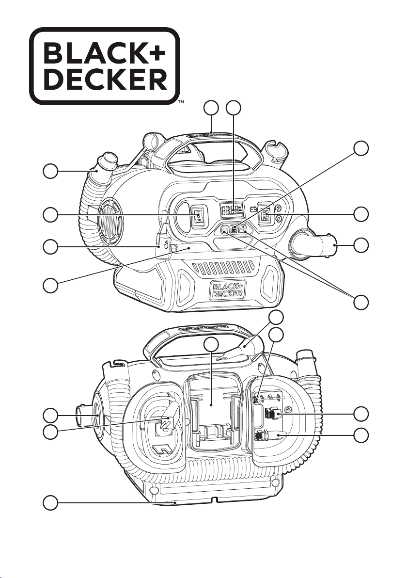
uTo remove the battery pack from the tool, press the
release button (22) and rmly pull the battery pack out of
the tool handle. Insert it into the charger as described in
the charger section of this manual.
Switching On (Fig. E, F)
Warning! Risk of Bursting. Do not leave unit running unat-
tended. Overinflation of tires and other items could result in
serious injury and property damage.
Note: When power is supplied to the inflator by 12v, 18v
battery, or 230V AC the LCD display will remain on for
approximately 10 minutes before the display shuts off/goes
into sleep mode.
This occurs when the unit is not operating.
To wake up the system, the user will need to push the
pressure mode / reset button (5) . At this time the LCD will
turn on and the inflator is ready for use.
uBefore switching your inflator on decided which power
source you will be using; 12V DC adapter, 230V AC plug
or a 18V battery pack.
uTo use the 12V DC adapter, or 18V battery pack press the
AC/DC power switch (1) located on the front of the unit to
DC.
uIf using the 12V DC cord, ,always fully extend the 12V DC
cord before each use.
uConnect the 12V DC adapter 14 into your vehicles 12V
DC accessory socket.
To use the 230V AC cord, press the AC/DC switch 1 located
on the front of the unit to AC.
uIf using the 230V AC cord 13 , always fully extend the
cord before each use.
uConnect the 230V AC plug 13 into either a wall outlet
or an approapriate sized extension cord that is
plugged into a wall outlet.
To turn on high-volume
The high-volume hose is meant to be used for objects that
hold large amounts of air, such as air mattresses, rafts, and
swimming pool floats.
Note: The high-volume mode DOES NOT have an auto
shut-off feature.
uAttach the high-volume hose (7) to the high volume pump
inator connection (12) as described in the “High
volume hose” section.
uInsert the high-volume hose (7) , or it’s tapered nozzle (8)
into the object being inated.
uPress the high-volume side of the mode power switch (2) ,
indicated by the air mattress symbol.
uTo turn off, push the power switch to the center position.
To turn on high-pressure
The high-pressure hose is meant to be used for objects that
need more air pressure, such as tires and basketballs.
uRemove the high-pressure hose (10) from the storage.
uAttach a nozzle as described in the “Universal valve
adapter” section.
uInsert the nozzle into the object being inated.
uPress the high-pressure side of the mode power switch
(2), indicated by the tire symbol.
uTo turn off, push the power switch to the center position.
Deate using the high-volume hose (Fig. H)
Warning! Beware of objects being ejected. When deflating,
large amounts of air will exit the high volume pump inflator
connection (12) . Ensure the universal valve adapter is not
pointed at anyone or anything.
uRemove the high-volume hose (7) from the storage
location.
uLine up the hose end (23) with the high-volume pump
deate connection (11) . Then, rmly slide in the hose so it
is securly in place.
uInsert the hose, or it’s tapered nozzle (8) into the object
being deated.
uPress the high-volume side of the mode power switch (2),
as shown in gure G, indicated by the air mattress symbol.
uTo turn off, push the power switch to the center position.
uTo remove the hose, twist the hose clockwise and slide
hose off.
Setting the automatic shut-off pressure
Note: The LCD will only show inflation pressures when the
inflator is being used. In both inflation and pump mode the
unit will show battery status.
uTo switch between the different units (psi, bar or kPa),
press the pressure mode button (5) until the required
units are displayed.
uPress the - or + pressure setting buttons (4) until the
required pressure is displayed.
uAfter 3 seconds the display will ash and return to a
reading of “0.0”. This is normal.
uConnect the universal valve adaptor and accessories,
if required, to the item to be inated, making sure that
the lever of the valve adaptor is in the down position to
lock it in place.
uTo start the inator press the mode power switch (2) ,
towards the side of the tire symbol.
uWhen the item to be inated has reached the preset
value the unit will automatically turn off. NOTE: You
may notice the actual pressure reading may drop after a
couple of seconds. This is normal.
uTo stop the inator at any time, press the main power
button back to the center position.
Note: If the AC/DC power switch is turned off, all settings
will be lost and will need to be reentered. This is a safety
feature to prevent the risk of items over inflating.

89
8
ENGLISH (Original instructions)
Using the inator as a pressure gauge
uConnect the universal valve adaptor (9) to the item to be
checked.
uPress the mode power switch (2) , on the side of the tyre
symbol.
uThe LCD will display the item’s pressure.
uAfter checking, press the mode power switch (2) back to
the center position and return the air hose to the storage
location.
Maintenance
Your BLACK+DECKER cordless appliance has been designed
to operate over a long period of time with a minimum of main-
tenance. Continuous satisfactory operation depends upon
proper tool care and regular cleaning.
Warning! Before performing any maintenance on cordless
appliances:
uRun the battery down completely if it is integral and then
switch off.
uUnplug the charger before cleaning it. Your charger does
not require any maintenance apart from regular cleaning.
uRegularly clean the ventilation slots in your appliance/
charger using a soft brush or dry cloth.
uRegularly clean the motor housing using a damp cloth. Do
not use any abrasive or solvent-based cleaner.
Protecting the environment
ZSeparate collection. Products and batteries
marked with this symbol must not be disposed of
with normal household waste.
Products and batteries contain materials that can be recov-
ered or recycled reducing the demand for raw materials.
Please recycle electrical products and batteries according to
local provisions.
Further information is available at
www.2helpU.com
Technical Data
BDCINF18
Voltage 18V
Weight 2.0Kg (Excluding Battery)
Class ll
Battery* BL1318
Voltage Vdc 18
Capacity Ah 1.3
Type Li-lon
Battery* BL1518
Voltage Vdc 18
Capacity Ah 1.5
Type Li-lon
Battery* BL2018
Voltage Vdc 18
Capacity Ah 2.0
Type Li-lon
Battery* BL4018
Voltage Vdc 18
Capacity Ah 4.0
Type Li-lon
Battery* BL1554
Voltage Vdc 18
Capacity mAh 2500
Type Li-lon
Battery* BL2554
Voltage Vdc 18
Capacity mAh 2500
Type Li-lon
Alternative
Bluetooth
Battery
pack*
BL1518ST BL2018ST
Voltage Vdc 18 18
Capacity Ah 1.5 2
Type Li-lon Li-lon
Charger*SSC-250040X
Input voltage VAC 230
Output
voltage VDC 8 - 20
Current
mA
400
* Not supplied with unit

89
Australia & New Zealand
StStanley Black & Decker
www.blackanddecker.com.au
www.blackanddecker.co.nz
Tel.1800 338 002 (Aust) or Tel. 0800 339 258 (NZ)

10 11

10 11

N519692 10/2017
Other manuals for BDCINF18
1
Table of contents
Popular Compressor manuals by other brands

Power Fist
Power Fist 8885600 instructions

mycom
mycom 3225**C Series instruction manual

AirMan
AirMan 55-001 user manual

Coltri Compressors
Coltri Compressors MCH-5 EVO CNG Use and maintenance manual

Harbor Freight Tools
Harbor Freight Tools Pittsburgh Automotive 43753 user manual

Luna
Luna ACD1.5-24OL manual

Parkside
Parkside PKZ 180 B2 Translation of the original instructions

Rothenberger
Rothenberger ROPULS Instructions for use

Pittsburgh
Pittsburgh 3980 Assembly and operating instructions

Schneider Airsystems
Schneider Airsystems PEM 500-15-50 B Original operating manual

PLASMATECH
PLASMATECH SHARK 25 Operator's manual

Tecumseh
Tecumseh AEA4440YXA Service Data Book