Black Diamond Equipment 20808 Manual

Extreme Networks, Inc.
3585 Monroe Street
Santa Clara, California 95051
(888) 257-3000
(408) 579-2800
http://www.extremenetworks.com
BlackDiamond®20808 Switch
Hardware Installation Guide
Published March 2009
Part number: 126002-00 Rev. 01

BlackDiamond 20808 Switch Hardware Installation Guide
2
AccessAdapt, Alpine, Altitude, BlackDiamond, EPICenter, Essentials, Ethernet Everywhere, Extreme Enabled,
Extreme Ethernet Everywhere, Extreme Networks, Extreme Standby Router Protocol, Extreme Turbodrive, Extreme
Velocity, ExtremeWare, ExtremeWorks, ExtremeXOS, Go Purple Extreme Solution, ScreenPlay, Sentriant,
ServiceWatch, Summit, SummitStack, Triumph, Unified Access Architecture, Unified Access RF Manager, UniStack,
the Extreme Networks logo, the Alpine logo, the BlackDiamond logo, the Extreme Turbodrive logo, the Summit
logos, and the Powered by ExtremeXOS logo are trademarks or registered trademarks of Extreme Networks, Inc. or
its subsidiaries in the United States and/or other countries.
sFlow is a registered trademark of InMon Corporation.
Specifications are subject to change without notice.
All other registered trademarks, trademarks, and service marks are property of their respective owners.
© 2009 Extreme Networks, Inc. All Rights Reserved.

BlackDiamond 20808 Switch Hardware Installation Guide 3
Table of Contents
Preface........................................................................................................................................... 7
About this Guide .........................................................................................................................7
Conventions................................................................................................................................7
Related Publications ...................................................................................................................8
Part 1: About the BlackDiamond 20808 Switch
Chapter 1: About the BlackDiamond 20808 Switch ......................................................................... 13
Overview of the BlackDiamond 20808 Switch..............................................................................13
BlackDiamond 20808 Chassis ...................................................................................................13
Chapter 2: BlackDiamond 20808 Switch Modules........................................................................... 17
Overview of the BlackDiamond 20808 Modules ...........................................................................17
Management Modules................................................................................................................17
Redundant Management Module Activity...............................................................................18
Features of the Management Module.....................................................................................18
Management Module LEDs...................................................................................................20
Switch Fabric Module................................................................................................................21
I/O Modules..............................................................................................................................21
BlackDiamond GM-40XA and GM-40XB I/O Modules ..............................................................22
BlackDiamond XM-8XB Module ............................................................................................23
I/O Module LEDs.................................................................................................................24
Chapter 3: BlackDiamond 20808 Power Supplies ........................................................................... 25
Overview of the BlackDiamond 20808 Power Supplies .................................................................25
AC Power Supply.......................................................................................................................25
LEDs..................................................................................................................................26
Fuse ..................................................................................................................................27
Power Supply Cords.............................................................................................................27
DC Power Supply ......................................................................................................................27
LEDs..................................................................................................................................28
Fuse ..................................................................................................................................28
Part 2: Installing the BlackDiamond 20808 Switch
Chapter 4: Site Preparation............................................................................................................ 31
Planning Your Site ....................................................................................................................31
Meeting Site Requirements ........................................................................................................32
Operating Environment Requirements ...................................................................................32
Building and Electrical Codes.........................................................................................32
Wiring Closet Considerations ..........................................................................................33
Electrostatic Discharge ..................................................................................................33
Humidity ......................................................................................................................33

Table of Contents
BlackDiamond 20808 Switch Hardware Installation Guide
4
Temperature .................................................................................................................34
Chassis Airflow Requirements.........................................................................................34
Space Requirements for the Switch.................................................................................35
Rack Specifications and Recommendations ...........................................................................36
Mechanical Recommendations for the Rack .....................................................................36
Protective Grounding for the Rack...................................................................................36
Meeting Power Requirements .....................................................................................................37
Power Supply Requirements.................................................................................................37
AC Power Cord Requirements ...............................................................................................38
Replacing the Power Cord ..............................................................................................39
Uninterruptible Power Supply Requirements ..........................................................................39
Selecting a UPS ............................................................................................................39
Calculating Volt-Amperage Requirements.........................................................................40
UPS Transition Time .....................................................................................................40
Evaluating and Meeting Cable Requirements ...............................................................................40
Cabling Standards ...............................................................................................................40
Cable Labeling and Record Keeping......................................................................................40
Installing Cable...................................................................................................................41
Fiber Optic Cable ..........................................................................................................42
Cable Distances ............................................................................................................43
RJ-45 Connector Jackets .....................................................................................................44
Radio Frequency Interference...............................................................................................44
Applicable Industry Standards....................................................................................................45
Chapter 5: Installing the BlackDiamond 20808 Chassis................................................................... 47
Unpacking................................................................................................................................47
Pre-Installation Requirements ....................................................................................................49
Front-Mounting a BlackDiamond 20808 Chassis..........................................................................49
Mid-Mounting a BlackDiamond 20808 Chassis............................................................................52
Attaching the PSU Air Baffles ....................................................................................................54
Grounding the BlackDiamond 20808 Chassis ..............................................................................55
Chapter 6: Installing Power Supplies in the BlackDiamond 20808 Switch ........................................ 57
Installing a 2400 W AC Power Supply Unit (PSU) ........................................................................57
Pre-Installation Requirements ..............................................................................................57
Installing an AC Power Supply ..............................................................................................58
Connecting Power ...............................................................................................................60
Using the Wire-Style Power Cord Retainer........................................................................60
Using the Clamp-Style Power Cord Retainer .....................................................................61
Removing an Extreme Networks 2400 W AC PSU.........................................................................63
Installing a 1900 W DC Power Supply.........................................................................................64
Required Tools and Materials ...............................................................................................64
Installation Summary...........................................................................................................64
Preparing the Cables ...........................................................................................................65
Installing the Power Supply..................................................................................................65
Connecting the Ground Cable ...............................................................................................68
Connecting the PSU to the DC Source Voltage .......................................................................69
Removing an Extreme Networks 1900 W DC PSU ........................................................................70
Installing a PSU Blank Slot Cover ...............................................................................................71

Table of Contents
BlackDiamond 20808 Switch Hardware Installation Guide 5
Chapter 7: Installing the BlackDiamond 20808 Modules ................................................................. 73
Required Tools..........................................................................................................................73
Installing Management Modules and I/O Modules.........................................................................74
Removing an I/O Module or Management Module .........................................................................77
Installing I/O or Management Module Blanks ...............................................................................80
Installing Switch Fabric Modules ................................................................................................81
Removing a Switch Fabric Module ..............................................................................................83
Installing Switch Fabric Module Blanks.......................................................................................85
Part 3: Maintenance Procedures
Chapter 8: Packing the BlackDiamond 20808 Chassis for Shipping ................................................. 89
Required Tools and Materials .....................................................................................................89
Removing the Chassis from the Rack ..........................................................................................89
Assembling the Shipping Container.............................................................................................90
Chapter 9: Cable Management Accessories .................................................................................... 91
About BlackDiamond Cable Management ....................................................................................91
Installing the BlackDiamond Cable Manager ................................................................................91
Using the Cable Holders and Cable Clips.....................................................................................96
Connecting Cable Holders ....................................................................................................97
Connecting Cable Clips ........................................................................................................98
Chapter 10: Replacing Ventilation and Airflow Components ........................................................... 101
Required Tools........................................................................................................................101
Replacing a Fan Tray...............................................................................................................101
Replacing the Front Fan Tray..............................................................................................101
Replacing the Rear Fan Tray ..............................................................................................103
Replacing a Chassis Air Filter ...................................................................................................105
Required Tools..................................................................................................................105
Replacing the Air Filter......................................................................................................105
Replacing an Air Filter in an XFM-1 Switch Fabric Module ..........................................................107
Replacing a PSU Air Baffle ......................................................................................................108
Part 4: Appendices
Appendix A: Safety Information .................................................................................................... 113
Considerations Before Installing ...............................................................................................113
Installing Power Supply Units...................................................................................................114
Maintenance Safety.................................................................................................................114
General Safety Precautions ......................................................................................................115
Cable Routing for LAN Systems ..........................................................................................115
Selecting Power Supply Cords ..................................................................................................116
Battery Replacement and Disposal............................................................................................117
Fiber Optic Ports—Optical Safety .............................................................................................117
GBIC, SFP (Mini-GBIC), XENPAK, and XFP Regulatory Compliance .......................................118

Table of Contents
BlackDiamond 20808 Switch Hardware Installation Guide
6
Appendix B: Technical Specifications .......................................................................................... 125
BlackDiamond 20808 Switch Specifications .............................................................................125
Power Supply Specifications ....................................................................................................127
Connector Pinouts...................................................................................................................128
Index .......................................................................................................................................... 131

BlackDiamond 20808 Switch Hardware Installation Guide 7
Preface
This preface provides an overview of this guide, describes guide conventions, and lists other
publications that might be useful.
WARNING!
Only trained service personnel should perform service to Extreme Networks switches and their components. Before
installing or removing any components of the system, or before carrying out any maintenance procedures, you must
thoroughly read the safety information provided in Appendix A of this guide. Failure to follow this safety information
can lead to personal injury or damage to the equipment.
About this Guide
This guide provides the instructions and supporting information needed to install the Extreme
Networks® BlackDiamond®20808 switch. The guide provides information about site preparation,
switch hardware features, and switch operation.
This guide is intended for use by network administrators responsible for installing and setting up
network equipment. It assumes a basic working knowledge of:
●Local area networks (LANs)
●Ethernet concepts
●Ethernet switching and bridging concepts
●Routing concepts
●Simple Network Management Protocol (SNMP)
See the ExtremeXOS 12.2 Concepts Guide and the ExtremeXOS 12.2 Command Reference Guide for
information about configuring Extreme Networks BlackDiamond 20808 switches.
NOTE
If the information in the installation note or release note shipped with your Extreme Networks switch differs from the
information in this guide, follow the installation or release note.
Conventions
Table 1 and Table 2 list conventions used in Extreme Networks documentation.

Preface
BlackDiamond 20808 Switch Hardware Installation Guide
8
Related Publications
The Extreme Networks ExtremeXOS®switch documentation set includes:
●BlackDiamond 20808 Switch Hardware Installation Guide (this guide)
●
ExtremeXOS 12.2 Concepts Guide
●
ExtremeXOS 12.2 Command Reference Guide
●
ExtremeXOS 12.2 Release Notes
●
BlackDiamond 8800 Series Switches Hardware Installation Guide
●
BlackDiamond 10808 Switch Hardware Installation Guide
●
BlackDiamond 12800 Series Switches Hardware Installation Guide
●
Summit Family Switches Hardware Installation Guide
●
Extreme Networks Pluggable Interfaces Hardware Installation Guide
Documentation for Extreme Networks products is available from the Extreme Networks website at the
following location:
http://www.extremenetworks.com/services/documentation
Table 1: Notice Icons
Icon Notice Type Alerts you to...
Note Important features or instructions.
Caution Risk of personal injury, system damage, or loss of data.
Warning Risk of severe personal injury.
Table 2: Text Conventions
Convention Description
Screen displays This typeface represents information as it appears on the screen, or command
syntax.
The words “enter”
and “type”
When you see the word “enter” in this guide, you must type something, and then
press the Return or Enter key. Do not press the Return or Enter key when an
instruction simply says “type.”
[Key] names Key names appear in text in one of two ways:
• Referenced by their labels, such as “the Return key” or “the Escape key”
• Written with brackets, such as [Return] or [Esc]
If you must press two or more keys simultaneously, the key names are linked with a
plus sign (+). Example:
Press [Ctrl]+[Alt]+[Del].
Words in italicized type Italics emphasize a point of information or denote new terms at the place where
they are defined in the text. Italics also indicate titles of books and other
publications.

Related Publications
BlackDiamond 20808 Switch Hardware Installation Guide 9
You can select and download the following Extreme Networks documentation from the Documentation
Overview page:
●Software user guides
●Hardware user guides
Archived user guides for software are available at:
http://www.extremenetworks.com/services/documentation/swuserguides.asp
Archived installation guides for hardware are available at:
http://www.extremenetworks.com/services/documentation/hwuserguides.asp

Preface
BlackDiamond 20808 Switch Hardware Installation Guide
10

1About the BlackDiamond 20808 Switch


BlackDiamond 20808 Switch Hardware Installation Guide 13
1About the BlackDiamond 20808 Switch
This chapter includes the following sections:
●Overview of the BlackDiamond 20808 Switch on page 13
●BlackDiamond 20808 Chassis on page 13
For information about the I/O modules, management modules (MMs), and switch fabric modules
(XFMs) for the BlackDiamond 20808 switch, see Chapter 2, “BlackDiamond 20808 Switch Modules.”.
For information about installing the BlackDiamond 20808 switch, see Chapter 3, “Installing the
BlackDiamond 20808 Chassis.”.
Overview of the BlackDiamond 20808 Switch
The BlackDiamond switches are chassis-based, Ethernet service core switches designed for core
applications. For more information about configuring a BlackDiamond switch, see the ExtremeXOS 12.0
Concepts Guide and the ExtremeXOS 12.0 Command Reference Guide.
The features of these switches include:
●I/O modules that are hot-swappable and include Gigabit Ethernet fiber ports (SFP), or 10-Gigabit
Ethernet ports (XFP)
●Up to 64 line-rate 10- Gigabit Ethernet ports in one chassis
●Redundant management modules that provide the CPU control subsystem
●Redundant switch fabric modules that provide the active switching fabric
●Redundant, load-sharing, hot-swappable power supplies
●Redundant field-replaceable, hot-swappable fan trays
●Auto-negotiation for half-duplex or full-duplex operation on 10/100/1000 Mbps ports
●Load sharing on multiple ports
●120 Gbps switch fabric capacity per I/O module
BlackDiamond 20808 Chassis
The BlackDiamond 20808 switch chassis has the following physical features:
●Height of 14.5 RU, allowing three switches to be installed in a 7-foot rack
●Optional mid-mount brackets for flexibility in rack positioning
●Ten vertical module slots in the front:
■Two dedicated management module slots, labeled A and B
■Eight I/O module slots, labeled 1 through 8
●Five horizontal chassis slots in the back for switch fabric modules
About the BlackDiamond 20808 Switch
BlackDiamond 20808 Switch Hardware Installation Guide
14
●Five bays for redundant AC or DC power supplies, accessible from the back
●Two fan trays:
■One under the front card cage and accessible from the front
■One above the switch fabric modules and accessible from the back
●Two connectors for an ESD-preventive wrist strap:
■One at the top right corner of the front panel
■One above the right side of the switch fabric modules
●Air filters for the chassis air intake and for the switch fabric modules
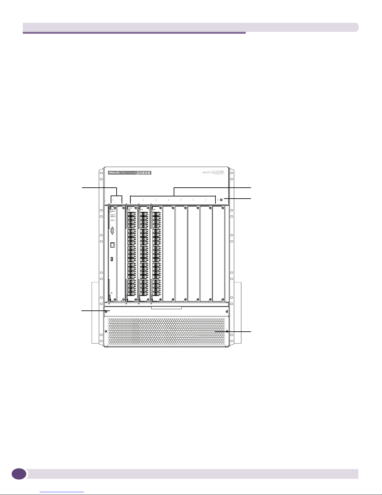
Figure 1 shows the front of a BlackDiamond 20808 chassis equipped with management modules and
I/O modules.
Figure 1: Front of the BlackDiamond 20808 Chassis
The front of the chassis provides access to:
●Card cage for the management modules and I/O modules
●Air intake vent with filter
●Fan tray with 12 fans
●Connection point for ESD-preventive strap
BD_223
ESD jack
Management
modules
Fan tray
I/O modules
Air intake

BlackDiamond 20808 Chassis
BlackDiamond 20808 Switch Hardware Installation Guide 15
Figure 2 shows the back of the BlackDiamond 20808 chassis.
Figure 2: Back of the BlackDiamond 20808 Chassis
The back of the BlackDiamond 20808 chassis provides access to:
●Five installation bays for AC or DC power supplies
●Five horizontal slots for switch fabric modules
●Fan tray with 12 fans
●Chassis cooling air exhaust vent
●Connection point for ESD-preventive strap
●Attachment point for optional chassis ground
●Airflow baffles for power supply ventilation
●Chassis serial number
●Ethernet MAC address of the switch
●Symbols of safety certification
BD_213
Chassis ventilation
exhaust
ESD jack
Switch fabric
modules
Fan tray
Power supplies
Chassis
ground point
Power supply airflow baffles

About the BlackDiamond 20808 Switch
BlackDiamond 20808 Switch Hardware Installation Guide
16

BlackDiamond 20808 Switch Hardware Installation Guide 17
2BlackDiamond 20808 Switch Modules
This chapter includes the following sections:
●Overview of the BlackDiamond 20808 Modules on page 17
●Management Modules on page 17
●Switch Fabric Module on page 21
●I/O Modules on page 21
Overview of the BlackDiamond 20808 Modules
Modules for the BlackDiamond 20808 switch include management modules, I/O modules, and switch
fabric modules.
Each module for the BlackDiamond 20808 switch consists of a printed circuit board mounted on a metal
panel that acts as the insertion vehicle in the switch. The module carrier also includes ejector/injector
levers and captive retaining screws at each end of the module front panel.
Table 3 lists the module types and models available for the BlackDiamond 20808 switch.
Management Modules
Two BlackDiamond 20808 management modules are available, the MM-Base and the MM-Adv. The
MM-Adv management modules support larger MAC address, IP route, and ACL capacity than the
MM-Base. Management modules provide the CPU control subsystem for the switch.
The BlackDiamond 20808 switch has two dedicated management module slots, labeled A and B. One
management module is required for switch operation; however, adding a second management module
increases system availability through redundancy. Each management module contains a temperature
sensor, nonvolatile random-access memory (NVRAM), and a real-time clock.
Table 3: Modules for the BlackDiamond 20808 Switch
Type Model
Management module MM-Base
MM-Adv
Switch fabric module XFM-1
I/O module XM-8XB
GM-40XB
GM-40XA

BlackDiamond 20808 Switch Modules
BlackDiamond 20808 Switch Hardware Installation Guide
18
Redundant Management Module Activity
The BlackDiamond 20808 switch can operate with a single management module installed, providing full
bandwidth with this single management module. When you install a second management module, one
of the management modules operates as the primary, and the other becomes the secondary or backup.
The primary management module is responsible for upper-layer protocol processing and system
management functions. The management modules in the BlackDiamond 20808 switch are not load
sharing. One management module handles packets while the other is idle.
When you save the switch configuration, it is saved to all management modules.
Selection of the primary management module occurs automatically. The following examples describe
the selection process:
●When a BlackDiamond 20808 switch boots with two management modules installed, the
management module in slot A becomes the primary.
If a switch is operating with one management module and a second management module is added
to the switch after it has been powered up, the added management module becomes the secondary.
Management modules that operate as secondary, or backup, management modules can be inserted
and removed without disrupting network services.
●If you remove the primary management module while the switch is operating, the secondary
management module performs a soft reset and then becomes the primary management module.
For example, if you have a BlackDiamond 20808 switch with a primary management module in
slot A and a secondary management module in slot B, and you remove the primary management
module from slot A, the secondary, or backup, management module in slot B becomes the primary.
Features of the Management Module
Figure 3 shows the front panel of the BlackDiamond management module.

Management Modules
BlackDiamond 20808 Switch Hardware Installation Guide 19
Figure 3: BlackDiamond 20808 Management Module
Management modules have the following features on the front panel:
●Console port—The DB-9 serial console port is used to connect a terminal, allowing you to perform
local management.
●Management port—The 10/100 Mbps Ethernet management port allows you to connect an Ethernet
cable directly from your laptop to the management port to view and locally manage the switch
configurations. This port can also be used to connect the system to a parallel management network
for administration.
●Reset button—Use the Reset button to reset the management module without removing the module
from the chassis.

BlackDiamond 20808 Switch Modules
BlackDiamond 20808 Switch Hardware Installation Guide
20
Management Module LEDs
LEDs on the management module (see Table 4) provide status information about the switch operation
and major chassis components.
Table 4: LEDs on the Management Module
Label/Function Color/State Meaning
SYS
System status
Green/blinking System has booted and is operating normally.
Off System is booting or is powered off.
MSTR
Master/backup status of
module
Green/steady This management module is the master in the
system.
Off This management module is not the master in the
system.
ENV
Environmental status
Green/steady The system is operating within the defined
operational limits.
Amber/steady The system is operating outside the defined
operational limits.
Off Environmental conditions for the system are unknown
or the management module is not the master.
ERR
Error
Green No critical errors are present.
Amber One or more critical errors are present.
Off This management module is the backup module.
FAN1:Loser (front) fan tray
FAN2:Upper (back) fan tray
NOTE: FAN3 and FAN4 are
not used.
Green/steady The indicated fan tray is installed and operating
within specification.
Amber/steady The indicated fan tray has an error condition. See the
system log for details
Off The indicated fan tray is not installed
PSU
Power supplies
Green/steady The power supplies are operating normally.
Amber/steady One or more power supplies have an error condition.
See the system log for details.
Off This management module is not receiving power.
PWR
State of the power/fan
controller on this module.
Green/blinking The power/fan controller is operating normally.
Amber/steady The module is booting but is not yet operational.
Amber/blinking The power/fan controller has an error condition. See
the system log for details.
Table of contents
Other Black Diamond Equipment Switch manuals

Popular Switch manuals by other brands

SMC Networks
SMC Networks SMC6224M Technical specifications

Aeotec
Aeotec ZWA003-S operating manual

TRENDnet
TRENDnet TK-209i Quick installation guide

Planet
Planet FGSW-2022VHP user manual

Avocent
Avocent AutoView 2000 AV2000BC AV2000BC Installer/user guide

Moxa Technologies
Moxa Technologies PT-7728 Series user manual

Intos Electronic
Intos Electronic inLine 35392I operating instructions

Cisco
Cisco Catalyst 3560-X-24T Technical specifications

Asante
Asante IntraCore IC3648 Specifications

Siemens
Siemens SIRIUS 3SE7310-1AE Series Original operating instructions

Edge-Core
Edge-Core DCS520 quick start guide

RGBLE
RGBLE S00203 user manual


