Black Magic Clutches DEFIANT X User manual

*** When disassembling the Defiant X Clutch Assembly for installation, make sure not lose the small
washer/shims from between the cover and flywheel. In addition to the large spacers there are
additional shims at each bolt/stud. These should be kept in place as the cover assembly has had the ring
height already set when purchasing a new compete unit or after coming back from servicing.
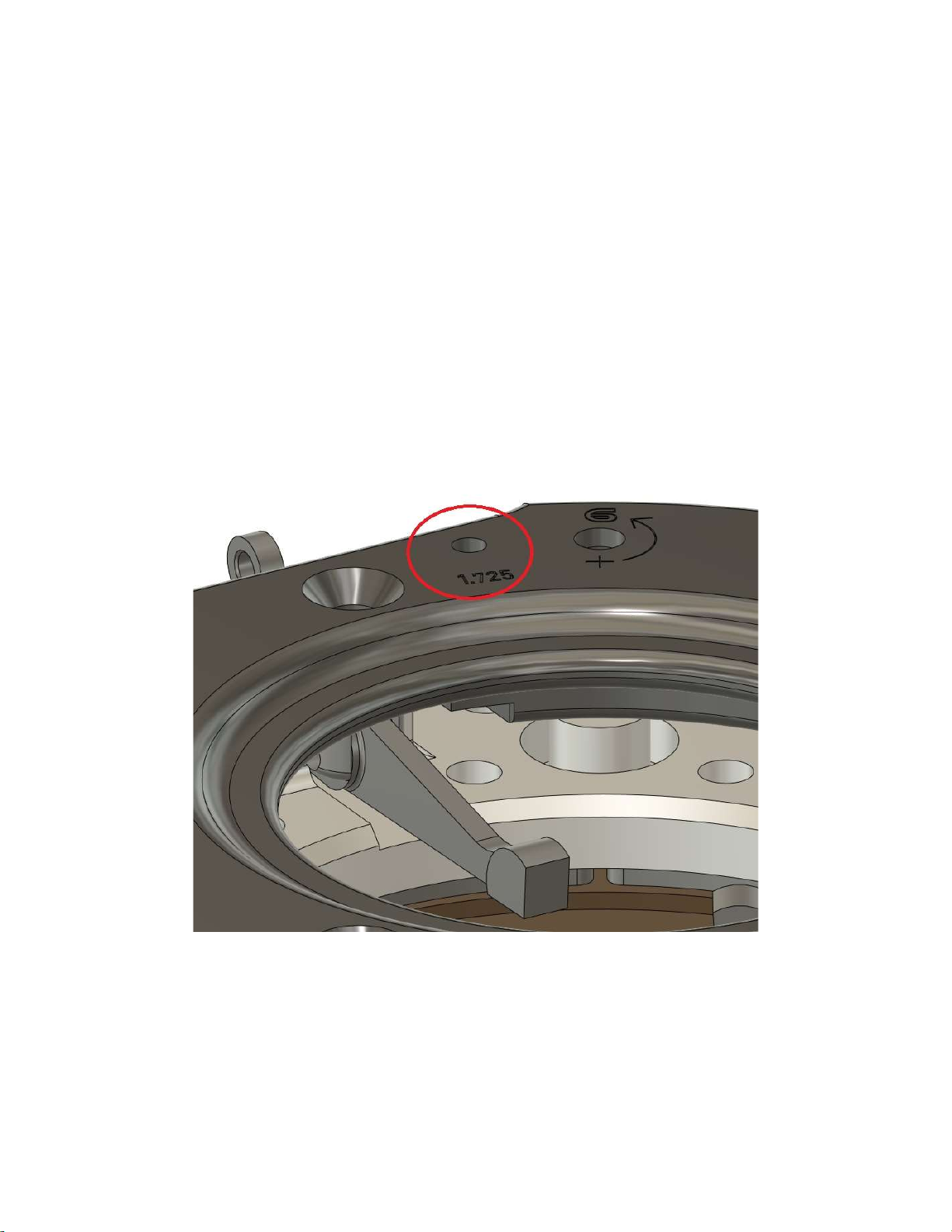
Ring Height
- Base/Standard ring height should be 1.725” (Pictured)
This is measured by using the tip of a set of dial calipers to measure through the hole in the
cover from the face of the cover down to the pressure plate.
- Ring Height can be adjusted by shimming between the cover and flywheel.
- This will change as the disc wears. We don’t recommend re-shimming to reset lever height until at
least a .030” change (.030” wear off the disc). The levers will move upward towards the bearing as the
ring height changes. You will lose approximately 12 lbs of base pressure with every .010” of disc
wear/ring height change.

Lever Height
- Standard Lever Height is set and measure two ways. Either from the tip of the lever to a straight
edge, or by measuring the gap between top of lever and the bottom edge of the cover. (Both
Pictured Below) There should never be more than a .007” variance in all three levers so that the
throwout bearing makes even contact and will ensure the same air gap at all three lever lug
locations around the full diameter of the clutch surface.
When Measuring to the lever tip with a straight edge,
place straight edge flat across the cover surface.
When Measuring this way levers can be set from .650 - .700”
When Measuring to the gap between lever and cover
When Measuring this way levers can be set from .280” - .330”
Adjusting Lever Height
- The Defiant utilizes precision machined yokes, that have minimal variance in overall height. As it
is rarely needed to adjust lever height except after a rebuild/servicing we have returned to the
shim style method of adjusting to give the cover a flat profile across the top. By using flat shim
stock we can adjust the lever height up or down. The shims are placed between the yoke and
bottom of the cover at each lever location. The Defiant X features Dyno tested and designed levers
that allow the use of conventional counter weight with specific applied pressure information
(provided below), with the added feature of “In-Board” counter weight holes located inside the
cover closer to the throwout bearing. In addition to lever height controlling the applied pressure
rate of the levers, we can control this much more effectively by utilizing in-board counter weight.
We work directly with customer’s choosing to use this feature. Mot commonly used in lower
hp/weight combinations with higher rpm.

Disc Options
- New units will feature either a .330” or .380” thick disc. This is selected at the time of order to
work with clearance options and overall use of the clutch.
- Most standard built units will come with a standard 5135 type compound.
- We work with customers on their specific combination on each clutch and in some cases suggest
a different disc material to lessen friction coefficient and allow for the use of more applied
pressure through base and counter weight offering a larger tuning window.
Common Disc Materials
5135 – Most Aggressive Compound
5050 – Medium (We rarely use this in drag racing)
5191 – Least Aggressive
Additional Black Magic Compound Options
BMC-850 - Approximately 15% Less Friction Coefficient as 5191,
Better Door Car Compound on Lower HP
BMC-PS1 – Approximately 7% less friction coefficient than standard 5191
Sintered Bronze – Approximately in the middle of 5135 and 5191, however will increase friction
coefficient as it sees an increase in temperature.
The disc should always be placed with the raised part of the hub towards the transmission and away
from the flywheel s seen below.

Specifications and Design Information
Spring Information / Base Pressure
- Free Length: 2.08”
- Rate of Pressure: 208 lbs per Inch or 52 lbs per 1/4 Inch
- Base Sheet Provided at 1/4 turn increments
- Maximum Turns: 7 Turns
- 360 lbs Total Pressure at Zero Turns (Standard 1.725” Ring Height)
- Cover to Flywheel Bolt/Stud Torque should be “snug” or approximately 30 ft/lbs
*** We don’t recommend more than 6.5 turns. If the adjuster backs completely out
of the aluminum adjusters the unit must be taken apart and the adjusters must be
rethreaded into the cups. Running the clutch with them fully backed out of the cups,
it will damage them.
Clockwise Removes Base / Counter Clockwise Adds Base.
To start turn all the way clockwise until fully loose.
Turn Counter Clockwise until you start to feel slight resistance. Start counting from there.
Counter Weight
- 1/4 Inch holes are located to the outside of the clutch unit to add counter weight.
- There are also “in-board” counter weight holes on the inside of the lever (towards the hub)
These holes can be used to slow the rate of applied pressure, but we recommend
consulting with Cale Aronson for exact tuning information.
- Attached is an Applied Pressure Sheet showing the applied pressure in Lbs, over every 100
rpm.
** Loctite should never be used on counter weight!!
Installation Notes:
When you receive a Defiant Assembly new or rebuilt from Black Magic Clutches, your ring height and
lever height will already be set. Simply remove the cover from the flywheel, install the flywheel onto
your crankshaft. Be careful to keep all shims located on the studs/bolts in place as this is what is used
to set your “Ring Height”. After installing your flywheel, reinstall your disc and cover assembly. Using
an alignment tool center the disc on the flywheel/pressure plate surface and install the nuts on the
studs/bolts. Evenly draw the cover down and if torqueing apply approximately 30 ft/lbs on cover nuts.
Upon receiving your clutch, get in touch with us for a starting point and any general procedure
questions!

** It’s easier to install with no turns of base as it will have the least pressure. Add base
pressure after installation.
Throwout Bearing: You should run a wide, flat faced bearing that covers the lever tips completely. If
needed, contact us for bearing options.
Free Travel: This is the distance between the throwout bearing and levers when clutch pedal is in the
up/non-engaged position. There should be .200” - .250” free travel between you throwout bearing
and levers. We recommend a stiff return spring to keep bearing way from levers. Bearing to lever
contact can reduce applied pressure and cause damage to the levers as well as premature wear and
excessive slippage.
Air Gap: This is the amount of clearance between the disc and either heat shield when the clutch is
depressed. Generally measured with a feeler gauge. We recommend between .045” minimum and
.075” maximum. You should have an adjustable positive/solid clutch pedal stop to set this properly.
This should be checked regularly as wear of the disc will effect it. Heat also will cause a variance as the
materials expand.
Two Step: Your two step/launch rev limiter should be set to turn on/off at the point the bearing
comes in contact with the levers and should stay on throughout the travel of the clutch cycle. Do not
tie this function to your line-lock.

Defiant X 10.00” 3 Lever Applied Counter Weight Pressure
GRAMS
lb per gram
15
18
21
24
27
30
33
36
3500
8.1 121.7 146.0 170.3 194.6 219.0 243.3 267.6 292.0
3600
9.1 135.9 163.1 190.3 217.4 244.6 271.8 299.0 326.2
3700
10.0 150.2 180.2 210.2 240.2 270.3 300.3 330.3 360.4
3800
11.0 164.4 197.3 230.2 263.0 295.9 328.8 361.7 394.6
3900
11.9 178.4 214.0 249.7 285.4 321.0 356.7 392.4 428.0
4000
12.8 192.2 230.6 269.0 307.4 345.9 384.3 422.7 461.2
4100
13.7 205.8 247.0 288.1 329.3 370.4 411.6 452.8 493.9
4200
14.6 219.2 263.0 306.8 350.6 394.5 438.3 482.1 526.0
4300
15.4 230.9 277.0 323.2 369.4 415.5 461.7 507.9 554.0
4400
16.3 243.9 292.7 341.5 390.2 439.0 487.8 536.6 585.4
4500
17.1 256.5 307.8 359.1 410.4 461.7 513.0 564.3 615.6
4600
18.2 272.7 327.2 381.8 436.3 490.9 545.4 599.9 654.5
4700
18.9 283.2 339.8 396.5 453.1 509.8 566.4 623.0 679.7
4800
19.8 296.7 356.0 415.4 474.7 534.1 593.4 652.7 712.1
4900
20.9 313.2 375.8 438.5 501.1 563.8 626.4 689.0 751.7
5000
21.5 322.7 387.2 451.7 516.2 580.8 645.3 709.8 774.4
5100
22.5 336.8 404.1 471.5 538.8 606.2 673.5 740.9 808.2
5200
23.4 351.5 421.7 492.0 562.3 632.6 702.9 773.2 843.5
5300
24.5 366.9 440.3 513.7 587.0 660.4 733.8 807.2 880.6
5400
25.4 380.3 456.3 532.4 608.4 684.5 760.5 836.6 912.6
5500
26.3 394.8 473.8 552.7 631.7 710.6 789.6 868.6 947.5
5600
27.1 407.1 488.5 569.9 651.4 732.8 814.2 895.6 977.0
5700
28.2 422.9 507.4 592.0 676.6 761.1 845.7 930.3 1014.8
5800
29.1 436.7 524.0 611.3 698.6 786.0 873.3 960.6 1048.0
5900
30.3 455.0 545.9 636.9 727.9 818.9 909.9 1000.9 1091.9
6000
31.1 466.4 559.6 652.9 746.2 839.4 932.7 1026.0 1119.2
6100
32.1 480.9 577.1 673.3 769.4 865.6 961.8 1058.0 1154.2
6200
33.4 500.4 600.5 700.6 800.6 900.7 1000.8 1100.9 1201.0
6300
35.0 525.6 630.7 735.8 841.0 946.1 1051.2 1156.3 1261.4
6400
36.0 540.2 648.2 756.2 864.2 972.3 1080.3 1188.3 1296.4
6500
37.5 562.1 674.5 786.9 899.3 1011.7 1124.1 1236.5 1348.9
6600
39.2 587.3 704.7 822.2 939.6 1057.1 1174.5 1292.0 1409.4
6700
40.2 602.7 723.2 843.8 964.3 1084.9 1205.4 1325.9 1446.5
6800
41.3 619.7 743.6 867.5 991.4 1115.4 1239.3 1363.2 1487.2
6900
43.1 646.1 775.3 904.5 1033.7 1162.9 1292.1 1421.3 1550.5
7000
44.8 672.3 806.8 941.2 1075.7 1210.1 1344.6 1479.1 1613.5
7100
46.5 697.1 836.5 975.9 1115.3 1254.7 1394.1 1533.5 1672.9
7200
48.4 726.0 871.2 1016.4 1161.6 1306.8 1452.0 1597.2 1742.4
7300
50.1 751.4 901.6 1051.9 1202.2 1352.4 1502.7 1653.0 1803.2
7400
52.0 779.7 935.6 1091.6 1247.5 1403.5 1559.4 1715.3 1871.3
7500
53.8 806.6 967.9 1129.2 1290.5 1451.8 1613.1 1774.4 1935.7
7600
55.6 833.7 1000.4 1167.2 1333.9 1500.7 1667.4 1834.1 2000.9
7700
57.3 858.9 1030.7 1202.5 1374.2 1546.0 1717.8 1889.6 2061.4
7800
59.1 886.7 1064.0 1241.3 1418.6 1596.0 1773.3 1950.6 2128.0
7900
60.8 911.9 1094.2 1276.6 1459.0 1641.3 1823.7 2006.1 2188.4
8000
62.7 940.1 1128.1 1316.1 1504.1 1692.1 1880.1 2068.1 2256.1

Applied Base Pressure (Per 1/4 Turn)
360 Lbs at Zero Turns
Turns Pressure
Turns Pressure
0.25 368.5 3.75 627.5
0.5 387 4 646
0.75 405.5 4.25 664.5
1 424 4.5 683
1.25 442.5 4.75 701.5
1.5 461 5 720
1.75 479.5 5.25 738.5
2 498 5.5 757
2.25 516.5 5.75 775.5
2.5 535 6 794
2.75 553.5 6.25 812.5
3 572 6.5 831
3.25 590.5 6.75 849.5
3.5 609 7 868
Black Magic Clutches / Aronson Motorsports
www.blackmagicclutches.com
Cale@BlackMagicClutches.com
816-390-0852
Table of contents
Popular Industrial Equipment manuals by other brands

Bomar
Bomar Individual 720.540 DGH operating instructions

Energy Recovery
Energy Recovery PX G1300 Installation and operation manual

MARTINS Industries
MARTINS Industries MIC-AUHD-52 manual

Panasonic
Panasonic ERJ C1 Series manual

ABB
ABB Power2 340-H44 Operation manual

Dungs
Dungs VDK 200 A S02 H2 Operation and assembly instructions


