Energy Recovery PX G1300 User manual
PX G1300™Energy Recovery
Device
Installation and Operation Manual

Page 2 of 13 ERI Document 80809-01
Risk of accidents.
Pressure Exchangers are pressurized machines and as such call for heightened caution/care in handling.
Improper assembly and use of the Pressure Exchanger can result in serious or fatal injury!
- To avoid serious injury or death, observe all safety instructions contained in these instructions
before assembly and before using the Pressure Exchanger! This will avoid misunderstandings and
prevent serious or fatal injury and damage!
- Never use the product improperly but only as recommended by this manual!
- Observe all product safety labels!
- Refer to local building codes for installation requirements!
Unauthorized changes and modifications to the product not covered by this manual are prohibited and
will void the warranty!
This instruction manual is a mandatory part of the product. It must be available to the personnel who
operate and maintain this product. It must be passed onto the end customer along with the unit in
which the pressure exchanger is installed.
Energy Recovery Inc.
1717 Doolittle Dr.
San Leandro, CA 94577
+1-510-483-7370
https://energyrecovery.com

Page 3 of 13 ERI Document 80809-01
Table of Contents
1. ABOUT THE PX G1300 DEVICE .................................................................................................................................4
2. SAFETY ......................................................................................................................................................................5
3. PRODUCT DESCRIPTION...........................................................................................................................................7
4. ELECTRICAL ...............................................................................................................................................................7
5. INSTALLATION ..........................................................................................................................................................9
1. OPERATION ............................................................................................................................................................10
2. MAINTENANCE .......................................................................................................................................................11
3. DIMENSIONS ..........................................................................................................................................................12
4. LEARNING AND CONTACTING ENERGY RECOVERY...............................................................................................13

Page 4 of 13 ERI Document 80809-01
1. ABOUT THE PX G1300 DEVICE
1.1. About this Manual
This manual contains instruction for the installation and operation of Energy Recovery, Inc. PX G1300 (PX G) energy
recovery devices for CO2 Refrigeration Systems. This information is provided to ensure the long life and safe
operation of your PX G energy recovery device. This manual is intended for use by personnel with training and
experience in the installation and operation of fluid handling systems. For additional information regarding using the
PX G device in CO2 Refrigeration Systems refer to Energy Recovery’s website: www.energyrecovery.com or contact
customer service.
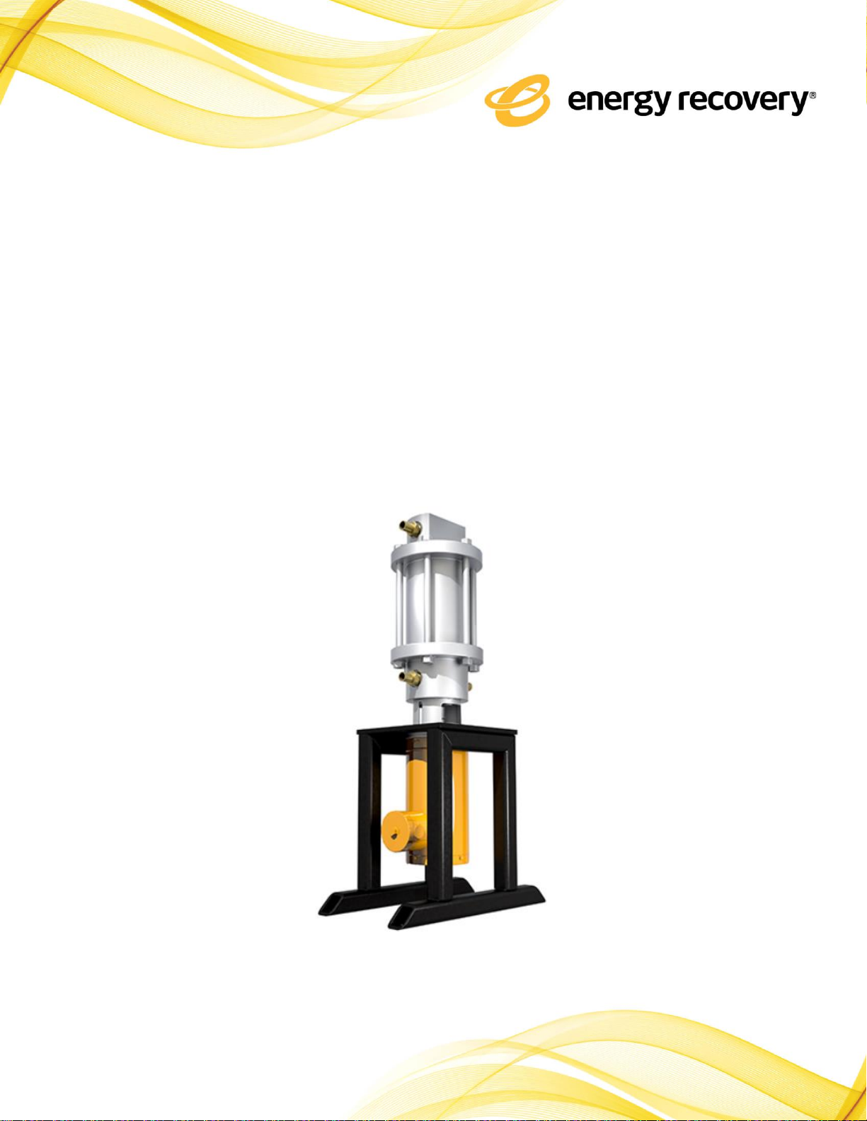
1.2 Device Basics
Energy Recovery’s new PX G1300 energy recovery device reduces the barriers to CO2 adoption in supermarkets in all
ambient temperatures. CO2 systems offer near-zero global warming potential (GWP) —a huge benefit as retailers
work to green their operations and comply with regulation to phase out HFCs. The PX G recovers lost energy and
lowers the electricity bill of CO2 systems. This improves the bottom line for supermarkets and reduces their carbon
footprint. By recycling pressure energy and returning it to the system, the PX G reduces energy consumption and
operating costs of CO2 refrigeration. The PX G works by expanding the refrigerant similar to a valve, but recovers the
energy of expansion and provides compression. This reduces the load on the compressors and the energy
consumption of the system.
1.3 Operational Limits
Successful operation of the PX G1300 energy recovery device requires observation of some basic operating
conditions and precautions. The PX G unit must be installed/operated in accordance with this manual and good
industrial practice to ensure safe operation and a long service life. Failure to observe these conditions and
precautions can result in reduced service life, damage to the equipment and/or harm to personnel. For operational
conditions, refer to the Technical Data Sheet of the product. Table 1 provides a summary of system performance
limits.
Page 5 of 13 ERI Document 80809-01
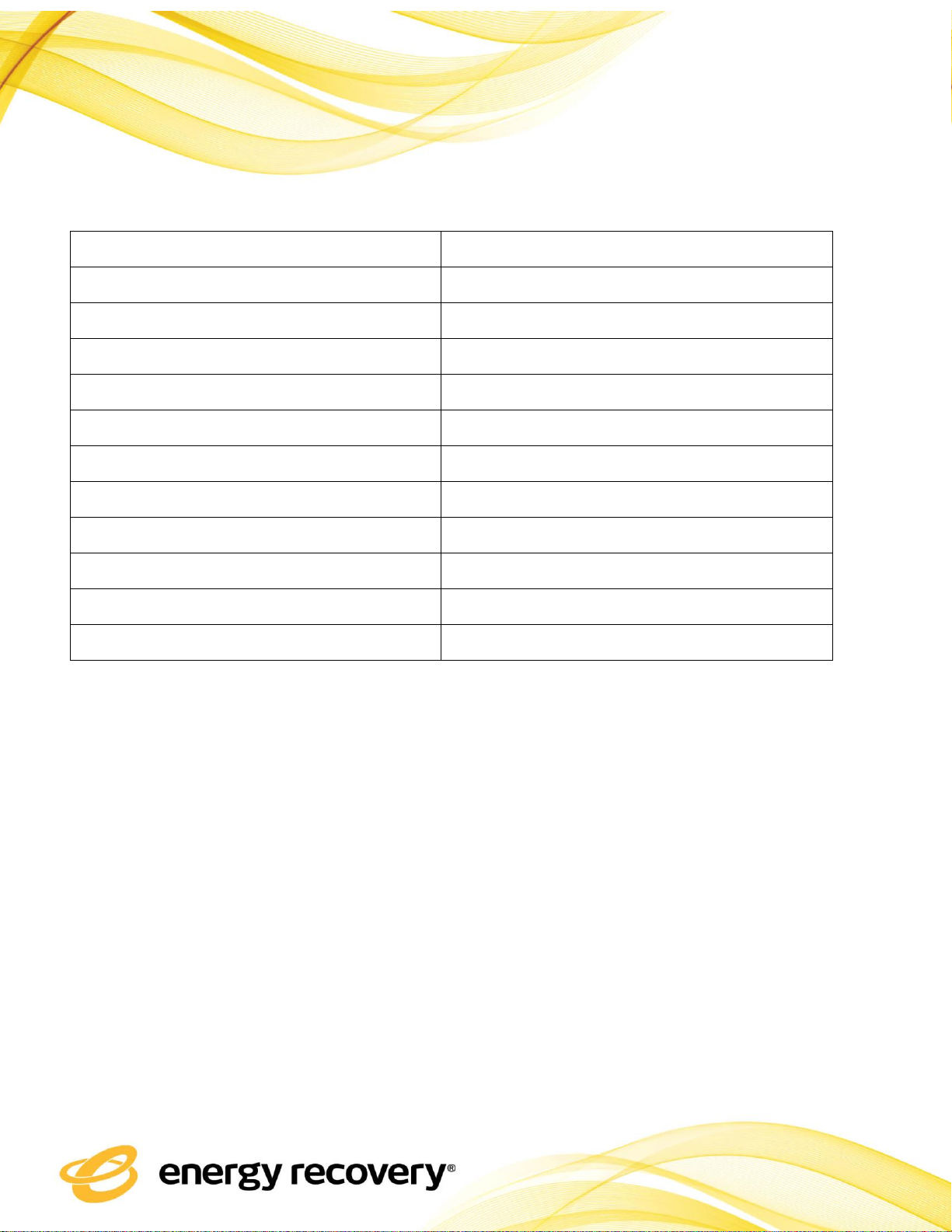
Table 1 –System Performance Limits
2. SAFETY
The PX G device is designed to provide safe and reliable service; however, it is used in a high-pressure industrial
process. Operations and maintenance personnel must follow the basic safety rules associated with high-pressure
equipment and CO2 refrigeration processes. Proper installation and maintenance of shutdown devices and over-
pressure and over-flow protection equipment are an essential part of any CO2 refrigeration system. Operation of
the PX G device outside of the designed operating range can result in damage and may be unsafe. The product is not
intended for use by persons (including children) with reduced physical, sensory or mental capabilities or lack of
experienced unless supervised or provided with instructions by a person responsible for their safety. Children
should be supervised to ensure that they do not play with the product.
Parameter
Operational Value Limits
Fluid
R-744 (CO2)
Operating Temperature
33°F-220°F (0.6-121°C)
Max. Temperature
220°F (104°C)
Minimum RPM
200
Maximum RPM
1600
Capacity Range
0.4 to 3.3 acfm (0.7 to 5.6 m3/hr)
Maximum Inlet Pressure (HP Side)
2030 psig (140 barg)
Maximum Inlet Pressure (LP Side)
700 psig (48.3 barg)
Minimum Outlet Pressure
500 psig (34.5 barg)
Maximum Power Consumption
0.5 kW
Refrigeration Capacity
60 kW to 150 kW

Page 6 of 13 ERI Document 80809-01
2.1. High Pressure Remains After Shutdown
The high-pressure section of a CO2 refrigeration system equipped with a PX G energy recovery device can remain
pressurized after shutdown. Pressure decreases as CO2 slowly flows through the hydrodynamic bearing of the PX G
unit. If more rapid system depressurization during shutdowns is required, the system should be designed with
accommodating valves and piping. Always make sure the CO2 system is fully depressurized before disconnecting any
piping or equipment.
2.2. Low Pressure Isolation and Over-Pressurization
If the low-pressure side of the PX G energy recovery device is isolated before the high-pressure side is depressurized,
the PX G unit or the low-pressure piping may be damaged by over-pressurization. High-pressure CO2 will seep
through the PX device’s hydrodynamic bearing to low-pressure regions in the PX G unit. To prevent this over-
pressurization scenario, use appropriate pressure relief valves, rupture disc and/or depressurization procedures.
Page 7 of 13 ERI Document 80809-01
3. PRODUCT DESCRIPTION
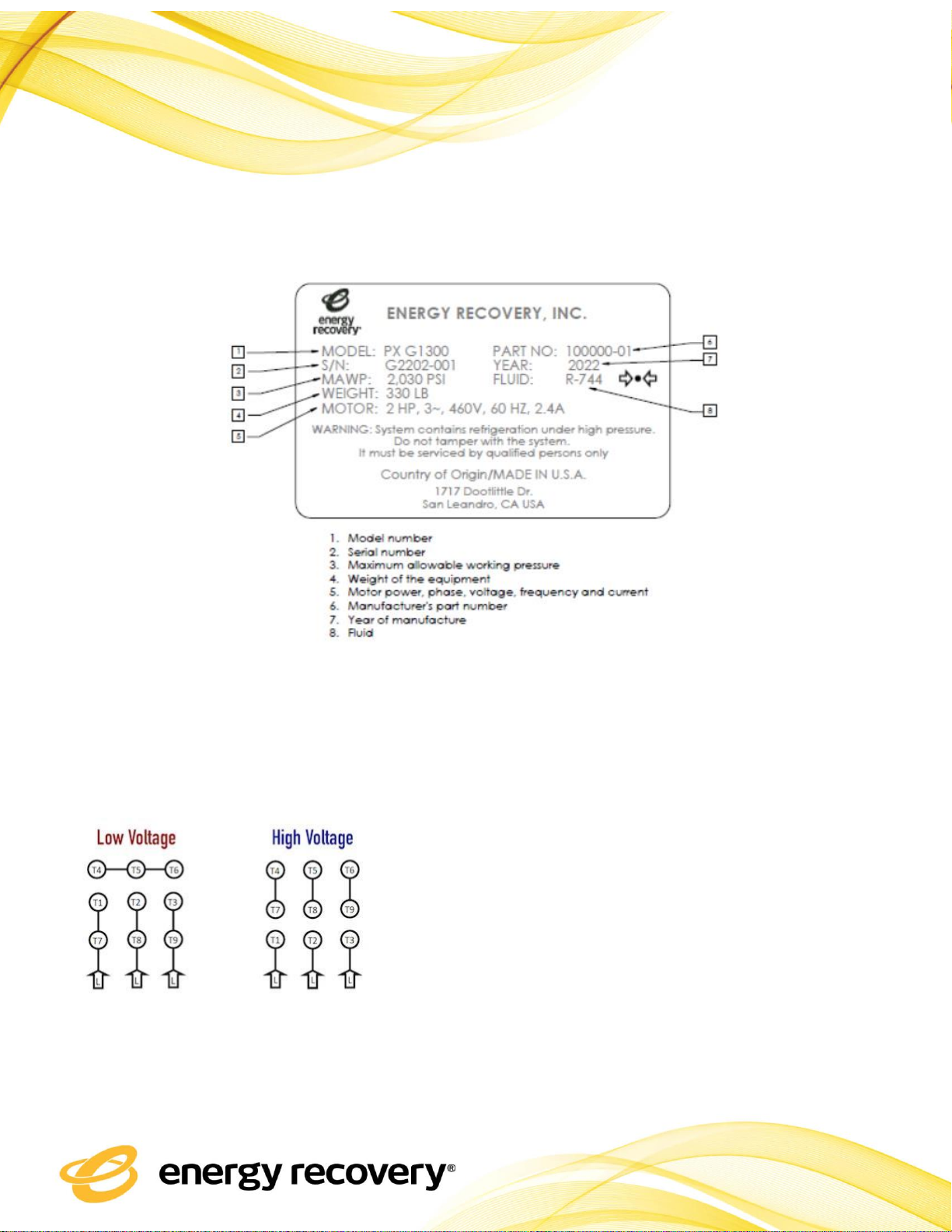
4. ELECTRICAL
4.1. Wiring Diagram
The appliance should be installed per national wiring regulations.
Page 8 of 13 ERI Document 80809-01

Page 9 of 13 ERI Document 80809-01
5. INSTALLATION
5.1. Installation
Each unit has four connections labeled HP IN, HP OUT, LP IN, and LP OUT.
HP IN is the high-pressure CO2 from gas cooler inlet.
HP OUT is the high-pressure CO2 Outlet
LP IN is the low-pressure CO2 flash gas inlet.
LP OUT is the low-pressure CO2 to refrigeration cases
The PX G unit must be supported by its bottom housing and not by the pipe fittings. Prevent the PX G unit from
supporting piping or manifolds. The PX G unit is supplied with a frame designed to be bolted to the rack.
Proper piping, piping support, and housing support must be employed to minimize external stresses on all pipe
fittings. Suitable flexible couplings should be used for joining fittings and piping. Use only water-soluble lubricants
such as glycerin on O-Rings and coupling gaskets; do not use grease. Please request dimensioned drawings of a PX G
device and a piping detail for use for piping, manifold, and support rack design.
Prior to installation of the PX G device, all associated piping should be thoroughly flushed to assure that no debris
enters and/or damages the PX G unit. Temporary installation of basket strainers at both inlets to the PX G device or
PX G device array can be used.
5.2. Set Up
The Pressure Exchanger requires a ceramic cartridge installed inside the housing to operate. Ensure there is
adequate clearance for cartridge installation and/or maintenance work necessary to be completed. ERI recommends
at least 4” of clearance around the Pressure Exchanger.

Page 10 of 13 ERI Document 80809-01
6. OPERATION
6.1. Start and Stop Procedures
The following procedures are general guidelines for the startup and shutdown of PX G unit systems. Procedure
details will vary by plant design. Contact Energy Recovery if your process design significantly differs from that shown
in Figure 1. Always ensure that the operating limits listed in Section 1.3 are followed.
6.2. Start Up
-Ensure that the Pressure Exchanger is connected and all communications are working with the rack
-The if there are any manual valves, ensure the valves are in the open position prior to starting up the
Pressure Exchanger
-The Pressure Exchanger is automated and will kick on when the refrigeration rack sends the signal to the
controller.
-Stand by to ensure the Pressure Exchanger begins spinning.
-During this moment, all automatically actuated valves should be open.
6.3. High and Low Pressure Flow Rates
The high-pressure flow into the PX unit is set by a high pressure CO2 compressor controlled by a variable frequency
drive (VFD) and verified with a mass flow meter. The flow rate of the high-pressure CO2 out of the PX unit is also
measured with a mass flow meter. The high-pressure CO2 exiting the PX equals the high pressure flow entering the
PX unit minus the fluid required to lubricate the bearings.
The low-pressure flow through the PX unit is regulated by either a VFD-controlled low pressure booster compressor
or a flow control valve, depending on the configuration of the system. Low-pressure flows into and out of the PX are
measured using separate mass flow meters. The low-pressure CO2 exiting the PX equals the low pressure flow
entering the PX unit plus the fluid required to lubricate the bearings.
6.4. Purge Air

Page 11 of 13 ERI Document 80809-01
Entrained or trapped air or other gases must always be purged from the CO2 system before pressurizing the system.
Entrained air in a pressurized system can result in damage to the PX G unit. Prior to pressurizing the CO2 system
vent or flush for sufficient time to allow for the removal of all air from the CO2 system.
7. MAINTENANCE
7.1. Preparation
If maintenance is required for the Pressure Exchanger:
-Ensure the Pressure Exchanger is not running and locked out from running
-Ensure the Pressure Exchanger is bypassed from the continuously operating rack
-Bleed off the Pressure Exchanger side of the system before any maintenance is performed
7.2. Service Intervals
This unit does not require maintenance. For optimal operating safety and extended service life, it is recommended
to carry out the following necessary checks every 6 months:
-Check the Pressure Exchanger Housing for visible evidence of leaks
-Check Nuts/Bolts on the Pressure Exchanger Housing
-Check Nuts/Bolts that attach the motor/housing
-Check Pressures/Temperatures
7.3. Spare Parts
-Available spare parts and accessories are available at Energy Recovery Inc. Contact Energy Recovery for any
spare parts and work to be completed.
-
7.4. Leaks from Pressure Exchanger
-If a leak is visible from the Pressure Exchanger, the PX should automatically shut off
-Ensure the PX is shut down and shut in (bypassed)
-If CO2 is detected near the motor to housing mating area, it is likely the shaft seal has been damaged.
oContact ERI to notify that maintenance is required to replace the damaged shaft seal.

Page 12 of 13 ERI Document 80809-01
8. DIMENSIONS

Page 13 of 13 ERI Document 80809-01
9. LEARNING AND CONTACTING ENERGY RECOVERY
More information about PX G1300 technology is available on Energy Recovery’s website: www.energyrecovery.com,
Recovery at +1-510-483-7370
Table of contents
Other Energy Recovery Industrial Equipment manuals


