Dynatech PR-2000 UD Specification sheet

PARACAÍDAS PROGRESIVO DYNATECH/
DYNATECH PROGRESSIVE SAFETY GEAR/
PARACHUTE À PRISE AMORTIE DYNATECH/
BREMSFANGVORRICHTUNG DYNATECH/
PR-2000-UD
INSTRUCCIONES DE USO Y MANUTENCIÓN/
INSTRUCTIONS FOR USE AND MAINTENANCE/
INSTRUCTIONS D’USAGE ET ENTRETIEN/
GEBRAUCHS- UND WARTUNGSANLEITUNG/

INSTRUCTIONS : PR-2000-UD Cod : DYN 07.01.10
Date : 20/10/2020 Revision : 10
1
REVISION
10
DATE
20/10/2020
PRODUCED BY / APPROVED BY
J.A. Torrubia/O.Lacámara
SECTION DESCRIPTION
EFFECTIVE DATE OF
CHANGE
4.3
Explanatory note is added
Not applicable
7
Annex section is added
Not applicable
REVISION
09
DATE
17/07/2017
PRODUCED BY / APPROVED BY
P. Hernandez/O. Lacámara
SECTION DESCRIPTION
EFFECTIVE DATE OF
CHANGE
2.2
Paragraph content modified
Not applicable
REVISION
09
DATE
15/04/2016
PRODUCED BY / APPROVED BY
P. Hernandez/J. Marco
SECTION DESCRIPTION
EFFECTIVE DATE OF
CHANGE
2.1
The safety gear identification label is updated according to the
2014/33/EU Directive
20/04/2016
-
The certificate number according to the UNE-EN 81-20, UNE-EN
81-50 and 2014/33/EU Directive is included
Not applicable
6
The general plan is updated
Not applicable
REVISION
08
DATE
04/06/2014
PRODUCED BY / APPROVED BY
J. Marco/O. Lacámara
SECTION DESCRIPTION
EFFECTIVE DATE OF
CHANGE
-
The entire manual was reviewed
Not applicable


INSTRUCTIONS : PR-2000-UD Cod : DYN 07.01.10
Date : 20/10/2020 Revision : 10
2
INSTRUCTIONS FOR USE AND MAINTENANCE
_____________________________________________________
1GENERALINSTRUCTIONS..................................................................................................................................3
2SAFETYGEARIDENTIFICATIONANDCHARACTERISATION..................................................................................3
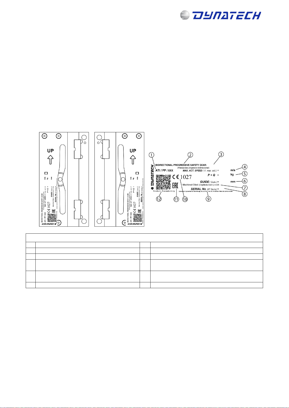
2.1IDENTIFICATION..................................................................................................................................................3
2.2SAFETYGEAR’SFEATURESANDUSE....................................................................................................................3
2.3RANGEOFUSE....................................................................................................................................................3
3INSTALLATIONANDADJUSTMENT....................................................................................................................4
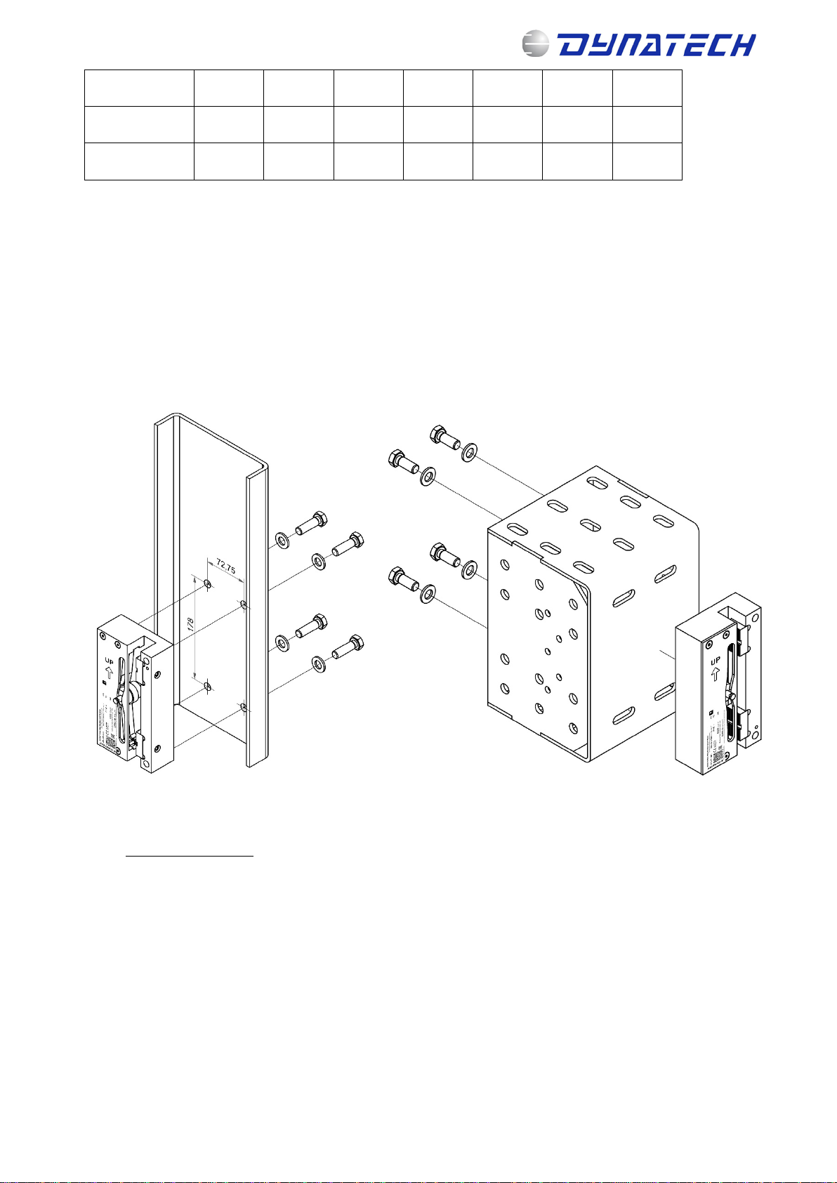
3.1ASSEMBLYONTHEFRAME..................................................................................................................................4
3.2SAFETYGEARADJUSTMENT................................................................................................................................6
3.3COUPLINGTHEDRIVINGBAR..............................................................................................................................6
3.3.1USINGDYNATECH’ST‐3DRIVINGBAR........................................................................................................6
4INSPECTIONSANDMAINTENANCE....................................................................................................................7
4.1CHECKINGTHESAFETYGEARS............................................................................................................................7
4.2PRECAUTIONS.....................................................................................................................................................8
4.3MAINTENANCE....................................................................................................................................................8
4.3.1LISTOFMAINTENANCEOPERATIONS.........................................................................................................8
4.3.2CORROSION.................................................................................................................................................8
4.4STORAGEANDSERVICELIFE................................................................................................................................8
5UCM................................................................................................................................................................9
5.1UCMSYSTEM’SPRELIMINARYDESIGN................................................................................................................9
5.2SAFETYGEARBRAKINGDISTANCECALCULATION...............................................................................................9
6GENERALDRAWING.........................................................................................................................................9
7ANNEXES........................................................................................................................................................10
_____________________________________________________

INSTRUCTIONS : PR-2000-UD Cod : DYN 07.01.10
Date : 20/10/2020 Revision : 10
3
1 GENERAL INSTRUCTIONS
Each pair of safety gears supplied is factory tared according to the required conditions of use: Total mass
(P+Q) and guide rails’ thickness. These features are indelibly displayed, along with the standardisation
password and serial number; on the protection plates on top of the safety gear boxes (see section 2.1).
It is strictly forbidden:
a) To combine and assemble safety gear boxes with different serial numbers.
b) To use a pair of safety gears for installations with characteristics different from those indicated on that
pair of safety gears’ protection plates.
c) To handle any of the safety gear’s components.
DYNATECH DYNAMICS & TECHNOLOGY, S.L. cannot be held responsible for the damage caused due to
the non-observance of any of these general instructions.
2 SAFETY GEAR IDENTIFICATION AND CHARACTERISATION
2.1 IDENTIFICATION
Figure 1: Safety gear identification
2.2 SAFETY GEAR’S FEATURES AND USE
a) The guide rails to be used should be cold drawn. Allowable tolerances for guide rail thickness should
be within the limits set by the standard: ISO 7465:2007.
b) For lubricated guide rails, the recommended lubricating oil is the type used for machines according to
ISO VG 150, although other viscosities within the margins established in ISO-VG may be accepted.
c) This safety gear can be used up to a maximum tripping speed of 2 m/s.
d) Allowable guide rail thicknesses: 5 – 16 mm.
e) Guide rail’s braking surface equal to or more than 25mm.
2.3 RANGE OF USE
Please find below the standard P+Q table. The rated values are displayed in bold in the middle row. The safety
gears, when supplied, are set to the default rated value; however, they can be used in installations with P+Q
values within the upper and lower limits.
SAFETY GEAR IDENTIFICATION LABEL
1
EU type examination certificate number
7
Guide rail type
2
Safety gear type
8
Safety gear serial number
3
Safety gear model
9
Dynatech address
4
Safety gears’maximum tripping speed (m/s)
10
Quality assurance CE marking and notified body
number
5
Total load (Kg)
11
Marking for market access tomember states of the
Customs Union
6
Guide rail thickness (mm)
12
QR product traceability code

INSTRUCTIONS : PR-2000-UD Cod : DYN 07.01.10
Date : 20/10/2020 Revision : 10
4
Lower limit 505 574 665 771 843 974 1130
P+Q (Kg) 537 621 719 834 911 1053 1222
Upper limit 577 668 773 843 979 1132 1314
Loads may be duplicated through configuration of this tandem safety gear. See ManualDYN 37/8 – Extendible
T25UD/T25 Tandem safety gear for further information.
3 INSTALLATION AND ADJUSTMENT
3.1 ASSEMBLY ON THE FRAME
The holes should be made on the frame’s uprights to secure the safety gear, according to the dimensions and
position displayed in the safety gear drawings attached (DYN 07.C002.00), ensuring that the guide rail’s axis
is centred with the frame.
To secure the safety gear onto the frame, we recommend a 79.09 Nm tightening torque for grade 8.8 M12
bolts, and of 111 Nm for grade 10.9 bolts.
Figure 2: Assembling the safety gear onto the
frame (1)
Figure 3: Assembling the safety gear onto the frame (2)
Safety gear position:
a) The safety gears should be assembled in the position displayed in Figure 4
b) A circle on one of the safety gear’s ends will indicate its upper part. This mark should always be on
the upper part during the assembly.
c) There should be an additional mark on the protection plate including the word “UP” and an arrow
indicating the safety gears’ upright position.

INSTRUCTIONS : PR-2000-UD Cod : DYN 07.01.10
Date : 20/10/2020 Revision : 10
5
Figure 4: Direction of assembly
Figure 5: Safety gear position
Figure 6: Safety gear position on inverted guide
rails
During assembly, the safety gear should be perfectly aligned with the guide rails, both vertically and
horizontally. Improper assembly may cause the safety gear to function incorrectly.

INSTRUCTIONS : PR-2000-UD Cod : DYN 07.01.10
Date : 20/10/2020 Revision : 10
6
Figure 7: Improper assembly
3.2 SAFETY GEAR ADJUSTMENT
The guide rail's position in the block should be adjusted as follows: The side of the guide rail 2 mm from the
brake shoe; the head of the guide rail 3 mm from the back of the groove (see drawing DYN 07.C002.00).
In order to avoid problems with the installation’s
normal operation, it is very important that the person
carrying out the installation rigorously observes the
distances mentioned in this item.
Please make sure that the safety gear is placed
so that the circle on the safety gear, the word “UP”
and the arrow on the protection plate are on the
upper part, as displayed in section 3.1.
Figure 8 Safety gear adjustment in relation to the
guide rail
3.3 COUPLING THE DRIVING BAR
It is the responsibility of the person who installs the safety gear to properly position the driving bar in relation
to the safety gear, as well as to properly synchronise the safety gears controlled by that driving bar. The driving
bar is properly positioned when the roller’s pivot is in the protection plate’s central position.
Once it has been fitted, and the safety gear’s rollers have been attached to the driving bar’s tripping bars, it
should be checked that both rollers operate simultaneously, controlled by the driving bar. This should be
checked in both directions, ascending and descending.
The minimum force to be generated by the overspeed governor is double the force that ensures that the
performance of the safety gears is synchronised.
The Standard demands that the installation incorporate an AC-15 or DC-13 safety contact as defined
in EN 60947-5-1.
3.3.1 USING DYNATECH’S T-3 DRIVING BAR
Both safety gears may be synchronised by assembling Dynatech’s T-3 driving bar. For more information
concerning T-3 driving bar assembly, please consult its manual: DYN08 – Instructions T-3.
It is not recommended to exceed a maximum force of 1900 N is not recommended with the governor.

INSTRUCTIONS : PR-2000-UD Cod : DYN 07.01.10
Date : 20/10/2020 Revision : 10
7
Figure 9: Safety gear synchronisation using the T-3 driving bar
4 INSPECTIONS AND MAINTENANCE
4.1 CHECKING THE SAFETY GEARS
For the safety gears to function correctly, their proper assembly and adjustment must be verified as well as
the sturdiness of the unit’s connection to the car and the guide rails, as is stated in the standard EN 81:20 and
EN 81:50.
It is recommended to follow the standard’s provisions for inspections and tests, both for commissioning and
regular testing.
The safety gear model’s behaviour curves may be requested from Dynatech based on its (P+Q) and the
installation’s rated load when tested dynamically with suspensions included.
The proper synchronisation of the safety gears may be checked by
verifying that the roller’s track is marked on both guide rails and that
they have a similar length, with the difference between the two sections
not being more than 4 cm.
The requirements for regular tests should not be greater than those for
commissioning. It is therefore recommended to always use the same
load (P/Q) and speed conditions. For better control, the maintenance
worker should have a safety gear operation record, where he or she
records the serial number and number of operations. A visual
inspection is sufficient to check that the installation has not been
damaged, see section 4.3.1.
It is not necessary to work on the safety gears due to their regular tests,
as long as their braking distance does not exceed double the distance
recorded from the first commissioning test.
After operating the safety gear in free fall, it is recommended to contact
Dynatech, or your nearest supplier, directly, who will indicate how to
proceed.
Figure 10: Braking track on guide
rail

INSTRUCTIONS : PR-2000-UD Cod : DYN 07.01.10
Date : 20/10/2020 Revision : 10
8
4.2 PRECAUTIONS
It is recommended to keep in mind the following items:
•The factory protective covering should be removed from the guide rails. In addition, it should be
checked that there are no other objects, such as screws, brackets, etc. that may interfere with the
safety gear or its driving bar.
•It should be visually checked that the safety gears are in working order, that they are not dirty or greasy
inside.
•After any inspection or test where the safety gears were tripped, it should be checked that the safety
gears have not been damaged.
•It is recommended to perform the tests near the car door to unload the car in order to facilitate
unjamming the safety gears.
•The authorised personnel should always take the necessary precautions when tripping any of the
previously installed safety gears.
4.3 MAINTENANCE
Both for maintenance and inspection, the following maintenance operations should be performed after tripping
the safety gears.
4.3.1 LIST OF MAINTENANCE OPERATIONS.
Safety gears:
•Check that there is no interference between the shoe and the guide rail, nor between the rollers and
the guide rail.
•Check the brackets and the clearance between the safety gears and the frame, readjust itif necessary.
•Clean any remaining grease, shavings or dust inside the safety gear’s housing.
•Check that there is no external element inside the safety gear’s housing.
•Check that the rollers spin freely and are not damaged or worn.
•Check that the connection between the rollers and the driving bar has not been damaged and spins
freely without being blocked.
•Visually check that the safety gears are not damaged in general.
•Check that the driving bar is in good condition and that the safety gears are correctly synchronised.
•Check that the car’s floor does not have more than a 5% slope in comparison with its normal position.
•Check that the governor’s attachment moves correctly and is in good condition.
•Check that the safety electrical contact has been correctly assembled and is functioning properly.
Guide rails:
•Clean and remove any type of dirt or dust from the guide rails.
•Eliminate the marks or burrs caused by tripping the safety gears.
•Apply a thin and even layer of lubricating oil, as indicated in item 2.2, section b) of this manual, on the
guide rails.
The list of provisions that Dynatech establishes for the maintenance of its installed equipment is added
to the Annexes.
4.3.2 CORROSION.
All DYNATECH safety gears have anti-corrosion protection. However, it should be regularly checked that the
safety gear’s mobile elements are in perfect working condition; a jamming test will not be required, just a simple
verification that all the parts are moving freely, as well as a visual inspection of the general condition of the
surfaces.
These verifications should be done more regularly, as the maintenance worker considers necessary, when the
installation is in an especially corrosive environment.
4.4 STORAGE AND SERVICE LIFE
The safety gear should be stored in a cool, dry place. It should be protected from excessive lighting. It should
never be exposed to severe weather conditions.
Storage temperature: 5 - 40ºC

INSTRUCTIONS : PR-2000-UD Cod : DYN 07.01.10
Date : 20/10/2020 Revision : 10
9
Storage humidity: 15 - 85% without condensation.
The safety gears’ packaging should be clean and dry, so that they can be clearly identified.
It is not permitted to place constant or unbalanced loads on a package, which may cause the package to be
bent, or to allow products to be stacked one on top of the other. When stacking products or packages, the
storage height should take into account their load and stability.
If the criteria established for proper maintenance are observed, the safety gears may have the same service
life as the rest of the installation’s fixed elements provided that their proper functioning is ensured and
controlled. The element’s service life is not affected by grease, dust or dirt due to the shaft’s condition or to
environmental conditions differing from those stated in this manual.
5 UCM
5.1 UCM SYSTEM’S PRELIMINARY DESIGN.
According to EN 81:20 and EN 81:50, lifts should be equipped with means for stopping uncontrolled car
movement (UCM). These means should detect UCM and stop the car. This stop must occur at a maximum
distance below 1 m (among other requirements).
The safety gears may be used as a braking device for stopping the uncontrolled movement.
The values for the safety gear’s braking distance may be calculated beforehand, but several installation
parameters must be taken into account. The more information that is known about the physical elements that
make up the system, the closer the theoretical value will be to the actual value.
These are theoretical values and may only be used in the system’s preliminary design. The installation’s
compliance with the standard requirements is pending.
5.2 SAFETY GEAR BRAKING DISTANCE CALCULATION
The detailed calculations can be found in the manual: DYN 62.04 – UCM. Braking distance.
6 GENERAL DRAWING

1
1
2
2
3
3
4
4
5
5
6
6
A A
B B
C C
D D
MEDIDAS SIN TOLERANCIA SEGÚN DIN-7168 GM PLANO COD. Nº:
Conjunto/ Assembly/ Ensemble/
Baugruppe_G16
Escala:
PR-2000-UD
CONJUNTO:
Sustituye a: Sustituido por:
DYN 07.C002.01
OBSERVACIONES:
Material:
Peso terminado:
Tto. tco:
Tto. sup:
Fichero:
Fecha Nombre
Dibujado
Norma
13/07/2015 DYNATECH
CANTIDAD POR CONJUNTO:
30,6
45
e
105
*d (mm) f (mm) e (mm) h (mm)
521 65,4 22,25 29,6
621,5 65,9 22,25 29,1
722 66,4 22,25 28,6
822,5 66,9 22,25 28,1
923
67,4 22,25 27,6
10 23,5 67,9 22,25 27,1
11 24 68,4 24,25 28,6
12 24,5 68,9 24,25 28,1
13 25 69,4 24,25 27,6
14 25,5 69,9 24,25 27,1
15 26 70,4 24,25 26,6
15,88 26,44 70,84 24,25 26,16
16 26,5 70,9 24,25 26,1
178
200
* Anchura de guía/
Guide rail thickness/
Épaisseur de guide/
Führungsschienen
56,4
30,5
d
f h
1,5 0,53,5 0,5
Historial de revisiones
Rev. Descripción Fecha Aprobado
1Se añaden tolerancias a las cotas de las guias 17/11/2017 J. Suelves

INSTRUCTIONS : PR-2000-UD Cod : DYN 07.01.10
Date : 20/10/2020 Revision : 10
10
7 ANNEXES

DATE 15/10/2020
REV 0
Maintenance company Date:
Model / Serial No.
Reference of installation
1 PUTTING INTO SERVICE FREQUENCY OK NO OK DYNATECH
INSTRUCTIONS OBSERVATIONS
1.1 Check the proper assembly of the car safety gear
First time before
putting into service
6.3.4 of EN 81:20
1.1.1 Visual check of general conditions
(1)
1.1.2 Check of the guide rail state 4.2
1.1.3 Length of marks on the guide rail 4.1
1.2 Check the proper assembly of the counterweight safety gear
First time before
putting into service
6.3.5 of EN 81:20
1.2.1 Visual check of general conditions
(1)
1.2.2 Check of the guide rail state 4.2
1.2.3 Length of marks on the guide rail 4.1
(1)
Check for wear or damage in the safety gear
2 MAINTENANCE FREQUENCY OK NO OK DYNATECH
INSTRUCTIONS OBSERVATIONS
2.1 Visual inspection and visual check 6 month 4.2
2.2 Clean, absence of strange elements 6 month 4.2
2.3 Controlled engagement of car 12 months 4.2 6.3.4 of EN 81:20
2.4 Visual inspections of wears 12 months 4.1
3OK NO OK DYNATECH
INSTRUCTIONS OBSERVATIONS
3.1 4.3.1 adjust only if required
3.2 4.3.1 adjust only if required
3.3 4.3.1 adjust only if required
3.4 4.3.1
3.5 4.3.1
3.6 4.3.1
3.7 4.3.1
3.8 4.3.1
3.9 4.3.1
3.10 4.3.1
3.11 4.3.1
3.12 4.3.1
3.13 4.3.1 only if required
3.14 4.1 have a register list
3.15 4.1
3.16
Visual check governor linkage
1. GENERAL PROVISIONS APPLICABLE TO DYNATECH SAFETY GEAR
MAINTENANCE CHECKLIST
Check that there is no interference between shoe and guide rail.
Check that there is no interference between rollers and guide rail
Check the fixings and clearance between safety gear and frame
Clean grease, chips or dust inside safety gear.
Check rollers movement
Apply lubricant on the guide rail
Length of marks on the guide rail
Visual check for wear
Begining of marks on the guide rail
Visual check for damage and defects
Check driving bar state
Check car inclination
Check safety switch
Clean guide rail
Remove marks and chips from the guide rail
Table of contents
Other Dynatech Industrial Equipment manuals
Popular Industrial Equipment manuals by other brands

Rexnord
Rexnord Falk GL32 Installation & maintenance

Crystal Clean
Crystal Clean 2725 operating manual

Phoenix Mecano
Phoenix Mecano PMZ10ES Assembly instructions

PCB Piezotronics
PCB Piezotronics 080A187 Installation and operating manual

Nibe
Nibe ERS 10-400 Installer manual

Dynaset
Dynaset HEU 320-40E manual