BLACKHAWK! STL3500 User manual

INSSTL3500GB
REV: 06.06.17
3T5 SCISSOR LIFT
STL3500
INSTRUCTION MANUAL
(Original instructions)

STL3500
2
Index
No Page
I)
WARNINGS –SAFETY INSTRUCTIONS
3-6
II)
INTRODUCTION
7
III)
PACKING, TRANSPORT AND STORAGE
7-8
IV)
GENERAL DESCRIPTION
8-9
V)
TECHNICAL SPECIFICATIONS
10-12
VI)
INSTALLATION
13-17
VII)
OPERATION
18
VIII)
MAINTENANCE
19
IX)
TROUBLESHOOTING
20
X)
XI)
SPARE PARTS
FOUNDATION DIAGRAM
21-27
28
XII)
EC DECLARATION OF CONFORMITY
29
XIII)
INITIAL TEST
30-31

STL3500
3
I) WARNINGS –SAFETY INSTRUCTIONS
The manufacturer hereby refuses to accept any responsibility for injury to persons or damage to equipment or property if
it appears that incorrect handling of the lift has occurred. This instructions manual only describes the operating and
safety aspects which are necessary to the people who are using and installing the equipment.
In order to understand the terminology used in this manual, the person performing the installation work should have
specific experience in industrial work, service, maintenance and repair activities, and must also be able to explain the
drawings and the descriptions contained in this manual to other people. At the same time, he must be aware of the
general and specific safety regulations which apply in the country where the lift is being installed.
SECURITY
It is important to read this section carefully since it contains important information about the risks which the operator of
the lift will be exposed to if the lift is not used properly. Please find below useful information about how to avoid
dangerous situations.
WARNING
In short, the lift is not suitable for the following purposes:
-Washing and spraying work
-To apply force
-To be used as a goods lift
The manufacturer hereby refuses to take into account any claim for damages arising in connection with injury to people
or damage to vehicle or other property due to incorrect and/or unauthorized use of the lift.
During lifting and lowering movements, the operator must be within the “OPERATOR AREA” as shown in figure 1. The
presence of any person in the “DANGER AREA” is strictly forbidden. The presence of people under the vehicle is only
permitted if the vehicle is in high lifting position and with mechanical safety.
Figure 1
WARNING
The lift is designed to lift cars of weight not exceeding 3500kg and hold them in a certain position in a covered
working place.
Any other form of use is forbidden.

STL3500
4
USE THE LIFT ONLY IF ALL THE SAFETY DEVICES ARE WORKING PROPERLY. IF THESE RULES ARE NOT
FOLLOWED, SERIOUS INJURY COULD BE CAUSED TO PEOPLE AS WELL AS IRREPARABLE DAMAGE TO THE
LIFT AND THE VEHICLE ON THE LIFT.
GENERAL PRECAUTIONS:
-The operator is bound to follow the regulations which apply in the country in which this lift is installed.
In addition, the operator must:
-Always work in the “OPERATOR AREA” as designated in the manual.
-Never remove the protective guards or dismantle or shut down the mechanical, electrical or other types of
safety arrangements.
-Read the safety regulations related to the lift and read the safety information provided in this manual.
The following terms have been used in this manual to describe the various types of risk:
DANGER: there is a direct possibility of danger which could lead to serious injury or death.
WARNING: indicates situations and/or actions which are unsafe and could lead to injuries of various types
except death.
CAUTION: indicates situations and/or actions, which are unsafe and could lead to light injuries to persons and/or
damage to the lift, the vehicle and other properties.
RISK OF DAMAGE DUE TO ELECTRICITY: special safety arrangements have been made on the lift
in places where the risks are very high.
RISK AND PROTECTIVE MEDIA: the risk to which the operator is exposed when the vehicle is in a raised
position, together with the protective media which have been installed, in order to limit the possible dangers.
WARNING
Non suitable lighting may be risky. Ensure that all areas next to the lift are well lit in a uniform manner.
The vehicle must be placed on the lift in such a way that there is a uniform distribution of weight over the platforms.
To ensure the safety of persons and equipment, you must make sure that:
-The “DANGER AREA” is kept under observation during the lifting process
Climbing on the platform when lifting the vehicle or when it has already been raised is strictly forbidden.
Do not move the vehicle when it is on the platform. The lift system can be removed when the lift is in the lowest
position and if it is not loaded.

STL3500
5
SAFETY DEVICES
The following safety devices have been installed to prevent overloading and damage.
-A hydraulic protection (parachute valve) prevents descending in case of hose fracture.
-Thermal protection switches the power off in case of overloading.
-Overpressure relief valve offers protection against damage due to excessive lifting.
-A foot safety device that automatically stops the lowering at approx.20cm from the floor.
-The lift is fitted with a dead-man control device. Releasing push button controls situated on the console
immediately stops lowering and lifting operations.
-A mechanical locking of the lifting arms rotation.
-A mechanical safety device.
RISKS TO PEOPLE
This paragraph describes the risks to which the operator or any other person near the working area where the lift is in
operation are exposed, if the lift is not used in the appropriate manner.
Never rest any fittings or other objects against the platform and never place such objects under the platform when there
is a load on it, since this can impede the lowering operations and may cause the vehicle to fall off the platform. (Figure 2)
Figure 2
RISK OF USE / MAINTENANCE
BLACKHAWK® uses material of the highest quality in its lifts. These must be used according to the standard specified,
and maintenance must be carried out regularly.
RISKS INVOLVED IN POSITIONING A VEHICLE
This type of risk may arise if the vehicle is not properly placed on the rubber supports (figure 3), or if the platforms are
not properly aligned with respect to the vehicle. One can avoid this by always lifting the vehicle using the car-jack
support points as advised by the vehicle manufacturer, and placing the vehicle as far as possible in the centre of the
platform.
CAUTION
Figure 3
While dismantling heavy parts (for example the motor or shafts), please note that the weight distribution ratios
change.

STL3500
6
RISK FOR THE OPERATOR (Figure 4)
This risk arises in cases when the operator is not standing at the
right place by the pump. When the lift with the vehicle is being
lowered, the operator MUST NOT stand below the descending
system. It is imperative that the operator MUST be standing in
the “OPERATER AREA” during the lifting and lowering
operations.
Figure 4
RISK OF ELECTROCUTION
Never spray water or steam of solvents or paint in the area
immediately surrounding the platform and the pump. (Figure 5)
Figure 5
RISK OF SLIPPING
This risk can be overcome by avoiding the spillage of oil or grease
in the area surrounding the lift. Apart from that, any oil spillage
which may occur should be thoroughly removed from the spot.
(Figure 6)
Figure 6
CAUTION
Never enter the vehicle or start the motor when the vehicle
is on the lift. (Figure 7)
Figure 7
CAUTION
In case of malfunction, stop the lift and block the main switch in the position “0” with a lock.
Only skilled technicians should be allowed to restart the lift.
Make sure the main power supply has been switched off before repairing and servicing the lift.

STL3500
7
II) INTRODUCTION
CAUTION
This instruction manual has been prepared for professional workshop personnel used to working with lifts, as well as for
the technicians who are in charge of the lift’s installation and maintenance.
This manual is an important part of the lift and must be kept where it is easily accessible for consultation and we
recommend particular attention in reading the chapter on safety.
All operations of the lift must be carried out by skilled and authorised personnel, especially operations of transportation,
assembly, installation, maintenance, overhaul, moving, dismantling, etc… The manufacturer cannot be held responsible
for damages to persons, vehicles or objects caused by improper use of the lift.
The lift model STL3500 has been designed and built according to:
-European Directives 2006/42/CE
-European Standard EN1493-2010
III) PACKING, TRANSPORT AND STORAGE
CAUTION
Any action involving the operation, transportation or unpacking of the equipment must ONLY be performed by trained
personnel with a proper knowledge of the lift and of the contents of this operating manual.
LIFTING AND MOVING THE PACKING
The lift is delivered assembled and packaged as follows:
N° 1 platform complete with base, scissors, positioned on 2 wooden blocks, wrapped in pluriball plastic and closed with
metal clips and relative seals.
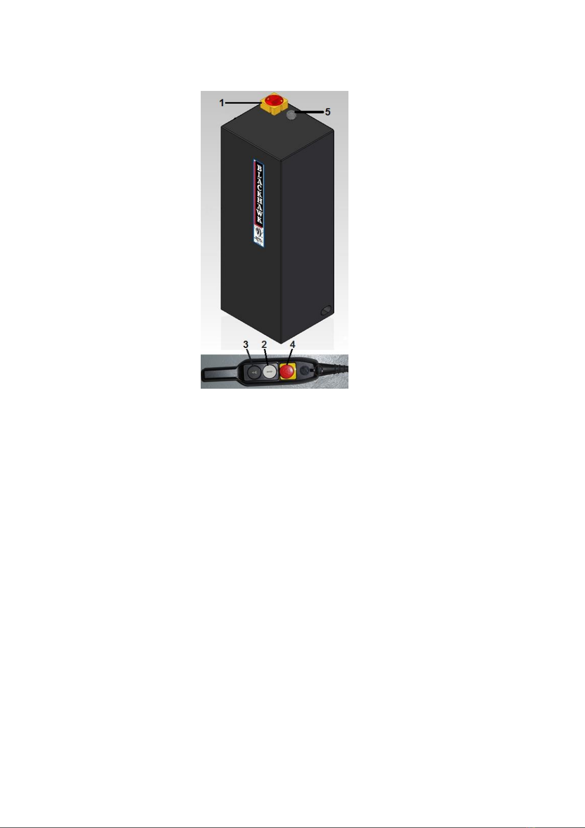
N° 1 carton containing the control unit wrapped in plastic sheet and the kit of hoses/cables for the electrical, hydraulic
and pneumatic connection.
N° 1 carton with lifting system.
DIMENSIONS
MODEL
Length
Width
Height
Weight (Kg)
LIFT WITH PACKAGING
2200
700
310
506
PUMP WITH PACKAGING
860
370
370
37
The packed lift must be lifted and moved with the help of a fork lift or a crane of adequate capacity.
STORAGE
The packed lift must always be placed in a covered area at a temperature between -10°C and +40°C and must not be
exposed to direct sunlight.
PACKING
Make sure the equipment has not been damaged during transport, and that all the components mentioned in the packing
list are physically present.
Any damage and / or missing parts must be immediately reported to the deliverer and subsequently reported and
documented to the manufacturer.

STL3500
8
2 - Scissors –Platform
TRANSPORT
The packages described on page 7 can be lifted and transported using forklifts, cranes or other lifting systems of
adequate capacity. Upon receiving goods, verify that no damage has been caused and that there are all parts indicated
on the checklist.
WARNING
PACKING REMOVAL
The wooden blocks and plastic packaging can be recycled. Total elimination of the packing has to be done in
compliance with the laws of the country where the lift is installed.
IV) GENERAL DESCRIPTION
The electric hydraulic lift is placed in a pit. It has been designed and manufactured for lifting cars and holding them in
elevated position. The main parts of the lift are:
Base:
This is the fixed part of the lift equipped with floor-fixing holes.
Scissors –Platform:
This is the mobile and lifting part of the lift. It is made up of
a series of internal and external arms joined by a eccentric.
The arms and platforms are fixed together by
rotating pins. The mobile parts move on sliding blocks.
Control unit:
The unit is made up of a metallic box that contains all
electrical, hydraulic and pneumatic functioning parts of the
lift. The 'dead man' type controls are located on the remote
control.
Figure 8
It is strongly recommended to carefully read the safety instructions first.
1 - Base

STL3500
9
MAIN CONTROL PANEL PMPLIFT
Figure 9
1.MAIN SWITCH
2.LIFTING PUSH BUTTON
3.LOWERING PUSH BUTTON
4.EMERGENCY PUSH BUTTON
5.POWER LED
1. Main switch: The switch can be padlocked to prevent the use of the lift during the maintenance.
2. Lifting push button: When pressed, motor and lifting mechanism are operated.
3. Lowering push button: When pressed, lowering mechanism is operated.
4. Emergency push button: When pressed, deactivates all controls.
5. Power led: It indicates the unit powered up.

STL3500
10
V) TECHNICAL SPECIFICATIONS
Lifting capacity: 3500 kg
Lift weight: 500 kg
Noise level: 85 dB(A) max at 1m (with the safety device) LIFTING
76.5 dB(A) average at 1m LIFTING
74 dB(A) max for the buzzer LOWERING
Operating temperature: -10°C / +40°C
Operating environment: covered
Lifting time: 50 sec
Lowering time: 1 mn 50 sec
Dimensions:
Min height –in the ground: 200 mm
Max height - Lift: 1430 mm
Max height –with lifting pads 1430 mm + 80mm = 1510mm
Chassis width: 680 mm
Chassis length: 2170 mm
PMPLIFT
Electric motor
Power
1.8kW
Voltage
230 / 400V, 3 ph. +/-10%
At a Frequency of 50Hz
230V / 10.5A
400V / 6.1A
Speed : 1400 min -1
At a Frequency of 60Hz
230V / 9A
400V / 5.2A
Speed : 1690 min -1
Number of wires
3 + earth
Max oil pressure
300 bars
Tank capacity
7 Litres
Oil type
Hydraulic ; Viscosity ISO VG32
Lifting jack strength
48 kN
Air supply pressure
7.5 à 14 bars
Arm self-locking system: YES with ball
Electro-hydraulic equipment
Rack-type mechanical safety device
Hydraulic safety device using a parachute valve
Overload relief valve
Acoustic signal for final lowering phase
Limit switch
Low voltage controls (24V)
The STL3500 has been designed and built for lifting cars of weight not exceeding 3500kg and in closed areas. It must
not be used for any other purpose, in particular:
-washing
-hoisting
-lifting people
-pressing

STL3500
11
CE APPROVAL:
The approval number assigned to this product is 75.16.130.07 dated May 2017.
MANUFACTURER: BLACKHAWK SAS RUE DU RHEINFELD 67100 STRASBOURG FRANCE
IDENTIFICATION AND CE LABEL PLATE:
Figure 10
The information given on the identification plate is necessary for any assistance or spare parts required.
OVERALL DIMENSIONS (Figure 11)

STL3500
12
THE WEIGHT OF THE VEHICLE
The lift can be used with nearly any vehicle provided that the maximum loading capacity (3500kg) is not exceeded.
Check the weight of the vehicles that are loaded.
The “DANGER AREA” (Figure 12) is to some extent determined by the dimensions of the vehicle to be lifted.
Figure 12

STL3500
13
VI) INSTALLATION
The lift must be installed taking into account the dimensions of the vehicles to be lifted, and the specified distances from
the walls, columns, other machinery, etc. The room must be at least 4500mm in height. The minimum distance from the
walls must be 2000mm (see diagram page13)
FLOOR
The lift must be installed on a flat, horizontal and sufficiently sturdy floor, with a minimum strength of 250Kg/cm².
(Concrete C30 / 37 according to NF EN206 / CN)
(Concrete C35 / 45 according to NF EN206 / CN when installation is made inside a KOREK Frame)
WARNING
Only skilled and authorized technicians must install the lift.
No unauthorised person should be present during installation.
WARNING
Unpack the goods and check for possible damage before installing the lift.
WARNING
Before working inside the control unit either for connecting the electric supply or for the repair of faults, make
sure the main power supply has been disconnected to avoid any risk of electrocution.
INSTALLATION PROCEDURE
First connect the electric and hydraulic systems before connecting the pneumatic system of the lift.
1. Check for availability of power supply
First of all, ensure that the power supply is equipped by a magneto-thermic switch (380V -16A with protection fuses) with
suitable protection devices conforming to local safety regulations and that the maximum distance of the electrical
connections and the hydraulic connections from the control unit is 3 metres.
Open the front panel of the control unit in order to make the connections.
2. Positioning of the lift
Ensure that the lift is positioned exactly in the centre of the pit frame.
Position the lift using a forklift, crane or other suitable means. Eliminate the possible slight floor level differences (max
7mm) using metallic wedges (Not supplied by BLACKHAWK®).
This is necessary in order to not affect the warranty.
For installations inside a KOREK frame, please refer to the layout supplied by BLACKHAWK®.
The lift must always be level.

STL3500
14
Figure 13
3. Hydraulic connections
Open the front panel of the control unit, remove (pull) the oil tank cap and using a funnel pour in 5 litres of
index 32 viscosity hydraulic oil. (BLACKHAWK® Part Number for 5 Litres: LX22Y)
- connect the hydraulic hose.

STL3500
15
4. Electrical diagram
IG MAIN SWITCH PT MOTOR THERMAL PROTECTION
KM CONTACTOR YV ELECTROVALVE –AIR CONTROL
M MOTOR 3 PHASES SB3 LOWER LIMIT SWITCH
L1 LIGHT R RELAY
SB1 EMERGENCY STOP B BUZZER
F1 FUSE 2A YV1 ELECTROVALVE - DESCENT
TR1 TRANSFO. 3PH - 230 / 400 - 24V Q LIMIT SWITCH
SB2 UPPER LIMIT SWITCH

16
5. Electronic card diagram
IG MAIN SWITCH
M MOTOR 3 PHASES
PT MOTOR THERMAL PROTECTION
L1 LIGHT
BUZZER SOUND SIGNAL
FC LIMIT SWITCH
EVD ELECTROVALVE - DESCENT
EVA ELECTROVALVE –AIR CONTROL
SB1 EMERGENCY STOP
SB2 UPPER LIMIT SWITCH
SB3 LOWER LIMIT SWITCH
DANGER
Do not for any reason alter the adjustment of the pressure limiter. The mechanical components are not
designed to work at a higher pressure.

STL3500
17
6. Fixing of lift
-Using a concrete drill, bore 6 holes of 16mm diameter and 120mm depth in the floor.
-Use the lift frame as a template.
-Clean the holes and with the help of a hammer, insert the supplied expansive bolts in the floor.
-With a torque wrench, tighten the bolts with a torque of 50Nm.
7. First start-up
By an officer empowered. BLACKHAWK® discharge from liability in the event of non-compliance with this directive.
WARNING
Only skilled and authorised personnel should carry out the following operations
WARNING
Follow instructions carefully in order to prevent damage to lift or injury to persons
WARNING
Ensure that the operating area is clear
-After positioning the lift and connecting the electric, hydraulic and pneumatic supplies, proceed with initial
running operations.
-Move the main switch to position “1” and press the lifting button to lift the platform to its maximum height.
(See chapter VII OPERATION)
If the motor rotates but lifting operations cannot be performed, check the motor for correct direction of
rotation and if necessary change phases on the power supply line.
-Press the lifting button again until the platform is completely raised.
-Press the lowering button to bring the platform down: it will stop about 30cm from the floor.
-Press the lowering button again to bring it back to its original position.
-Air will be automatically eliminated during each lifting- lowering cycle.
8. Use suitability
WARNING
Follow the indications carefully in order to avoid damage to people or objects and to the lift.
-Before using the lift and after fixing it to the floor and checking the safety devices, proceed with the static
and dynamic load tests by an authorized body in compliance with the laws of the country where the lift is
installed.
-The periodic controls also are to be made by the user, according to periodicity and the modalities defined by the
local regulations.

STL3500
18
VII) OPERATION
Before installing or removing of the vehicle from the lift, make sure the lift is completely down.
Position the vehicle very slowly on the lift making sure that the vehicle is well centred on the platform.
LIFTING:
1) Turn the main switch (1) to the position “1”.
2) Press on the lifting button (2)to raise the lift until the 1st stop.
3) Rotate the arms, and position the lifting pads under the vehicle observing the lifting points
recommended by the manufacturer of the vehicle.
4) Press again on the lifting button (2)to continue the lifting.
LOWERING:
5) Press on lowering button (3)until the lift stops. Press again on the lowering button (3): The anti-
crushing safety device will be activated. The lift will stop a second time to prevent the arms touching
the floor.
6) Remove the lifting pads and rotate the arms to their storage position.
7) Press again on the lowering button (3) to continue the final lowering.
Figure 14
CHECKS
-Carefully monitor the lift and its load during lifting/lowering operations.
-Make sure the acoustic alarm device works correctly during the final phase of lowering.

STL3500
19
VIII) MAINTENANCE
WARNING
Only authorised personnel must carry out maintenance. During maintenance operations it is important to follow the
instructions in the chapter “safety” and ensure that all steps are taken to avoid accidental starting of lift.
Periodic maintenance:
In order to keep the lift in peak condition, it is important to carry out periodic maintenance. The manufacturer’s guarantee
does not cover failure to do so.
The lift must be cleaned at least every 30-40 days. Do not use aggressive chemical products or high pressure
washing guns for cleaning.
Lubricate the sliding blocks and relative roller slide ways periodically with grease.
Periodically check safety devices for proper working conditions.
Check high pressure hydraulic tubes once a year.
Check the oil level inside the tank every 3-4 months. Oil must be completely changed at least every 3 years.
WARNING
Used oil is a highly polluting product. Always dispose of used oil according to laws of the country where the lift
is installed
WARNING
Brake oil must be immediately removed as it is immediately corrosive for the varnish. The piston stem must be protected
from impurities that may cause damage, prematurely wear out or even break the internal gaskets of the piston.
Demolition:
Only authorised and specialised technicians should proceed with the demolition of the lift.
Follow all precautions as specified in the chapter on “Safety”. Metallic parts can be scrapped as “scrap iron”.
All other materials must be disposed of according to laws of the country where the lift is installed.
All demolition operations must be properly documented according to laws of the country where the lift is installed at the
time of demolition.

STL3500
20
IX) TROUBLESHOOTING
WARNING
It is important to follow all precautions in the chapter on “safety” when identifying and searching for faults and carrying
out subsequent repairs.
Problem
Cause
Solution
The lift does not rise when the lifting
button is pressed.
The fuse is burnt out
Replace the fuse
The lift is heavily overloaded
Reduce the load to the maximum
weight according to the specifications.
The switch is not working
Replace the switch and call dealer
Fault in the electrical system
Call dealer for service
Too little hydraulic oil
Add hydraulic oil
The suction pump is dirty
Clean the suction pump
The lift does not lift the whole way
The lift is overloaded
Maintain max. weight according to
specifications
Voltage too low
Check voltage
Too little hydraulic oil
Add hydraulic oil
Platform keeps sliding back
Leakage in hydraulic system
Call dealer for service
The hydraulic cylinder is dirty
Call dealer for service
Non return valve is leaking
Call dealer for service
Lift does not respond while pushing the
descent button
Locking device is stuck
Check air pressure
An obstacle prevents the mobile leg of
the lift from moving
Remove any object preventing the
moving of the bearings.
Thoroughly clean the surface on which
the mobile leg of the lift moves by the
means of the bearings.
Manual Lowering:
In case of power failure, faults or electrical system failure, it is possible to lower the lit manually.
WARNING
Manual (emergency) lowering must be carried out exclusively by authorised and trained personnel
For the manual lowering operate as follows:
Lift the hook of mechanical safety and position a wedge of about 3cm under them. Open the front panel of the control
unit, unscrew the cap of the lowering electro valve and push the spring piston in the inside. At this point the lift will lower.
Once this operation is finished and electrical current is restored, screw the cap of the electro valve back on and remove
the wedge under the mechanical safety device.
WARNING
Check the danger area during the operation. In case of danger, to stop the descent, release the pressure on the spring
piston of the electro valve.
Table of contents
Other BLACKHAWK! Scissor Lift manuals